Juniper ACX5048 Hardware Manual
Universal metro router
Hide thumbs
Also See for ACX5048:
- Quick start manual (13 pages) ,
- Configuration manual (3270 pages) ,
- Manual (232 pages)
Table of Contents
Advertisement
Quick Links
Advertisement
Table of Contents
Troubleshooting

Related Manuals for Juniper ACX5048


Summary of Contents for Juniper ACX5048
- Page 1 ACX5048 and ACX5096 Universal Metro Router Hardware Guide Published 2020-12-14...
- Page 2 END USER LICENSE AGREEMENT The Juniper Networks product that is the subject of this technical documentation consists of (or is intended for use with) Juniper Networks software. Use of such software is subject to the terms and conditions of the End User License Agreement (“EULA”) posted at https://support.juniper.net/support/eula/.
-
Page 3: Table Of Contents
Creating a Service Request with JTAC | xv Overview ACX5048 and ACX5096 System Overview | 17 ACX5000 Universal Metro Router Overview | 17 Benefits of the ACX5048 and ACX5096 Routers | 18 ACX5048 Router | 18 ACX5096 Router | 19 ACX5000 Router Models | 19... - Page 4 DC Power Specifications for an ACX5000 Router | 75 Site Planning, Preparation, and Specifications Site Preparation Checklist for an ACX5000 Router | 78 ACX5048 and ACX5096 Site Guidelines and Requirements | 79 General Site Guidelines | 80 Site Electrical Wiring Guidelines | 80...
- Page 5 Rack Requirements for an ACX5000 Router | 86 ACX5048 and ACX5096 Network Cable and Transceiver Planning | 88 Determining Transceiver Support for the ACX5000 | 88 Cable Specifications for QSFP+ and QSFP28 Transceivers | 89 Calculating Power Budget and Power Margin for Fiber-Optic Cables | 91...
- Page 6 Removing, Installing, and Maintaining Components Maintaining ACX5048 and ACX5096 Components | 126 Removing a Transceiver from an ACX5000 Router | 126 Installing a Transceiver in an ACX5000 Router | 128 Disconnecting a Fiber-Optic Cable from an ACX5000 Router | 130...
- Page 7 Safety and Compliance Information General Safety Guidelines and Warnings | 158 Definitions of Safety Warning Levels | 159 Qualified Personnel Warning | 162 Warning Statement for Norway and Sweden | 163 Fire Safety Requirements | 163 Fire Suppression | 163 Fire Suppression Equipment | 163 Installation Instructions Warning | 165 Chassis and Component Lifting Guidelines | 165...
- Page 8 viii Product Disposal Warning | 193 General Electrical Safety Guidelines and Warnings | 194 Action to Take After an Electrical Accident | 195 Prevention of Electrostatic Discharge Damage | 196 AC Power Electrical Safety Guidelines | 197 AC Power Disconnection Warning | 199 ACX5000 DC Power Electrical Safety Guidelines and Warnings | 199 DC Power Copper Conductors Warning | 201 DC Power Disconnection Warning | 202...
-
Page 9: About The Documentation
Use this guide to install hardware and perform initial software configuration, routine maintenance, and troubleshooting for the ACX5048 and ACX5096 Universal Metro router. After completing the installation and basic configuration procedures covered in this guide, refer to the Junos OS documentation for information about further software configuration. -
Page 10: Merging A Full Example
If the example configuration contains the top level of the hierarchy (or multiple hierarchies), the example is a full example. In this case, use the load merge command. If the example configuration does not start at the top level of the hierarchy, the example is a snippet. In this case, use the load merge relative command. -
Page 11: Merging A Snippet
Merging a Snippet To merge a snippet, follow these steps: 1. From the HTML or PDF version of the manual, copy a configuration snippet into a text file, save the file with a name, and copy the file to a directory on your routing platform. For example, copy the following snippet to a file and name the file ex-script-snippet.conf. - Page 12 Table 1: Notice Icons Icon Meaning Description Informational note Indicates important features or instructions. Caution Indicates a situation that might result in loss of data or hardware damage. Warning Alerts you to the risk of personal injury or death. Laser warning Alerts you to the risk of personal injury from a laser.
- Page 13 xiii Table 2: Text and Syntax Conventions (continued) Convention Description Examples Italic text like this Represents variables (options for Configure the machine’s domain which you substitute a value) in name: commands or configuration [edit] statements. root@# set system domain-name domain-name Text like this Represents names of configuration To configure a stub area, include...
-
Page 14: Documentation Feedback
URL or page number, and software version (if applicable). Requesting Technical Support Technical product support is available through the Juniper Networks Technical Assistance Center (JTAC). If you are a customer with an active Juniper Care or Partner Support Services support contract, or are... -
Page 15: Self-Help Online Tools And Resources
JTAC hours of operation—The JTAC centers have resources available 24 hours a day, 7 days a week, 365 days a year. Self-Help Online Tools and Resources For quick and easy problem resolution, Juniper Networks has designed an online self-service portal called the Customer Support Center (CSC) that provides you with the following features: Find CSC offerings: https://www.juniper.net/customers/support/... -
Page 16: Overview
C HAPTER Overview ACX5048 and ACX5096 System Overview | 17 ACX5048 and ACX5096 Chassis | 47 ACX5048 and ACX5096 Cooling System | 60 ACX5048 and ACX5096 Power System | 65... -
Page 17: Acx5048 And Acx5096 System Overview
The ACX5000 router portfolio consists of high-performance fixed-configuration routers that add higher port densities, additional scalability, and improved latency to the ACX Series. The ACX5000 routers are available in two models—ACX5048 and ACX5096. See “ACX5000 Router Models”... -
Page 18: Benefits Of The Acx5048 And Acx5096 Routers
Junos OS is installed on an ACX5000 router’s 32-gigabyte (GB) internal solid state flash drive. The same Junos OS code base that runs on an ACX5000 routers also runs on all Juniper Networks QFX and EX Series switches, and J Series, M Series, MX Series, ACX Series and T Series routers. -
Page 19: Acx5096 Router
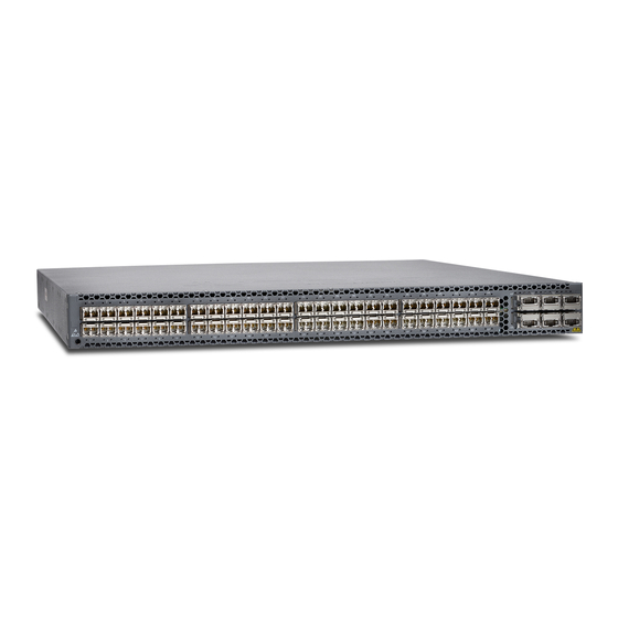
ACX5096 Router As shown in Figure 2 on page 19, the ACX5096 is a is a 10-Gigabit Ethernet enhanced small form-factor pluggable (SFP+) top-of-rack router with 96 SFP+ ports and 8 quad SFP+ (QSFP+) ports. Each SFP+ port can operate as a native 10-Gbps port or as a 1-Gbps port. The QSFP+ ports 96 and 100 can operate at native 40 Gbps speed or can be channelized to 4 independent 10 Gbps port speeds. -
Page 20: Field-Replaceable Units In An Acx5000 Router
Table 3: ACX5000 Router Model Numbers and Description Number Power M a n a g e m e n t Model Number Ports Supply Ports Airflow ACX5048-AC 48 SFP+ and 6 QSFP+ Air Out transceivers (front-to-back) ACX5048-DC 48 SFP+ and 6 QSFP+ Air Out transceivers... - Page 21 Do not operate the router with missing FRUs for longer than one minute. NOTE: If you have a Juniper J-Care service contract, register any addition, change, or upgrade of hardware components at https://www.juniper.net/customers/csc/management/updateinstallbase.jsp .
-
Page 22: Understanding Hardware Redundancy Of An Acx5000 Router Components And Functionality
Do not connect feed A and feed B to the same power supply input terminal. Cooling system—The 1 U ACX5048 router has five fan modules; the 2 U ACX5096 router has three fan modules. If a fan module fails and is unable to keep the ACX5000 router within the desired temperature thresholds, chassis alarms occur and the ACX5000 router can shut down. -
Page 23: Acx5048 Router Hardware And Cli Terminology Mapping
Junos OS command line interface (CLI). Figure 3 on page 24 shows the port locations of the interfaces. Table 5: CLI Equivalents of Terms Used in Documentation for an ACX5048 Router Hardware Item (as Description (as... -
Page 24: Acx5096 Router Hardware And Cli Terminology Mapping
Table 5: CLI Equivalents of Terms Used in Documentation for an ACX5048 Router (continued) Hardware Item (as Description (as Value (as displayed displayed in the displayed in the Item in in the CLI) CLI) CLI) Documentation Additional Information n is a value in the “Cooling System and Airflow... - Page 25 Table 6: CLI Equivalents of Terms Used in Documentation for an ACX5096 Router (continued) Hardware Item (as Description (as Value (as displayed displayed in the displayed in the Item in in the CLI) CLI) CLI) Documentation Additional Information PIC (n) Abbreviated name Value of n is always The router does not...
-
Page 26: Protocols And Applications Supported By Acx Series Routers
MTU values are not limited to 1500 but can range between 256 to 9216. For more information, see the Knowledge Base (KB) article KB28179 at: https://kb.juniper.net/InfoCenter/index?page=content&id=KB28179. Table 7: Protocols and Applications Supported by ACX Series Routers Protocol or... - Page 27 Table 7: Protocols and Applications Supported by ACX Series Routers (continued) Protocol or Application A C X 1 0 0 0 A C X 1 1 0 0 A C X 2 0 0 0 A C X 2 1 0 0 A C X 2 2 0 0 A C X 4 0 0 0 A C X 5 0 4 8...
- Page 28 Table 7: Protocols and Applications Supported by ACX Series Routers (continued) Protocol or Application A C X 1 0 0 0 A C X 1 1 0 0 A C X 2 0 0 0 A C X 2 1 0 0 A C X 2 2 0 0 A C X 4 0 0 0 A C X 5 0 4 8...
- Page 29 Table 7: Protocols and Applications Supported by ACX Series Routers (continued) Protocol or Application A C X 1 0 0 0 A C X 1 1 0 0 A C X 2 0 0 0 A C X 2 1 0 0 A C X 2 2 0 0 A C X 4 0 0 0 A C X 5 0 4 8...
- Page 30 Table 7: Protocols and Applications Supported by ACX Series Routers (continued) Protocol or Application A C X 1 0 0 0 A C X 1 1 0 0 A C X 2 0 0 0 A C X 2 1 0 0 A C X 2 2 0 0 A C X 4 0 0 0 A C X 5 0 4 8...
- Page 31 Table 7: Protocols and Applications Supported by ACX Series Routers (continued) Protocol or Application A C X 1 0 0 0 A C X 1 1 0 0 A C X 2 0 0 0 A C X 2 1 0 0 A C X 2 2 0 0 A C X 4 0 0 0 A C X 5 0 4 8...
- Page 32 Table 7: Protocols and Applications Supported by ACX Series Routers (continued) Protocol or Application A C X 1 0 0 0 A C X 1 1 0 0 A C X 2 0 0 0 A C X 2 1 0 0 A C X 2 2 0 0 A C X 4 0 0 0 A C X 5 0 4 8...
- Page 33 Table 7: Protocols and Applications Supported by ACX Series Routers (continued) Protocol or Application A C X 1 0 0 0 A C X 1 1 0 0 A C X 2 0 0 0 A C X 2 1 0 0 A C X 2 2 0 0 A C X 4 0 0 0 A C X 5 0 4 8...
- Page 34 Table 7: Protocols and Applications Supported by ACX Series Routers (continued) Protocol or Application A C X 1 0 0 0 A C X 1 1 0 0 A C X 2 0 0 0 A C X 2 1 0 0 A C X 2 2 0 0 A C X 4 0 0 0 A C X 5 0 4 8...
- Page 35 Table 7: Protocols and Applications Supported by ACX Series Routers (continued) Protocol or Application A C X 1 0 0 0 A C X 1 1 0 0 A C X 2 0 0 0 A C X 2 1 0 0 A C X 2 2 0 0 A C X 4 0 0 0 A C X 5 0 4 8...
- Page 36 Table 7: Protocols and Applications Supported by ACX Series Routers (continued) Protocol or Application A C X 1 0 0 0 A C X 1 1 0 0 A C X 2 0 0 0 A C X 2 1 0 0 A C X 2 2 0 0 A C X 4 0 0 0 A C X 5 0 4 8...
- Page 37 Table 7: Protocols and Applications Supported by ACX Series Routers (continued) Protocol or Application A C X 1 0 0 0 A C X 1 1 0 0 A C X 2 0 0 0 A C X 2 1 0 0 A C X 2 2 0 0 A C X 4 0 0 0 A C X 5 0 4 8...
- Page 38 Table 7: Protocols and Applications Supported by ACX Series Routers (continued) Protocol or Application A C X 1 0 0 0 A C X 1 1 0 0 A C X 2 0 0 0 A C X 2 1 0 0 A C X 2 2 0 0 A C X 4 0 0 0 A C X 5 0 4 8...
- Page 39 Table 7: Protocols and Applications Supported by ACX Series Routers (continued) Protocol or Application A C X 1 0 0 0 A C X 1 1 0 0 A C X 2 0 0 0 A C X 2 1 0 0 A C X 2 2 0 0 A C X 4 0 0 0 A C X 5 0 4 8...
- Page 40 Table 7: Protocols and Applications Supported by ACX Series Routers (continued) Protocol or Application A C X 1 0 0 0 A C X 1 1 0 0 A C X 2 0 0 0 A C X 2 1 0 0 A C X 2 2 0 0 A C X 4 0 0 0 A C X 5 0 4 8...
- Page 41 Table 7: Protocols and Applications Supported by ACX Series Routers (continued) Protocol or Application A C X 1 0 0 0 A C X 1 1 0 0 A C X 2 0 0 0 A C X 2 1 0 0 A C X 2 2 0 0 A C X 4 0 0 0 A C X 5 0 4 8...
- Page 42 Table 7: Protocols and Applications Supported by ACX Series Routers (continued) Protocol or Application A C X 1 0 0 0 A C X 1 1 0 0 A C X 2 0 0 0 A C X 2 1 0 0 A C X 2 2 0 0 A C X 4 0 0 0 A C X 5 0 4 8...
- Page 43 Table 7: Protocols and Applications Supported by ACX Series Routers (continued) Protocol or Application A C X 1 0 0 0 A C X 1 1 0 0 A C X 2 0 0 0 A C X 2 1 0 0 A C X 2 2 0 0 A C X 4 0 0 0 A C X 5 0 4 8...
- Page 44 Table 7: Protocols and Applications Supported by ACX Series Routers (continued) Protocol or Application A C X 1 0 0 0 A C X 1 1 0 0 A C X 2 0 0 0 A C X 2 1 0 0 A C X 2 2 0 0 A C X 4 0 0 0 A C X 5 0 4 8...
- Page 45 Table 7: Protocols and Applications Supported by ACX Series Routers (continued) Protocol or Application A C X 1 0 0 0 A C X 1 1 0 0 A C X 2 0 0 0 A C X 2 1 0 0 A C X 2 2 0 0 A C X 4 0 0 0 A C X 5 0 4 8...
- Page 46 12. 3 X54 18.2R1 –D15 -D10 –D20 –D20 –D20 (Indoor) 12. 3 X54 –D25 ( O utdoor) Juniper Networks 12.2 12.2R2 12.2 12.2R2 12. 3 X54 12. 3 x51 15. 1 X54 15. 1 X54 12. 3 X54 18.2R1 enterprise-specific MIBs –D15...
-
Page 47: Acx5048 And Acx5096 Chassis
2 U ACX5096 router. Figure 7 on page 48 Figure 8 on page 49 for FRUs and management panel detail. Figure 5: ACX5048, FRU End 1 U Product SKU Management panel Power supply units — — Fan modules... - Page 48 Figure 6: ACX5096, FRU End 2 U Product SKU Figure 7: Management Panel Components on ACX5048 Status LEDs RJ-45 console port (CON) ) — — em1–SFP management Ethernet port (C1) USB port — — Cage (socket for either 1 GbE copper SFP or fiber SFP) em0–RJ-45 (1000 Base-T) management Ethernet...
- Page 49 Figure 8: Management Panel Components on ACX5096 Status LEDs RJ-45 console port (C0N) ) — — em1–SFP management Ethernet port (C1) USB port — — Cage (socket for either 1 GbE copper SFP or fiber SFP) em0–RJ-45 (1000 Base-T) management Ethernet —...
-
Page 50: Port Panel Of An Acx5048 Router
Port Panel of an ACX5048 Router The port panel of the ACX5048 supports up to a maximum of 72 logical 10 GbE ports when operating as a standalone router. Forty-eight physical ports(0 through 47) support 10 Gbps small form-factor pluggable plus (SFP+) transceivers. -
Page 51: Port Panel Of An Acx5096 Router
Figure 9: ACX5048 Router Port Panel Electrostatic Discharge (ESD) terminal 40 Gigabit Ethernet ports (6) — — 10 Gigabit Ethernet ports (48) — Port Panel of an ACX5096 Router IN THIS SECTION Router Ports | 52 Channelizing Interfaces | 53 The port panel of the ACX5096 router consists of 96 small form-factor pluggable plus (SFP+) and 8 quad small-form factor pluggable plus (QSFP+) ports. -
Page 52: Router Ports
Figure 10: ACX5096 Router Port Panel Electrostatic Discharge (ESD) terminal 40 Gigabit Ethernet ports (8) — — 10 Gigabit Ethernet ports (96) — This topic describes: Router Ports The ACX5096 ports, (0 through 95) support: 1 Gbps SFP transceivers 10 Gbps SFP+ transceivers 10 Gbps direct attach copper (DAC) cables Ports 96 through 104 support: 40 Gbps QSFP+ transceivers... -
Page 53: Channelizing Interfaces
Channelizing Interfaces The port panel of an ACX5096 supports up to a maximum of 104 logical 10 GbE ports that can be distributed over 96 small form-factor pluggable plus (SFP+) and 8 quad small-form factor pluggable plus (QSFP+) transceivers . Because of an 104 port restriction, only two of the eight QSFP+ can be channelized. Depending on how you set the system mode for channelization, the behavior of channelization for the QSFP+ changes. - Page 54 Table 8 on page 54 describes the chassis status LEDs on an ACX5000 router, their colors and states, and the status they indicate. You can view the colors of the three LEDs remotely through the CLI by issuing the operational mode command show chassis lcd. Table 8: Chassis Status LEDs on an ACX5000 Router Name Color...
-
Page 55: Management Port Leds On An Acx5000 Router
Table 8: Chassis Status LEDs on an ACX5000 Router (continued) Name Color State Description ID–Identification Unlit The beacon feature is not enabled on the router. This feature is enabled using the request chassis beacon command. Blue Blinking The beacon feature is enabled on the router. - Page 56 Figure 12: Management Port LEDs on an ACX5000 Router Status LEDs RJ-45 console port (C0N) ) — — em1–SFP management Ethernet port (C1) USB port — — Cage (socket for either 10/100/1000 Base-T RJ45 SFP or 1GbE fiber SFP) em0–RJ-45 (10/100/1000 Base-T) management —...
-
Page 57: Access Port And Uplink Port Leds On An Acx5000 Router
Table 9: Management Port LEDs on an ACX5000 Router Color State Description Link/Activity Unlit No link is established, there is a fault, or the link is down. Green On steadily A link is established, but there is no link activity. Blinking or flickering A link is established, and there is link activity. - Page 58 Table 10: ACX5000 Access Port and Uplink LED Locations Model Port Type Indicators Location ACX5048 SFP+ Link Status ACX5096 SFP+ Link Status Table 11 on page 58 describes how to interpret the SFP+ port LEDs. Table 11: Network Port LEDs on SFP+ Ports on an ACX5000 Router...
- Page 59 Table 11: Network Port LEDs on SFP+ Ports on an ACX5000 Router (continued) Color State Description Status Unlit The link is down. Amber Blinking The beacon function is enabled on the port. Green Blinking A 1-Gigabit Ethernet transceiver is installed in the port and the link is established.
-
Page 60: Acx5048 And Acx5096 Cooling System
SEE ALSO Installing a Transceiver in an ACX5000 Router | 128 Connecting a Fiber-Optic Cable to an ACX5000 Router | 131 ACX5048 and ACX5096 Cooling System IN THIS SECTION Cooling System and Airflow in an ACX5000 Router | 60 Fan Module LED on an ACX5000 Router | 64... - Page 61 Figure 14 on page 61 shows the 2 U fan module. Figure 13: 1 U Fan Module Used in ACX5048 Figure 14: 2 U Fan Module Used in ACX5096 You remove and replace a fan module from the FRU end of the chassis. The router continues to operate for a limited period of time (30 seconds) during the replacement of the fan module without thermal shutdown.
- Page 62 AIR labels. In data center deployments, position the router in such a manner that the AIR OUT labels on router components are next to the hot aisle. Figure 15: Air Out Airflow Through 1 U ACX5048 Chassis...
-
Page 63: Fan Module Status
Figure 16: Air Out Airflow Through 2 U ACX5096 Chassis Fan Module Status You can check the status of fan modules through the show system alarms command or by looking at the LEDs next to each fan module. Each router has a Status LED (labeled ST) for each fan module on the left side of the corresponding fan module slot. -
Page 64: Fan Module Led On An Acx5000 Router
SEE ALSO Prevention of Electrostatic Discharge Damage | 196 Installing a Fan Module in an ACX5000 Router | 134 Removing a Fan Module from an ACX5000 Router | 133 Fan Module LED on an ACX5000 Router Figure 17 on page 64 shows the location of the LED next to the fan module. -
Page 65: Acx5048 And Acx5096 Power System
The AC power supply in 1 U ACX5048 is 650 W; the AC power supply in the 2 U ACX5096, is 850 W. Both power supplies look identical. Be sure to use the correct power supply for your chassis product SKU... - Page 66 Figure 18: 1 U AC Power Supply in an ACX5048 Handle AC appliance inlet — — Security latch Ejector lever — — Figure 19: 2 U AC Power Supply in an ACX5096 The power supply provides port-to-FRU airflow depending on the product SKU you purchase. The power supplies either have labels on the handles that indicate the direction of airflow or they have color-coded handles with a fan icon.
-
Page 67: Ac Power Supply Leds On An Acx5000 Router
Table 16: Airflow Direction in an ACX5000 AC Power Supplies ACX5000 Direction of Color of Power Product SKUs Wattage Product Number Airflow Supply Handle ACX5048 650 W JPSU-650W-AC-AFO Port-to-FRU Juniper Gold ACX5096 850 W JPSU-850W-AC-AFO SEE ALSO Connecting AC Power to an ACX5000 Router | 112... - Page 68 Figure 21: AC Power Supply LEDs on an ACX5000 Router AC OK DC OK Fault AC OK DC OK Fault Table 17 on page 68 describes the LEDs on the AC power supplies. Table 17: AC Power Supply LEDs on an ACX5000 Router Color State Description...
-
Page 69: Dc Power Supply For An Acx5000 Router
The DC power supply in 1 U ACX5048 is 650 W with dual feeds for power resiliency. The DC power supply in the 2 U ACX5096 is 850 W with dual feeds for power resiliency. Both power supplies have a similar design and look identical. - Page 70 Figure 23: DC Power Supply for an ACX5096 Terminal block Ejector lever — — ESD grounding point Handle — — NOTE: The DC power supply in the router has four terminals labeled V–, V–, V+, and V+ (see Figure 24 on page 71) for connecting DC power source cables labeled positive (+) and negative (–).
- Page 71 Table 18: Airflow Direction in ACX5000 DC Power Supplies Direction of Color of Power Router Model Wattage Product Number Airflow Supply Handle ACX5048 650 W JPSU-650W-DC-AFO Port-to-FRU Juniper Gold ACX5096 850 W JPSU-850W-DC-AFO SEE ALSO...
-
Page 72: Dc Power Supply Leds On An Acx5000 Router
DC Power Supply LEDs on an ACX5000 Router Figure 25 on page 72 shows the location of the LEDs on the DC power supply. Figure 25: DC Power Supply Faceplate on an ACX5000 Router Input LED Fault LED — — Output LED —... -
Page 73: Ac Power Specifications For An Acx5000 Router
100 / 240 VAC AC input line frequency 50–60 Hz (all product SKUs) AC input current rating 4.5 A at 100–120 VAC 2.0 A at 200–240 VAC Typical power consumption ACX5048 230 W ACX5096 315 W Maximum power consumption ACX5048 365 W... -
Page 74: Ac Power Cord Specifications For An Acx5000 Router
General Safety Guidelines and Warnings | 158 General Electrical Safety Guidelines and Warnings | 194 AC Power Cord Specifications for an ACX5000 Router Detachable AC power cords are shipped with the chassis, if you include them as part of your order. The coupler is type C13 as described by International Electrotechnical Commission (IEC) standard 60320. -
Page 75: Dc Power Specifications For An Acx5000 Router
Table 21: AC Power Cord Specifications Country/Region Electrical Specifications Plug Standards Juniper Model Number Graphic Australia 250 VAC, 10 A, 50 Hz AS/NZ 3109-1996 CBL-GP-PWR-C13-AU China 250 VAC, 10 A, 50 Hz GB 1002-1996 CBL-GP-PWR-C13-CH Europe (except Italy, 250 VAC, 10 A, 50 Hz... - Page 76 Table 22: DC Power Specifications for an ACX5000 Router Item Router Model Specifications DC input voltage ACX5048 Rated operating voltage: –48 VDC to -60 VDC Operating voltage range: –40 VDC through –72 VDC ACX5096 Rated operating voltage: VDC –48 VDC to –60 VDC Operating voltage range: –40 VDC through –72 VDC...
-
Page 77: Site Planning, Preparation, And Specifications
Site Planning, Preparation, and Specifications Site Preparation Checklist for an ACX5000 Router | 78 ACX5048 and ACX5096 Site Guidelines and Requirements | 79 ACX5048 and ACX5096 Network Cable and Transceiver Planning | 88 ACX5048 and ACX5096 Management Cable Specifications and Pinouts | 95... -
Page 78: Site Preparation Checklist For An Acx5000 Router
Site Preparation Checklist for an ACX5000 Router The checklist in Table 23 on page 78 summarizes the tasks you need to perform when preparing a site for an ACX5000 router installation. Table 23: Site Preparation Checklist Item or Task For More Information Performed By Date Environment... -
Page 79: Acx5048 And Acx5096 Site Guidelines And Requirements
Plan the cable routing and management. RELATED DOCUMENTATION General Safety Guidelines and Warnings | 158 ACX5048 and ACX5096 Site Guidelines and Requirements IN THIS SECTION General Site Guidelines | 80 Site Electrical Wiring Guidelines | 80... -
Page 80: General Site Guidelines
General Site Guidelines Efficient device operation requires proper site planning and maintenance and proper layout of the equipment, rack or cabinet (if used), and wiring closet. To plan and create an acceptable operating environment for your device and prevent environmentally caused equipment failures: Keep the area around the chassis free from dust and conductive material, such as metal flakes. -
Page 81: Clearance Requirements For Airflow And Hardware Maintenance For An Acx5000 Router
Table 24: Site Electrical Wiring Guidelines (continued) Site Wiring Factor Guidelines Radio To reduce or eliminate RFI from your site wiring, do the following: frequency Use a twisted-pair cable with a good distribution of grounding conductors. interference If you must exceed the recommended distances, use a high-quality twisted-pair cable with one ground conductor for each data signal when applicable. -
Page 82: Chassis Physical Specifications For An Acx5000 Router
With FRUs installed: 32 lbs including handles for Fans (14.5 kg) and PSUs) SEE ALSO Mounting an ACX5000 Router in a Rack or Cabinet | 103 ACX5048 and ACX5096 Installation Overview | 101 Removing an ACX5000 Router from a Rack or Cabinet | 143... -
Page 83: Acx5000 Router Environmental Specifications
ACX5000 Router Environmental Specifications The router must be installed in a rack or cabinet. It must be housed in a dry, clean, well-ventilated, and temperature-controlled environment. Follow these environmental guidelines: The site must be as dust-free as possible, because dust can clog air intake vents and filters, reducing the efficiency of the router cooling system. -
Page 84: Acx5000 Chassis Grounding Cable And Lug Specifications
SEE ALSO ACX5048 and ACX5096 Installation Overview | 101 ACX5000 Chassis Grounding Cable and Lug Specifications For installations that require a separate grounding conductor to the chassis, the router must be adequately grounded before power is connected to ensure proper operation and to meet safety and electromagnetic interference (EMI) requirements. -
Page 85: Cabinet Requirements For An Acx5000 Router
The grounding cable that you provide for a ACX5000 router must be 14 AWG (2 mm²), minimum 60° C wire, or as permitted by the local code. Cabinet Requirements for an ACX5000 Router You can mount an ACX5000 router in an enclosure or cabinet that contains a four-post 19-in. open rack as defined in Cabinets, Racks, Panels, and Associated Equipment (document number EIA-310-D) published by the Electronics Industry Association. -
Page 86: Rack Requirements For An Acx5000 Router
SEE ALSO Mounting an ACX5000 Router in a Rack or Cabinet | 103 Rack Requirements for an ACX5000 Router All ACX5000 routers are designed to be installed on four-post racks. The ACX5096 can also be installed on two-post racks. Rack requirements consist of: Rack type Mounting bracket hole spacing Rack size and strength... - Page 87 The outer edges of the front-mounting brackets extend the width to 19 in. (48.26 cm). For ACX5048 routers, space the front and rear rack rails between 23 in. (58.5 cm) and 30.25 in. (76.8 cm) front-to-back. The rack must be strong enough to support the weight of the router.
-
Page 88: Acx5048 And Acx5096 Network Cable And Transceiver Planning
These 40 GbE ports support QSFP+ transceivers, QSFP+ direct-attach copper (DAC) cables, and DAC breakout cables (DACBO). The ACX5048 has 6 QSFP+ ports; the ACX5096 has 8 QSFP+ ports that can all be used as uplinks. -
Page 89: Cable Specifications For Qsfp+ And Qsfp28 Transceivers
The 40GbE quad small form-factor pluggable plus (QSFP+) and 100GbE quad small form-factor pluggable 28 (QSFP28) transceivers that are used in ACX Series routers use 12-ribbon multimode fiber crossover cables with MPO socket connectors (SR4 optics only). The fiber can be either OM3 or OM4. Juniper Networks does not sell these cables. - Page 90 CAUTION: To maintain agency approvals, use only a properly constructed, shielded cable. TIP: Ensure that you order cables with the correct polarity. Vendors refer to these crossover cables as key up to key up, latch up to latch up, Type B, or Method B. If you are using patch panels between two QSFP+ transceivers or two QSFP28 transceivers, ensure that the proper polarity is maintained through the cable plant.
-
Page 91: Calculating Power Budget And Power Margin For Fiber-Optic Cables
You can use the Hardware Compatibility Tool to find information about the pluggable transceivers supported on your Juniper Networks device. To calculate the power budget and power margin, perform the following tasks: How to Calculate Power Budget for Fiber-Optic Cable | 92... -
Page 92: How To Calculate Power Budget For Fiber-Optic Cable
How to Calculate Power Budget for Fiber-Optic Cable To ensure that fiber-optic connections have sufficient power for correct operation, you need to calculate the link's power budget, which is the maximum amount of power it can transmit. When you calculate the power budget, you use a worst-case analysis to provide a margin of error, even though all the parts of an actual system do not operate at the worst-case levels. - Page 93 Table 31: Estimated Values for Factors Causing Link Loss (continued) Link-Loss Factor Estimated Link-Loss Value Connector 0.5 dB Splice 0.5 dB Fiber attenuation Single mode—0.5 dB/km Multimode—1 dB/km The following sample calculation for a 2-km-long multimode link with a power budget (P ) of 13 dB uses the estimated values from Table 31 on page 92...
-
Page 94: Fiber-Optic Cable Signal Loss, Attenuation, And Dispersion
Fiber-Optic Cable Signal Loss, Attenuation, and Dispersion IN THIS SECTION Signal Loss in Multimode and Single-Mode Fiber-Optic Cable | 94 Attenuation and Dispersion in Fiber-Optic Cable | 94 Signal Loss in Multimode and Single-Mode Fiber-Optic Cable Multimode fiber is large enough in diameter to allow rays of light to reflect internally (bounce off the walls of the fiber). -
Page 95: Acx5048 And Acx5096 Management Cable Specifications And Pinouts
When chromatic dispersion is at the maximum allowed, its effect can be considered as a power penalty in the power budget. The optical power budget must allow for the sum of component attenuation, power penalties (including those from dispersion), and a safety margin for unexpected losses. ACX5048 and ACX5096 Management Cable Specifications and Pinouts IN THIS SECTION... -
Page 96: Management Port Connector Pinouts For An Acx5000 Router
NOTE: The ACX5000 router management port can be configured with a small form-factor pluggable (SFP) transceivers. See the Hardware Compatibility Tool for more information: https://pathfinder.juniper.net/hct/product/#prd=ACX5000 Table 32: Cable Specifications for Console and Management Connections for the ACX5000 Router Port on... -
Page 97: Console Port Connector Pinouts For An Acx5000 Router
Table 33: RJ-45 Management Port Connector Pinouts for an ACX5000 Router (continued) Signal Description TRP2– Transmit/receive data pair 2 TRP4+ Transmit/receive data pair 4 TRP4– Transmit/receive data pair 4 SEE ALSO Management Port LEDs on an ACX5000 Router | 55 Console Port Connector Pinouts for an ACX5000 Router The console port (labeled CON, C1, or CONSOLE) is an RS-232 serial interface that uses an RJ-45 connector to connect to a console management device. -
Page 98: Usb Port Specifications For An Acx5000 Router
Connecting an ACX5000 Router to a Management Console | 120 USB Port Specifications for an ACX5000 Router The following Juniper Networks USB flash drives have been tested and are officially supported for the USB port in the ACX5000 routers: RE-USB-1G-S—1-gigabyte (GB) USB flash drive RE-USB-2G-S—2-GB USB flash drive... - Page 99 NOTE: USB flash drives used with the ACX5000 router must support USB 2.0 or later.
-
Page 100: Initial Installation And Configuration
Initial Installation and Configuration ACX5048 and ACX5096 Installation Overview | 101 Unpacking and Mounting the ACX5048 and ACX5096 Routers | 102 Connecting the ACX5048 and ACX5096 to Power | 109 Connecting the ACX5048 and ACX5096 to External Devices | 120... -
Page 101: Acx5048 And Acx5096 Installation Overview
ACX5048 and ACX5096 Installation Overview You can mount an ACX5000 router: Flush with the front of a 19-in. four-post rack. Use the standard mounting brackets provided with the router for this configuration. Recessed 2 in. (5 cm) from the front of a 19-in. four-post rack. Use the extension bracket provided in the standard mounting kit for this configuration. -
Page 102: Unpacking And Mounting The Acx5048 And Acx5096 Routers
Unpacking and Mounting the ACX5048 and ACX5096 Routers IN THIS SECTION Unpacking an ACX5000 Router | 102 Mounting an ACX5000 Router in a Rack or Cabinet | 103 Unpacking an ACX5000 Router The ACX5000 router chassis is a rigid sheet-metal structure that houses the hardware components. An ACX5000 router is shipped in a cardboard carton, secured with foam packing material. -
Page 103: Mounting An Acx5000 Router In A Rack Or Cabinet
Fan modules: Five fan modules for ACX5048 Three fan modules for ACX5096 7. Save the shipping carton and packing materials in case you need to move or ship the router later. Table 35: Inventory of Components Supplied with an ACX5000 Router... -
Page 104: Before You Begin Rack Installation
This configuration allows either end of the router to be mounted flush with the rack and still be adjustable for racks with different depths. For ACX5048 routers, space the front and rear rack rails between 23 in. (58.5 cm) and 30.25 in. (76.8 cm) front-to-back. - Page 105 Optional equipment: Grounding cable kit with bracket, lug, and three nuts with integrated washers. WARNING: The 1 U ACX5048 must be supported at all four corners. Mounting the chassis using only the front brackets will damage the chassis and can result in serious bodily injury.
-
Page 106: Four Post Procedure
Figure 30 on page 106 for the ACX5096 router. Figure 29: Attaching Mounting Rails to the ACX5048 Router Figure 30: Attaching Mounting Rails to the ACX5096 Router 4. Attach the mounting rail to the router using the mounting screws (and cage nuts and washers if your... - Page 107 5. Repeats steps 4 and 5 on the opposite side of the router. 6. Have one person grasp both sides of the router, lift it, and position it in the rack so that the front bracket is aligned with the rack holes. 7.
-
Page 108: Two Post Procedure
Figure 33: Slide Mounting Blades into 1 U Mounting Rail Rearmounting-blades Router chassis — — Side mounting-rails — 9. Ensure that the router chassis is level by verifying that all the screws on the front of the rack are aligned with the screws at the back of the rack. -
Page 109: Connecting The Acx5048 And Acx5096 To Power
“Connecting the ACX5000 Router to Earth Ground” on page 110. SEE ALSO Rack-Mounting and Cabinet-Mounting Warnings | 170 Connecting the ACX5048 and ACX5096 to Power IN THIS SECTION Connecting the ACX5000 Router to Earth Ground | 110 Connecting AC Power to an ACX5000 Router | 112... -
Page 110: Connecting The Acx5000 Router To Earth Ground
Connecting the ACX5000 Router to Earth Ground To meet safety and electromagnetic interference (EMI) requirements and to ensure proper operation, you must connect the ACX5000 router to earth ground before you connect it to power. For installations that require a separate grounding conductor to the chassis, you must attach a protective earthing terminal bracket on the ACX5000 router left front mounting bracket to connect to the earth ground (see Figure 35 on page... - Page 111 Figure 36 on page 111. Figure 35: Connecting a Grounding Cable to a 1 U ACX5048 Figure 36: Connecting a Grounding Cable to the 2 U ACX5096 2. Connect one end of the grounding cable to a proper earth ground, such as the rack in which the router is mounted.
-
Page 112: Connecting Ac Power To An Acx5000 Router
Connecting AC Power to an ACX5000 Router The power supply in an ACX5000 router is a hot-removable and hot-insertable field-replaceable unit (FRU). You can remove and replace it without powering off the router or disrupting routing functions. Ensure that you have a power cord appropriate for your geographical location available to connect AC power to the router. - Page 113 Figure 37 on page 113 Figure 38 on page 113). Figure 37: Connecting an AC Power Cord to an AC Power Supply in a 1 U ACX5048 Power cord retainer — Figure 38: Connecting an AC Power Cord to an AC Power Supply in a 2 U ACX5096 6.
-
Page 114: Connecting Dc Power To An Acx5000 Router
7. Insert the power cord plug into an AC power source outlet. 8. If the AC power source outlet has a power router, set it to the ON (|) position. 9. Verify that the AC and DC LEDs on each power supply are lit green. If the amber fault LED is lit, remove power from the power supply, and replace the power supply (see “Removing a Power Supply from an ACX5000 Router”... - Page 115 NOTE: The battery returns of the DC power supply must be connected as an isolated DC return (DC-I). Before you begin connecting DC power to the router: Ensure that you have taken the necessary precautions to prevent electrostatic discharge (ESD) damage (see “Prevention of Electrostatic Discharge Damage”...
- Page 116 The cable with very high resistance (indicating an open circuit) to chassis ground is negative (–) and will be installed on the V– (input) DC power input terminal. CAUTION: You must ensure that power connections maintain the proper polarity. The power source cables might be labeled (+) and (–) to indicate their polarity. There is no standard color coding for DC power cables.
- Page 117 The terminal block of the power supply has four terminals labeled V+, V+, V–, and V– for connecting DC power source cables labeled positive (+) and negative (–). The V+ terminals are shunted internally together, as are the V- terminals. CAUTION: The connection between each power source and power supply must include a circuit breaker.
- Page 118 Figure 39: DC Power Supply Faceplate for a ACX5000 Router Shunt negative input terminals (+RTN) ESD grounding point — — Shunt positive input terminals (–48V) Fault LED — — Terminal block Output LED — — Ejector lever Input LED — —...
- Page 119 Figure 40: Securing Ring Lugs to the Terminals on the ACX5000 DC Power Supply 8. Replace the terminal block cover. 9. Close the input circuit breaker. NOTE: The switch powers on as soon as power is provided to the power supply. There is no power switch on the device.
-
Page 120: Connecting The Acx5048 And Acx5096 To External Devices
Connecting the ACX5048 and ACX5096 to External Devices IN THIS SECTION Connecting an ACX5000 Router to a Management Console | 120 Connecting an ACX5000 Router to a Network for Out-of-Band Management | 121 Connecting an ACX5000 Router to a Management Console The ACX routers has a console port with an RJ-45 connector. -
Page 121: Connecting An Acx5000 Router To A Network For Out-Of-Band Management
Figure 41: Connecting the ACX Router to a Management Console Through a Console Server Laptop CPU To Console Port Figure 42: Connecting the ACX Router Directly to a Management Console Laptop CPU ETH CRAFT port (on device) SEE ALSO Console Port Connector Pinouts for an ACX5000 Router | 97 Connecting an ACX5000 Router to a Network for Out-of-Band Management You can monitor and manage the ACX5000 router using a dedicated management channel. -
Page 122: Initially Configuring The Acx5000 Router
Ensure that you have an appropriate cable available. See “Cable Specifications for Console and Management Connections for an ACX5000 Router” on page To connect a ACX5000 router to a network for out-of-band management (see Figure 43 on page 122): 1. Connect one end of the cable to one of the management ports (labeled C0 and C1) on the ACX5000 router. - Page 123 Data—8 Parity—None Stop Bits—1 DCD State—Disregard To connect and configure the router from the console: 1. Connect the console port to a laptop or PC using the supplied RJ-45 cable and RJ-45 to DB-9 adapter. The console (CON) port is located on the management panel of the router. 2.
- Page 124 When Telnet is enabled, you cannot log in to a ACX5000 router through Telnet using root credentials. Root login is allowed only for SSH access. 11. Commit the configuration to activate it on the router. [edit] root@# commit RELATED DOCUMENTATION ACX5048 and ACX5096 Installation Overview | 101...
-
Page 125: Removing, Installing, And Maintaining Components
C HAPTER Removing, Installing, and Maintaining Components Maintaining ACX5048 and ACX5096 Components | 126 Removing an ACX5000 Router from a Rack or Cabinet | 143... -
Page 126: Maintaining Acx5048 And Acx5096 Components
Maintaining ACX5048 and ACX5096 Components IN THIS SECTION Removing a Transceiver from an ACX5000 Router | 126 Installing a Transceiver in an ACX5000 Router | 128 Disconnecting a Fiber-Optic Cable from an ACX5000 Router | 130 Connecting a Fiber-Optic Cable to an ACX5000 Router | 131... - Page 127 WARNING: Do not look directly into a fiber-optic transceiver or into the ends of fiber-optic cables. Fiber-optic transceivers and fiber-optic cables connected to transceivers emit laser light that can damage your eyes. WARNING: Do not leave a fiber-optic transceiver uncovered except when inserting or removing a cable.
-
Page 128: Installing A Transceiver In An Acx5000 Router
Installing a Transceiver in an ACX5000 Router The transceivers for the ACX routers are hot-removable and hot-insertable field-replaceable units (FRUs). You can remove and replace them without powering off the device or disrupting device functions. Before you begin installing a transceiver in an ACX router, ensure that you have taken the necessary precautions for safe handling of lasers (see “Laser and LED Safety Guidelines and Warnings for the ACX5000 Router”... - Page 129 5. Slide the transceiver in gently until it is fully seated. See Figure 44 on page 129 for an example of inserting an SFP transceiver. Figure 45 on page 129, and Figure 46 on page 130 are examples of inserting QSFP+ transceivers into different ACX5000 router product SKU devices.
-
Page 130: Disconnecting A Fiber-Optic Cable From An Acx5000 Router
Figure 46: Installing a QSFP+ Transceiver—Horizontal Orientation Disconnecting a Fiber-Optic Cable from an ACX5000 Router The ACX routers has field-replaceable unit (FRU) optical transceivers to which you can connect fiber-optic cables. Before you disconnect a fiber-optic cable from an optical transceiver installed in an ACX router, ensure that you have taken the necessary precautions for safe handling of lasers (see “Laser and LED Safety Guidelines and Warnings for the ACX5000 Router”... -
Page 131: Connecting A Fiber-Optic Cable To An Acx5000 Router
3. Cover the transceiver with a rubber safety cap. WARNING: Do not leave a fiber-optic transceiver uncovered except when inserting or removing a cable. The rubber safety cap keeps the port clean and prevents accidental exposure to laser light. 4. Cover the fiber-optic cable connector with the rubber safety cap. Connecting a Fiber-Optic Cable to an ACX5000 Router The ACX routers has field-replaceable unit (FRU) optical transceivers to which you can connect fiber-optic cables. -
Page 132: Maintaining Fiber-Optic Cables In An Acx5000 Router
CAUTION: Do not bend fiber-optic cables beyond their minimum bend radius. Bending the cables beyond their minimum bend radius can damage the cables and cause problems that are difficult to diagnose. CAUTION: Do not let fiber-optic cables hang free from the connector. Do not allow fastened loops of cables to dangle, which stresses the cables at the fastening point. -
Page 133: Removing A Fan Module From An Acx5000 Router
Removing a Fan Module from an ACX5000 Router The fan modules in ACX5000 routers are hot-removable and hot-insertable field replaceable units (FRUs): you can remove and replace them without powering off the router or disrupting routing functions. CAUTION: Replace a failed fan module with a new fan module within 1 minute of removal to prevent chassis overheating. -
Page 134: Installing A Fan Module In An Acx5000 Router
Figure 47: Removing a Fan Module from a 1 U ACX5048 Figure 48: Removing a Fan Module from a 2 U ACX5096 NOTE: When a fan module is removed, the CLI message Fan/Blower is Absent is logged in the system log, and the system raises a minor alarm. - Page 135 ACX5000 product SKU that supports the same airflow type. “Cooling System and Airflow in an ACX5000 Router” on page 60 for more information. 4. Using a Phillips screwdriver, turn the locking screw until it is tight. Figure 49: Installing a Fan Module in a 1 U ACX5048...
-
Page 136: Removing A Power Supply From An Acx5000 Router
Figure 50: Installing a Fan Module in a 2 U ACX5096 SEE ALSO Cooling System and Airflow in an ACX5000 Router | 60 Field-Replaceable Units in an ACX5000 Router | 20 Management Panel of an ACX5000 Router | 47 Removing a Power Supply from an ACX5000 Router The power supplies in an ACX5000 router are hot-removable and hot-insertable field-replaceable units (FRUs): you can remove and replace them without powering off the router or disrupting routing functions. - Page 137 1. Place the antistatic bag or the antistatic mat on a flat, stable surface. 2. Attach the ESD grounding strap to your bare wrist, and connect the strap to the ESD point on the chassis. NOTE: If only one power supply is installed in your ACX5000 router, you need to power off the router before removing the power supply.
-
Page 138: Installing A Power Supply In An Acx5000 Router
Figure 51: Removing Power Supply from an ACX5048 Figure 52: Removing Power Supply from an ACX5096 SEE ALSO AC Power Supply for an ACX5000 Router | 65 DC Power Supply for an ACX5000 Router | 69 Installing a Power Supply in an ACX5000 Router The power supplies in an ACX5000 router are hot-removable and hot-insertable field-replaceable units (FRUs): you can remove and replace them without powering off the router or disrupting routing functions. - Page 139 3. Using both hands, place the power supply in the power supply slot on the FRU panel of the router and slide it in until it is fully seated and the locking lever slides into place. Figure 53: Installing Power Supply in an ACX5048 Figure 54: Installing Power Supply in an ACX5096 NOTE: Each power supply must be connected to a dedicated power source outlet.
-
Page 140: Powering Off An Acx5000 Router
NOTE: If you have a Juniper J-Care service contract, register any addition, change, or upgrade of hardware components at https://www.juniper.net/customers/csc/management/updateinstallbase.jsp . Failure to do so can result in significant delays if you need replacement parts. This note does not apply if you replace components with the same type of component. - Page 141 1. Connect to the router using one of the following methods: Connect a management device to the console (CON) port on an ACX5000 router. For instructions about connecting a management device to the console (CON) port, see “Connecting an ACX5000 Router to a Management Console”...
- Page 142 Hangup Jul 30 21:20:23 init: event-processing (PID 1030) exited with status=0 Normal Exit Waiting (max 60 seconds) for system process `vnlru' to stop...done Waiting (max 60 seconds) for system process `vnlru_mem' to stop...done Waiting (max 60 seconds) for system process `bufdaemon' to stop...done Waiting (max 60 seconds) for system process `syncer' to stop...
-
Page 143: Removing An Acx5000 Router From A Rack Or Cabinet
3. Attach the grounding strap to your bare wrist and to a site ESD point. 4. Disconnect power to the router by performing one of the following tasks: AC power supply—If the AC power source outlet has a power router, set it to the OFF (O) position. If the AC power source outlet does not have a power router, gently pull out the power cord plug connected to the power source outlet. - Page 144 Ensure that the rack is stable and secured to the building. Ensure that there is enough space to place the removed ACX5000 router in its new location and along the path to the new location. Read “General Safety Guidelines and Warnings” on page 158.
-
Page 145: Troubleshooting Hardware
C HAPTER Troubleshooting Hardware Troubleshooting ACX5048 and ACX5096 | 146... -
Page 146: Troubleshooting Acx5048 And Acx5096
Troubleshooting ACX5048 and ACX5096 IN THIS SECTION Understanding the ACX5000 Router Alarms | 146 ACX5000 Router Interface Alarm Messages | 147 Understanding the ACX5000 Router Alarms The ACX5000 router support different alarm types and severity levels. Table 36 on page 146 provides a list of alarm terms and definitions that may help you in monitoring the device. -
Page 147: Acx5000 Router Interface Alarm Messages
Table 36: Alarm Terms and Definitions (continued) Term Definition Alarm types Alarms include the following types: Chassis alarm—Predefined alarm triggered by a physical condition on the device such as a power supply failure or excessive component temperature. Interface alarm—Alarm you configure to alert you when an interface link is down. Applies to ethernet, fibre-channel, and management-ethernet interfaces. -
Page 148: Contacting Customer Support
C HAPTER Contacting Customer Support Contacting Customer Support and Returning the Chassis or Components | 149... -
Page 149: Contacting Customer Support And Returning The Chassis Or Components
Packing an ACX5000 Router or Component for Shipping | 154 Contact Customer Support You can contact Juniper Networks Technical Assistance Center (JTAC) 24 hours a day, 7 days a week in one of the following ways: On the Web, using the Service Request Manager link at: https://support.juniper.net/support/... -
Page 150: Returning An Acx5000 Router Or Component For Repair Or Replacement
The support representative validates your request and issues an RMA number for return of the component. Returning an ACX5000 Router or Component for Repair or Replacement If you need to return an ACX5000 router or component to Juniper Networks for repair or replacement, follow this procedure: 1. -
Page 151: Locating The Serial Number On An Acx5000 Router Or Component
Locating the Serial Number ID Labels on FRU Components | 153 If you are returning a router or component to Juniper Networks for repair or replacement, you must locate the serial number of the router or component. You must provide the serial number to the Juniper Networks Technical Assistance Center (JTAC) when you contact them to obtain a Return Materials Authorization (RMA). - Page 152 Xcvr 0 REV 01 740-011613 PD63CUT SFP-SX Xcvr 9 REV 01 740-021308 ARS17R5 SFP+-10G-SR Xcvr 12 REV 01 740-011782 P92080R SFP-SX Xcvr 14 REV 01 740-031851 AM1229SY9ZX SFP-SX Xcvr 20 REV 01 740-031851 PN340SM SFP-SX Xcvr 24 REV 02 740-011613 PJ215BU SFP-SX Xcvr 29...
-
Page 153: Locating The Chassis Serial Number Id Label On An Acx5000 Router
ID. Figure 55: Location of the Serial Number ID Label on a ACX5096 Figure 56: Location of the Serial Number ID Label on a ACX5048 Locating the Serial Number ID Labels on FRU Components The power supplies, fan module, and expansion modules installed in ACX5000 routers are field-replaceable units (FRUs). -
Page 154: Packing An Acx5000 Router Or Component For Shipping
Packing an ACX5000 Router for Shipping | 154 Packing an ACX5000 Router Components for Shipping | 155 If you are returning an ACX5000 router or component to Juniper Networks for repair or replacement, pack the item as described in this topic. -
Page 155: Packing An Acx5000 Router Components For Shipping
4. Have one person support the weight of the router while another person unscrews and removes the mounting screws. 5. Remove the router from the rack or cabinet (see “Chassis and Component Lifting Guidelines” on page 165) and place the router in an antistatic bag. 6. -
Page 156: Safety And Compliance Information
C HAPTER Safety and Compliance Information General Safety Guidelines and Warnings | 158 Definitions of Safety Warning Levels | 159 Qualified Personnel Warning | 162 Warning Statement for Norway and Sweden | 163 Fire Safety Requirements | 163 Installation Instructions Warning | 165 Chassis and Component Lifting Guidelines | 165 Restricted Access Warning | 167 Ramp Warning | 169... - Page 157 Action to Take After an Electrical Accident | 195 Prevention of Electrostatic Discharge Damage | 196 AC Power Electrical Safety Guidelines | 197 AC Power Disconnection Warning | 199 ACX5000 DC Power Electrical Safety Guidelines and Warnings | 199 DC Power Copper Conductors Warning | 201 DC Power Disconnection Warning | 202 DC Power Grounding Requirements and Warning | 204 DC Power Wiring Sequence Warning | 206...
-
Page 158: General Safety Guidelines And Warnings
General Safety Guidelines and Warnings The following guidelines help ensure your safety and protect the device from damage. The list of guidelines might not address all potentially hazardous situations in your working environment, so be alert and exercise good judgment at all times. Perform only the procedures explicitly described in the hardware documentation for this device. -
Page 159: Definitions Of Safety Warning Levels
Always ensure that all modules, power supplies, and cover panels are fully inserted and that the installation screws are fully tightened. Definitions of Safety Warning Levels The documentation uses the following levels of safety warnings (there are two Warning formats): NOTE: You might find this information helpful in a particular situation, or you might overlook this important information if it was not highlighted in a Note. - Page 161 WARNING: This symbol means danger. You are in a situation that could cause bodily injury. Before you work on any equipment, be aware of the hazards involved with electrical circuitry and be familiar with standard practices for preventing accidents. Waarschuwing Dit waarschuwingssymbool betekent gevaar. U verkeert in een situatie die lichamelijk letsel kan veroorzaken.
-
Page 162: Qualified Personnel Warning
Varning! Denna varningssymbol signalerar fara. Du befinner dig i en situation som kan leda till personskada. Innan du utför arbete på någon utrustning måste du vara medveten om farorna med elkretsar och känna till vanligt förfarande för att förebygga skador. Qualified Personnel Warning WARNING: Only trained and qualified personnel should install or replace the device. -
Page 163: Warning Statement For Norway And Sweden
In addition, you should establish procedures to protect your equipment in the event of a fire emergency. Juniper Networks products should be installed in an environment suitable for electronic equipment. We recommend that fire suppression equipment be available in the event of a fire in the vicinity of the equipment and that all local fire, safety, and electrical codes and ordinances be observed when you install and operate your equipment. - Page 164 To keep warranties effective, do not use a dry chemical fire extinguisher to control a fire at or near a Juniper Networks device. If a dry chemical fire extinguisher is used, the unit is no longer eligible for coverage under a service agreement.
-
Page 165: Installation Instructions Warning
Installation Instructions Warning WARNING: Read the installation instructions before you connect the device to a power source. Waarschuwing Raadpleeg de installatie-aanwijzingen voordat u het systeem met de voeding verbindt. Varoitus Lue asennusohjeet ennen järjestelmän yhdistämistä virtalähteeseen. Avertissement Avant de brancher le système sur la source d'alimentation, consulter les directives d'installation. - Page 166 Up to 39.7 lbs (18 kg): One person. 39.7 lbs (18 kg) to 70.5 lbs (32 kg): Two or more people. 70.5 lbs (32 kg) to 121.2 lbs (55 kg): Three or more people. Above 121.2 lbs (55 kg): Material handling systems (such as levers, slings, lifts and so on) must be used. When this is not practical, specially trained persons or systems must be used (riggers or movers).
-
Page 167: Restricted Access Warning
Restricted Access Warning... - Page 168 WARNING: This unit is intended for installation in restricted access areas. A restricted access area is an area to which access can be gained only by service personnel through the use of a special tool, lock and key, or other means of security, and which is controlled by the authority responsible for the location.
-
Page 169: Ramp Warning
¡Atención! Esta unidad ha sido diseñada para instalarse en áreas de acceso restringido. Área de acceso restringido significa un área a la que solamente tiene acceso el personal de servicio mediante la utilización de una herramienta especial, cerradura con llave, o algún otro medio de seguridad, y que está... -
Page 170: Rack-Mounting And Cabinet-Mounting Warnings
Rack-Mounting and Cabinet-Mounting Warnings Ensure that the rack or cabinet in which the device is installed is evenly and securely supported. Uneven mechanical loading could lead to a hazardous condition. - Page 172 De onderstaande richtlijnen worden verstrekt om uw veiligheid te verzekeren: De Juniper Networks switch moet in een stellage worden geïnstalleerd die aan een bouwsel is verankerd. Dit toestel dient onderaan in het rek gemonteerd te worden als het toestel het enige in het rek is.
- Page 173 Les directives ci-dessous sont destinées à assurer la protection du personnel: Le rack sur lequel est monté le Juniper Networks switch doit être fixé à la structure du bâtiment. Si cette unité constitue la seule unité montée en casier, elle doit être placée dans le bas.
- Page 174 Il Juniper Networks switch deve essere installato in un telaio, il quale deve essere fissato alla struttura dell'edificio. Questa unità deve venire montata sul fondo del supporto, se si tratta dell'unica unità da montare nel supporto. Quando questa unità viene montata in un supporto parzialmente pieno, caricare il supporto dal basso all'alto, con il componente più...
- Page 175 El Juniper Networks switch debe instalarse en un bastidor fijado a la estructura del edificio. Colocar el equipo en la parte inferior del bastidor, cuando sea la única unidad en el mismo. Cuando este equipo se vaya a instalar en un bastidor parcialmente ocupado, comenzar la instalación desde la parte inferior hacia la superior colocando el equipo más pesado...
-
Page 176: Grounded Equipment Warning
Grounded Equipment Warning WARNING: This device must be properly grounded at all times. Follow the instructions in this guide to properly ground the device to earth. Waarschuwing Dit apparaat moet altijd goed geaard zijn. Volg de instructies in deze gids om het apparaat goed te aarden. Varoitus Laitteen on oltava pysyvästi maadoitettu. -
Page 177: Radiation From Open Port Apertures Warning
Radiation from Open Port Apertures Warning WARNING: Because invisible radiation might be emitted from the aperture of the port when no fiber cable is connected, avoid exposure to radiation and do not stare into open apertures. Waarschuwing Aangezien onzichtbare straling vanuit de opening van de poort kan komen als er geen fiberkabel aangesloten is, dient blootstelling aan straling en het kijken in open openingen vermeden te worden. -
Page 178: Laser And Led Safety Guidelines And Warnings For The Acx5000 Router
Laser and LED Safety Guidelines and Warnings for the ACX5000 Router IN THIS SECTION General Laser Safety Guidelines | 178 Class 1M Laser Product Warning | 179 Class 1M Laser Radiation Warning | 179 Class 1 Laser Product Warning | 180 Class 1 LED Product Warning | 181 Laser Beam Warning | 182 Unterminated Fiber-Optic Cable Warning | 183... -
Page 179: Class 1M Laser Product Warning
WARNING: Unterminated optical connectors can emit invisible laser radiation. The lens in the human eye focuses all the laser power on the retina, so focusing the eye directly on a laser source—even a low-power laser—could permanently damage the eye. Class 1M Laser Product Warning WARNING: Class 1M laser product. -
Page 180: Class 1 Laser Product Warning
Class 1 Laser Product Warning WARNING: Class 1 laser product. Waarschuwing Klasse-1 laser produkt. Varoitus Luokan 1 lasertuote. Attention Produit laser de classe I. Warnung Laserprodukt der Klasse 1. Avvertenza Prodotto laser di Classe 1. Advarsel Laserprodukt av klasse 1. Aviso Produto laser de classe 1. -
Page 181: Class 1 Led Product Warning
Class 1 LED Product Warning WARNING: Class 1 LED product. Waarschuwing Klasse 1 LED-product. Varoitus Luokan 1 valodiodituote. Attention Alarme de produit LED Class I. Warnung Class 1 LED-Produktwarnung. Avvertenza Avvertenza prodotto LED di Classe 1. Advarsel LED-produkt i klasse 1. Aviso Produto de classe 1 com LED. -
Page 182: Laser Beam Warning
Laser Beam Warning WARNING: Do not stare into the laser beam or view it directly with optical instruments. Waarschuwing Niet in de straal staren of hem rechtstreeks bekijken met optische instrumenten. Varoitus Älä katso säteeseen äläkä tarkastele sitä suoraan optisen laitteen avulla. Attention Ne pas fixer le faisceau des yeux, ni l'observer directement à... -
Page 183: Unterminated Fiber-Optic Cable Warning
Unterminated Fiber-Optic Cable Warning... - Page 184 WARNING: Invisible laser radiation might be emitted from the unterminated connector of a fiber-optic cable. To avoid injury to your eye, do not view the fiber optics with a magnifying optical device, such as a loupe, within 100 mm. Waarschuwing Er kunnen onzichtbare laserstralen worden uitgezonden vanuit het uiteinde van de onafgebroken vezelkabel of connector.
-
Page 185: Maintenance And Operational Safety Guidelines And Warnings
lupas, lentes de aumento ou microscópios) a uma distância de 100 mm pode causar riscos à visão. ¡Atención! El extremo de un cable o conector de fibra sin terminación puede emitir radiación láser invisible. No se acerque al radio de acción ni lo mire directamente con instrumentos ópticos. - Page 186 While performing the maintenance activities for devices, observe the following guidelines and warnings:...
-
Page 187: Battery Handling Warning
Battery Handling Warning WARNING: Replacing a battery incorrectly might result in an explosion. Replace a battery only with the same or equivalent type recommended by the manufacturer. Dispose of used batteries according to the manufacturer's instructions. Waarschuwing Er is ontploffingsgevaar als de batterij verkeerd vervangen wordt. Vervang de batterij slechts met hetzelfde of een equivalent type dat door de fabrikant aanbevolen is. -
Page 188: Jewelry Removal Warning
Jewelry Removal Warning... - Page 189 WARNING: Before working on equipment that is connected to power lines, remove jewelry, including rings, necklaces, and watches. Metal objects heat up when connected to power and ground and can cause serious burns or can be welded to the terminals. Waarschuwing Alvorens aan apparatuur te werken die met elektrische leidingen is verbonden, sieraden (inclusief ringen, kettingen en horloges) verwijderen.
-
Page 190: Lightning Activity Warning
se conectan a la alimentación y a tierra, lo que puede ocasionar quemaduras graves o que los objetos metálicos queden soldados a los bornes. Varning! Tag av alla smycken (inklusive ringar, halsband och armbandsur) innan du arbetar på utrustning som är kopplad till kraftledningar. Metallobjekt hettas upp när de kopplas ihop med ström och jord och kan förorsaka allvarliga brännskador;... -
Page 191: Operating Temperature Warning
Operating Temperature Warning... - Page 192 40° C. Para evitar a restrição à circulação de ar, deixe pelo menos um espaço de 15,2 cm à volta das aberturas de ventilação. ¡Atención! Para impedir que un encaminador de la serie Juniper Networks switch se recaliente, no lo haga funcionar en un área en la que se supere la temperatura ambiente máxima recomendada de 40°...
-
Page 193: Product Disposal Warning
Varning! Förhindra att en Juniper Networks switch överhettas genom att inte använda den i ett område där den maximalt rekommenderade omgivningstemperaturen på 40° C överskrids. Förhindra att luftcirkulationen inskränks genom att se till att det finns fritt utrymme på minst 15,2 cm omkring ventilationsöppningarna. -
Page 194: General Electrical Safety Guidelines And Warnings
General Electrical Safety Guidelines and Warnings WARNING: Certain ports on the device are designed for use as intrabuilding (within-the-building) interfaces only (Type 2 or Type 4 ports as described in GR-1089-CORE) and require isolation from the exposed outside plant (OSP) cabling. To comply with NEBS requirements and protect against lightning surges and commercial power disturbances, the intrabuilding ports must not be metallically connected to interfaces that connect to the OSP or its wiring. -
Page 195: Action To Take After An Electrical Accident
Canada—Canadian Electrical Code, Part 1, CSA C22.1. Suitable for installation in Information Technology Rooms in accordance with Article 645 of the National Electrical Code and NFPA 75. Peut être installé dans des salles de matériel de traitement de l’information conformément à l’article 645 du National Electrical Code et à... -
Page 196: Prevention Of Electrostatic Discharge Damage
Prevention of Electrostatic Discharge Damage Device components that are shipped in antistatic bags are sensitive to damage from static electricity. Some components can be impaired by voltages as low as 30 V. You can easily generate potentially damaging static voltages whenever you handle plastic or foam packing material or if you move components across plastic or carpets. -
Page 197: Ac Power Electrical Safety Guidelines
Figure 57: Placing a Component into an Antistatic Bag CAUTION ELECTROSTATIC SENSITIVE DEVICES DO NOT OPEN OR HANDLE EXCEPT AT A STATIC-FREE WORKSTATION CAUTION: ANSI/TIA/EIA-568 cables such as Category 5e and Category 6 can get electrostatically charged. To dissipate this charge, always ground the cables to a suitable and safe earth ground before connecting them to the system. - Page 198 The power cord serves as the main disconnecting device for the AC-powered device. The socket outlet must be near the AC-powered device and be easily accessible. For devices that have more than one power supply connection, you must ensure that all power connections are fully disconnected so that power to the device is completely removed to prevent electric shock.
-
Page 199: Ac Power Disconnection Warning
AC Power Disconnection Warning WARNING: Before working on the device or near power supplies, unplug all the power cords from an AC-powered device. Waarschuwing Voordat u aan een frame of in de nabijheid van voedingen werkt, dient u bij wisselstroom toestellen de stekker van het netsnoer uit het stopcontact te halen. Varoitus Kytke irti vaihtovirtalaitteiden virtajohto, ennen kuin teet mitään asennuspohjalle tai työskentelet virtalähteiden läheisyydessä. - Page 200 A DC-powered device is equipped with a DC terminal block that is rated for the power requirements of a maximally configured device. NOTE: To supply sufficient power, terminate the DC input wiring on a facility DC source that is capable of supplying: Minimum of 7 A at –48 VDC for ACX5000 router Incorporate an easily accessible disconnect device into the facility wiring.
-
Page 201: Dc Power Copper Conductors Warning
DC Power Wiring Sequence Warning | 206 DC Power Wiring Terminations Warning | 209 DC Power Copper Conductors Warning WARNING: Use copper conductors only. Waarschuwing Gebruik alleen koperen geleiders. Varoitus Käytä vain kuparijohtimia. Attention Utilisez uniquement des conducteurs en cuivre. Warnung Verwenden Sie ausschließlich Kupferleiter. -
Page 202: Dc Power Disconnection Warning
DC Power Disconnection Warning... - Page 203 WARNING: Before performing any of the DC power procedures, ensure that power is removed from the DC circuit. To ensure that all power is off, locate the circuit breaker on the panel board that services the DC circuit, switch the circuit breaker to the OFF position, and tape the device handle of the circuit breaker in the OFF position.
-
Page 204: Dc Power Grounding Requirements And Warning
que toda a corrente foi DESLIGADA, localize o disjuntor no painel que serve o circuito de corrente contínua e coloque-o na posição OFF (Desligado), segurando nessa posição a manivela do interruptor do disjuntor com fita isoladora. ¡Atención! Antes de proceder con los siguientes pasos, comprobar que la alimentación del circuito de corriente continua (CC) esté... - Page 205 WARNING: When you install the device, the ground connection must always be made first and disconnected last. Waarschuwing Bij de installatie van het toestel moet de aardverbinding altijd het eerste worden gemaakt en het laatste worden losgemaakt. Varoitus Laitetta asennettaessa on maahan yhdistäminen aina tehtävä ensiksi ja maadoituksen irti kytkeminen viimeiseksi.
-
Page 206: Dc Power Wiring Sequence Warning
DC Power Wiring Sequence Warning... - Page 207 WARNING: Wire the DC power supply using the appropriate lugs. When connecting power, the proper wiring sequence is ground to ground, +RTN to +RTN, then –48 V to –48 V. When disconnecting power, the proper wiring sequence is –48 V to –48 V, +RTN to +RTN, then ground to ground.
- Page 208 para moler. Observe que el alambre de tierra se debe conectar siempre primero y desconectar por último. Observe que el alambre de tierra se debe conectar siempre primero y desconectar por último. ¡Atención! Wire a fonte de alimentação de DC Usando os talões apropriados nan EXtremidade da fiação.
-
Page 209: Dc Power Wiring Terminations Warning
DC Power Wiring Terminations Warning... - Page 210 WARNING: When stranded wiring is required, use approved wiring terminations, such as closed-loop or spade-type with upturned lugs. These terminations must be the appropriate size for the wires and must clamp both the insulation and conductor. Waarschuwing Wanneer geslagen bedrading vereist is, dient u bedrading te gebruiken die voorzien is van goedgekeurde aansluitingspunten, zoals het gesloten-lus type of het grijperschop type waarbij de aansluitpunten omhoog wijzen.
- Page 211 conexión vueltas hacia arriba. Estos terminales deberán ser del tamaño apropiado para los cables que se utilicen, y tendrán que sujetar tanto el aislante como el conductor. Varning! När flertrådiga ledningar krävs måste godkända ledningskontakter användas, t.ex. kabelsko av sluten eller öppen typ med uppåtvänd tapp. Storleken på dessa kontakter måste vara avpassad till ledningarna och måste kunna hålla både isoleringen och ledaren fastklämda.
-
Page 212: Multiple Power Supplies Disconnection Warning
Multiple Power Supplies Disconnection Warning WARNING: The network device has more than one power supply connection. All connections must be removed completely to remove power from the unit completely. Waarschuwing Deze eenheid heeft meer dan één stroomtoevoerverbinding; alle verbindingen moeten volledig worden verwijderd om de stroom van deze eenheid volledig te verwijderen. -
Page 213: Tn Power Warning
TN Power Warning WARNING: The device is designed to work with a TN power system. Waarschuwing Het apparaat is ontworpen om te functioneren met TN energiesystemen. Varoitus Koje on suunniteltu toimimaan TN-sähkövoimajärjestelmien yhteydessä. Avertissement Ce dispositif a été conçu pour fonctionner avec des systèmes d'alimentation TN. -
Page 214: Compliance Statements For Emc Requirements For The Acx5000 Router
EN 55022, Class A CISPR 22, Class A Australian Communications and Media Authority (ACMA) AS/NZS CISPR 22: Class A FCC Part 15, Subpart B, for Class A digital devices Industry Canada ICES 003, Class A VCCI Regulations for Voluntary Control Measures of Radio Interference Generated by Information Technology Equipment, (Class A). -
Page 215: Canada
This topic describes the EMC requirements for the ACX5000 router for: Canada This Class A digital apparatus complies with Canadian ICES-003. Cet appareil numérique de la classe A est conforme à la norme NMB-003 du Canada. The Industry Canada label identifies certified equipment. This certification means that the equipment meets certain telecommunications network protective, operational, and safety requirements. -
Page 216: Israel
Israel Translation from Hebrew–Warning: This product is Class A. In residential environments, the product may cause radio interference, and in such a situation, the user may be required to take adequate measures. Japan The preceding translates as follows: This is a Class A product. In a domestic environment this product may cause radio interference in which case the user may be required to take adequate measures. -
Page 217: United States
United States The router has been tested and found to comply with the limits for a Class A digital device, pursuant to Part 15 of the FCC Rules. These limits are designed to provide reasonable protection against harmful interference when the equipment is operated in a commercial environment. This equipment generates, uses, and can radiate radio frequency energy and, if not installed and used in accordance with the instruction manual, may cause harmful interference to radio communications.