
Related Manuals for Siemens SIGMAGYR RVP540


Summary of Contents for Siemens SIGMAGYR RVP540
- Page 1 SIGMAGYR RVP540 / RVP550 Heat Energy Manager Basic Documentation Edition 1.0 Controller series B RVP540 / RVP550 Siemens Building Technologies CE1P2488en HVAC Products 18.10.2002...
- Page 2 Siemens Building Technologies Ltd. HVAC Products Gubelstrasse 22 CH-6301 Zug Tel. +41 41-724 24 24 Fax +41 41-724 35 22 © 2002 Siemens Building Technologies Ltd. www.landisstaefa.com Subject to alteration 2/348 Siemens Building Technologies Basic Documentation RVP540 / RVP550 CE1P2488en HVAC Products 18.10.2002...
-
Page 3: Table Of Contents
3.2.1 Manual d.h.w. push ..................57 Nominal room temperature setpoint............58 3.3.1 Temperature adjustment via the room unit ..........59 Manual operation ..................59 Green mode .....................61 Info button ....................62 3/348 Siemens Building Technologies Basic Documentation RVP540 / RVP550 CE1P2488en HVAC Products Contents 18.10.2002... - Page 4 Description of the heating engineer settings..........81 General / service......................81 Basic diagrams ......................81 Selection of the basic diagram number............81 Configuration ......................82 Partial diagrams.......................82 Selection of partial diagram “Oil- / gas-fired boiler”........82 4/348 Siemens Building Technologies Basic Documentation RVP540 / RVP550 CE1P2488en HVAC Products Contents 18.10.2002...
- Page 5 D.h.w. diverting valve Q¯3 (ZuFu26) .............113 4.40 Heat generation lock Y4 / Y¯4 (ZuFu27) ..........114 4.41 Solar swimming pool heating K18 / K¯18 / B13 (ZuFu28).....116 Miscellaneous......................121 5/348 Siemens Building Technologies Basic Documentation RVP540 / RVP550 CE1P2488en HVAC Products Contents 18.10.2002...
- Page 6 Functional test of oil- / gas-fired boiler ...........140 Solar collectors ......................141 Setpoints / actual values..................141 4.71 Actual value of solar collector sensors B6 and B61.......141 4.72 Actual value of collector flow temperature B62........142 6/348 Siemens Building Technologies Basic Documentation RVP540 / RVP550 CE1P2488en HVAC Products Contents 18.10.2002...
- Page 7 Setpoints / actual values ..................163 4.104 Display of the boiler temperature setpoint ..........163 4.105 Display of actual value of boiler temperature B22 .........163 4.106 Display of the return temperature setpoint..........163 7/348 Siemens Building Technologies Basic Documentation RVP540 / RVP550 CE1P2488en HVAC Products Contents 18.10.2002...
- Page 8 Number of starts of heat pump stage 2 (K2)..........178 Functions .......................179 4.135 Control sensors for the heat pump............179 4.136 Heat pump switching differential ON............180 4.137 Heat pump switching differential OFF............180 8/348 Siemens Building Technologies Basic Documentation RVP540 / RVP550 CE1P2488en HVAC Products Contents 18.10.2002...
- Page 9 Priority of buffer storage tank cooling with the collector pump ....197 4.165 Priority of buffer storage tank cooling with the heat source pump..198 4.166 Priority of buffer storage tank cooling with overtemperature protection output K11 ......................198 9/348 Siemens Building Technologies Basic Documentation RVP540 / RVP550 CE1P2488en HVAC Products Contents 18.10.2002...
- Page 10 Release of wood-fired boiler below the outside temperature threshold.214 D.h.w. heating......................215 4.193 Heat source strategy for d.h.w. heating ..........215 Heating circuit / space heating ................216 Setpoints / actual values..................216 10/348 Siemens Building Technologies Basic Documentation RVP540 / RVP550 CE1P2488en HVAC Products Contents 18.10.2002...
- Page 11 Display of the d.h.w temperature setpoint TBWw........235 4.221 Actual values of d.h.w. temperatures B3/BMU, B31, B32 and B33..236 4.222 Maximum values of d.h.w. temperatures B3 / B32 .......236 11/348 Siemens Building Technologies Basic Documentation RVP540 / RVP550 CE1P2488en HVAC Products Contents 18.10.2002...
- Page 12 Range of action of central changeover ..........257 4.249 Automatic summer / winter changeover..........258 4.250 Central standby switch ................258 4.251 Outside temperature source..............259 Clock 4.252 Clock mode ....................260 4.253 Winter- / summertime changeover............261 12/348 Siemens Building Technologies Basic Documentation RVP540 / RVP550 CE1P2488en HVAC Products Contents 18.10.2002...
- Page 13 Release integral of burner stage 2............282 Reset integral of burner stage 2.............283 Pump overrun time.................284 Operating mode of the boiler ..............285 5.10 Protective boiler startup .................286 13/348 Siemens Building Technologies Basic Documentation RVP540 / RVP550 CE1P2488en HVAC Products Contents 18.10.2002...
- Page 14 Overrun time of heat pump circulator and water / brine pump....302 5.36 Minimum compressor on time ..............302 5.37 Minimum compressor off time ..............303 5.38 Automatic switch-on attempt after heat pump fault 135 and 137...303 14/348 Siemens Building Technologies Basic Documentation RVP540 / RVP550 CE1P2488en HVAC Products Contents 18.10.2002...
- Page 15 Slave pointer for the buffer storage tank..........323 Setpoint boost for the combi storage tank (KoSp 1 – 3) ......323 Protection against discharging after d.h.w. heating .......324 Automatic 24-hour heating limit .............324 15/348 Siemens Building Technologies Basic Documentation RVP540 / RVP550 CE1P2488en HVAC Products Contents...
- Page 16 For a single- or 2-stage oil- or gas-fired boiler ........330 6.9.3 For the heating circuit................331 6.9.4 For the d.h.w. storage tank ..............331 6.9.5 For the buffer storage tank..............332 Dimensions.....................333 Technical data ..................334 Index 16/348 Siemens Building Technologies Basic Documentation RVP540 / RVP550 CE1P2488en HVAC Products Contents 18.10.2002...
-
Page 17: Summary
• Automatic adjustment of the heating curve to the type of building construction and the heat demand (provided a room unit is connected) • Floor curing function • Optimum start / stop control 17/348 Siemens Building Technologies Basic Documentation RVP540 / RVP550 CE1P2488en HVAC Products Summary... - Page 18 • Logging the individual burner operating hours Logging • Logging the number of burner starts • Logging the number of device operating hours • Logging the number of pump operating hours 18/348 Siemens Building Technologies Basic Documentation RVP540 / RVP550 CE1P2488en HVAC Products Summary 18.10.2002...
-
Page 19: Range Of Products
Flue gas sensor Pt 1000 (-20...400 °C) AGS2S.200/109 Overvoltage protection Conduit box with overvoltage protection (to protect collector sensor B6 or B61 against surge voltages in case of lightning) 19/348 Siemens Building Technologies Basic Documentation RVP540 / RVP550 CE1P2488en HVAC Products Summary 18.10.2002... -
Page 20: Field Of Use
Note on disposal The controllers contain electrical and electronic components and may not be disposed of together with household garbage. Local and currently valid legislation must be observed! 20/348 Siemens Building Technologies Basic Documentation RVP540 / RVP550 CE1P2488en HVAC Products Summary... -
Page 21: Handling
• The connecting lines from the controller to the actuating devices and pumps carry mains voltage. Detector cables should not be run parallel to mains cables (e.g. cables powering the pump). 21/348 Siemens Building Technologies Basic Documentation RVP540 / RVP550 CE1P2488en HVAC Products Handling... -
Page 22: Mounting Procedure (Base Mounting)
“Electrical connections” on page 24 • The connection terminals for the low- voltage cables are at the top, those for the mains voltage cables at the bottom 22/348 Siemens Building Technologies Basic Documentation RVP540 / RVP550 CE1P2488en HVAC Products Handling 18.10.2002... - Page 23 • Tighten the 2 screws on the front of the controller Note: Tighten the screws only slightly . When tightening the screws, the fix- ing levers automatically assume their correct positions. 23/348 Siemens Building Technologies Basic Documentation RVP540 / RVP550 CE1P2488en HVAC Products Handling 18.10.2002...
-
Page 24: Electrical Installation
Base (view from inside) B101 B105 B106B107B108 B109 P1 Ux B102 B103 B104 H1 F4 Q101 F5 Q102 F1 Q103Q104 F2 Q105Q106 F6 Q107 Q108 Q109 Q110 Electrical connections 24/348 Siemens Building Technologies Basic Documentation RVP540 / RVP550 CE1P2488en HVAC Products Handling 18.10.2002... - Page 25 Phase Q103 / Q104 AC 230 V input Q102 Multifunctional output Phase Q102 Q101 Multifunctional output Phase Q101 Mains connection, live conductor AC 230 V Mains connection, neutral conductor 25/348 Siemens Building Technologies Basic Documentation RVP540 / RVP550 CE1P2488en HVAC Products Handling 18.10.2002...
- Page 26 D.h.w. storage tank transfer pump System pump Pump H1 Solar collector pump 2 Additional pump Q17 for heat pump stage 1 Multifunctional mains input Mains live conductor Mains neutral conductor 26/348 Siemens Building Technologies Basic Documentation RVP540 / RVP550 CE1P2488en HVAC Products Handling 18.10.2002...
-
Page 27: Commissioning
Additional help in connection with the functional check is provided by the functional tests of the individual blocks (operating lines 296, 349, 395, 545 and 745) and the out- put tests (operating lines 888 and 894). 27/348 Siemens Building Technologies Basic Documentation RVP540 / RVP550 CE1P2488en HVAC Products Handling 18.10.2002... -
Page 28: Operation
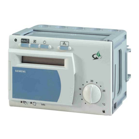
Function button with LED for man- Manual operation ON / OFF ual operation Green function ON / OFF Green function button with LED Info button Display of plant values Service connector 28/348 Siemens Building Technologies Basic Documentation RVP540 / RVP550 CE1P2488en HVAC Products Handling 18.10.2002... -
Page 29: Operating Procedure
“Configuration“). If a partial diagram group is not available (partial diagram 0), the relevant parameter Nonavailable blocks on the various levels will be hidden. parameter blocks 29/348 Siemens Building Technologies Basic Documentation RVP540 / RVP550 CE1P2488en HVAC Products Handling 18.10.2002... -
Page 30: Parameter Settings For The Enduser
"Enduser”. display Note: If no button is pressed for about 8 minutes, the con- troller will automatically return to the operating mode selected last. 30/348 Siemens Building Technologies Basic Documentation RVP540 / RVP550 CE1P2488en HVAC Products Handling 18.10.2002... -
Page 31: Overview Of Enduser Parameters
0 / 1 – To reset the parameters of the enduser level to their default values, press the + / - buttons simultaneously for 3 seconds. 31/348 Siemens Building Technologies Basic Documentation RVP540 / RVP550 CE1P2488en HVAC Products Handling 18.10.2002... - Page 32 Acknowledgement of heat pump error messages 135 0 / 1 – and 137 To reset error messages 135 and 137, press the + / - buttons si- multaneously for 3 seconds. 32/348 Siemens Building Technologies Basic Documentation RVP540 / RVP550 CE1P2488en HVAC Products Handling 18.10.2002...
-
Page 33: Parameter Settings For The Heating Engineer
Note: If no button is pressed for about 8 minutes, the con- troller will automatically return to the operating mode selected last. 33/348 Siemens Building Technologies Basic Documentation RVP540 / RVP550 CE1P2488en HVAC Products Handling 18.10.2002... -
Page 34: Overview Of Heating Engineer Parameters
0 / 1 – Without sensor B71 With sensor B71 Reduction water / brine sensor B11 0 / 1 – Without sensor B11 With sensor B11 34/348 Siemens Building Technologies Basic Documentation RVP540 / RVP550 CE1P2488en HVAC Products Handling 18.10.2002... - Page 35 Solar flow temperature sensor B64 for yield measure- 101...109 – - - - ment (ZuFu14) - - - None 101...109 Sensor B64 connected to sensor terminal B101...109 35/348 Siemens Building Technologies Basic Documentation RVP540 / RVP550 CE1P2488en HVAC Products Handling 18.10.2002...
- Page 36 Display of diagram identification number part 2 0...99‘999‘999 – – Display of diagram identification number part 3 0...99‘999‘999 – – Display of diagram identification number part 4 0...99‘999‘999 – – 36/348 Siemens Building Technologies Basic Documentation RVP540 / RVP550 CE1P2488en HVAC Products Handling 18.10.2002...
- Page 37 No value available Setpoint of minimum limitation of the return temperature °C Line 280 ...95 Actual value of return temperature B7 -50...350 °C – No value available 37/348 Siemens Building Technologies Basic Documentation RVP540 / RVP550 CE1P2488en HVAC Products Handling 18.10.2002...
- Page 38 – No value available Temperature differential collector 1 / swimming pool -50...350 No value available Temperature differential collector 2 / swimming pool -50...350 No value available 38/348 Siemens Building Technologies Basic Documentation RVP540 / RVP550 CE1P2488en HVAC Products Handling 18.10.2002...
- Page 39 Actual value of solar flow temperature B63 –50...350 °C – No value available Actual value of solar return temperature B64 –50...350 °C – No value available 39/348 Siemens Building Technologies Basic Documentation RVP540 / RVP550 CE1P2488en HVAC Products Handling 18.10.2002...
- Page 40 Display of speed of pump Q10 of the wood-fired boiler 0...100 – Minimum speed of pump of the wood-fired boiler 0…line 392 Maximum speed of pump of the wood-fired boiler Line 391…100 40/348 Siemens Building Technologies Basic Documentation RVP540 / RVP550 CE1P2488en HVAC Products Handling 18.10.2002...
- Page 41 --- / 0...4 – No test Everything OFF Q8 ON (brine pump) Q8+Q9 ON (plus heat pump circulator) Q8+Q9+K1 ON (plus stage 1) Q8+Q9+K1+K2 ON (plus stage 2) 41/348 Siemens Building Technologies Basic Documentation RVP540 / RVP550 CE1P2488en HVAC Products Handling 18.10.2002...
- Page 42 Sensor B4 Sensor B41 Sensor B42 Electrical immersion heater Release of outside temperature for electric immersion --- / –30...30 °C –5 heater buffer storage tank Function deactivated 42/348 Siemens Building Technologies Basic Documentation RVP540 / RVP550 CE1P2488en HVAC Products Handling 18.10.2002...
- Page 43 Transfer strategy in the winter 0...2 – For frost protection only According to d.h.w. heating Always Temperature differential ON transfer Line 535…40 °C Temperature differential OFF transfer 0…line 534 °C 43/348 Siemens Building Technologies Basic Documentation RVP540 / RVP550 CE1P2488en HVAC Products Handling 18.10.2002...
- Page 44 D.h.w. with lag heat source if released, lead heat source controls d.h.w. heating to space heating setpoint D.h.w. heating with lag heat source if released, lead heat source during d.h.w. heating OFF 44/348 Siemens Building Technologies Basic Documentation RVP540 / RVP550 CE1P2488en HVAC Products Handling...
- Page 45 - - - No test Everything OFF Heating circuit pump ON (Q2) In addition, mixing valve CLOSED (Q2 + Y2) In addition, mixing valve OPEN (Q2 + Y1) 45/348 Siemens Building Technologies Basic Documentation RVP540 / RVP550 CE1P2488en HVAC Products Handling 18.10.2002...
- Page 46 Periodicity of the legionella function --- / 1...7 – 1...7 Period of time / weekday Legionella function strategy 1...3 – Maximum period Fixed period Fixed weekday 46/348 Siemens Building Technologies Basic Documentation RVP540 / RVP550 CE1P2488en HVAC Products Handling 18.10.2002...
- Page 47 Heat generation lock heat pump Fault heat pump Fault wood-fired boiler Yield measurement solar Minimum flow temperature setpoint contact H1 (TVHw) 8...TKmax °C If activated at input H1 (setting 3) 47/348 Siemens Building Technologies Basic Documentation RVP540 / RVP550 CE1P2488en HVAC Products Handling 18.10.2002...
- Page 48 – fault values To reset the parameters of the heating engineer level to their default values, press the + / - buttons simultaneously for 3 seconds 48/348 Siemens Building Technologies Basic Documentation RVP540 / RVP550 CE1P2488en HVAC Products Handling 18.10.2002...
-
Page 49: Parameter Settings For The Expert
7 8 9 10 Whether correct or incorrect, each push of a button represents irrevocably a digit of the code. As an acknowledgement, the respective digit changes to 1. 49/348 Siemens Building Technologies Basic Documentation RVP540 / RVP550 CE1P2488en HVAC Products Handling... -
Page 50: Overview Of Exp Parameters
- - - Frost protection OFF Maximum storage tank charging time 1...60 Maximum waiting time 1...40 Changeover / startup delay bypass valve / charging 1...15 pump K9 50/348 Siemens Building Technologies Basic Documentation RVP540 / RVP550 CE1P2488en HVAC Products Handling 18.10.2002... - Page 51 Switching differential for minimum water / brine tem- 1...10 perature Buffer storage tank EXP Buffer storage tank safety temperature 20...95 °C D.h.w. storage tank EXP D.h.w. storage tank safety temperature 20...95 °C 51/348 Siemens Building Technologies Basic Documentation RVP540 / RVP550 CE1P2488en HVAC Products Handling 18.10.2002...
- Page 52 To reset the parameters of the EXP level to their default values, pres the + / - buttons simultaneously for 3 seconds Display of version of the basic diagram table 0...32‘767 – – 52/348 Siemens Building Technologies Basic Documentation RVP540 / RVP550 CE1P2488en HVAC Products Handling 18.10.2002...
-
Page 53: Operational Faults
• Check setting of the electromechanical control thermostat (TR) installed on the boiler. It must be above the TKmax setting. • Make “Functional test d.h.w.” (operating line 545) to see if the relevant relays will be energized. 53/348 Siemens Building Technologies Basic Documentation RVP540 / RVP550 CE1P2488en HVAC Products Handling... - Page 54 Select operating line 50. There, you can see the error code and the address of the af- fected device. Refer to section "Indication of errors" for a list of the possible error codes and their descriptions. 54/348 Siemens Building Technologies Basic Documentation RVP540 / RVP550 CE1P2488en HVAC Products Handling 18.10.2002...
-
Page 55: Description Of The Enduser Settings
Heating OFF Room temperature setpoint according to the frost protection level Protective functions active Operating actions on the room unit not possible 55/348 Siemens Building Technologies Basic Documentation RVP540 / RVP550 CE1P2488en HVAC Products Description of the enduser settings 18.10.2002... - Page 56 Changeover of the operating mode on the room unit is active only if the controller is in automatic mode The room temperature is transmitted to the controller via PPS, independent of the se- lected operating mode. 56/348 Siemens Building Technologies Basic Documentation RVP540 / RVP550 CE1P2488en HVAC Products Description of the enduser settings...
-
Page 57: Operating Mode Of D.h.w. Heating
(refer to operating line 779), the only difference being manual triggering. The manual d.h.w. push is triggered by pressing the d.h.w. operating mode button for more than 3 seconds. As a confirmation, the d.h.w. LED flashes briefly. 57/348 Siemens Building Technologies Basic Documentation RVP540 / RVP550 CE1P2488en HVAC Products Description of the enduser settings 18.10.2002... -
Page 58: Nominal Room Temperature Setpoint
24 h During the heating periods, the nominal room temperature setpoint is maintained. The heating periods are in accordance with the time switch program. 58/348 Siemens Building Technologies Basic Documentation RVP540 / RVP550 CE1P2488en HVAC Products Description of the enduser settings... -
Page 59: Temperature Adjustment Via The Room Unit
In the event of a power failure during manual operation, the controller will resume man- ual operation as soon as power is restored. 59/348 Siemens Building Technologies Basic Documentation RVP540 / RVP550 CE1P2488en HVAC Products Description of the enduser settings... - Page 60 Also displayed are the current info value, the relay statuses and the bus status. Manual operation should only be used temporarily in the event of faults. Note 60/348 Siemens Building Technologies Basic Documentation RVP540 / RVP550 CE1P2488en HVAC Products Description of the enduser settings 18.10.2002...
-
Page 61: Green Mode
Green operation via H1 If green operation is triggered via input H1 (operating line 870), the LED will flash and the green button is locked. 61/348 Siemens Building Technologies Basic Documentation RVP540 / RVP550 CE1P2488en HVAC Products Description of the enduser settings... -
Page 62: Info Button
Water / brine temperature heat pump [°C] Swimming pool temperature °C Display Example: display of the outside temperature (Info value 1): 9 10 62/348 Siemens Building Technologies Basic Documentation RVP540 / RVP550 CE1P2488en HVAC Products Description of the enduser settings 18.10.2002... -
Page 63: Setting The Clock
Thursday Date (day / month) and year Operating line Setting range Unit 01.01...31.12 Weekday month Operating line Setting range Unit 2001...2094 Year 63/348 Siemens Building Technologies Basic Documentation RVP540 / RVP550 CE1P2488en HVAC Products Description of the enduser settings 18.10.2002... -
Page 64: Time Switch Program For Space Heating
Tip First, choose the 7-day block (1-7) to enter the switching times that apply to most days; then, select the individual days (1...7) to make the required adjustments. 64/348 Siemens Building Technologies Basic Documentation RVP540 / RVP550 CE1P2488en HVAC Products Description of the enduser settings 18.10.2002... -
Page 65: Switching Times
The table below shows at what times which setpoints will be activated. Entry: – – : – – Switching point inactive. 00:00...24:00 At the time entered, heating to the respective temperature is ensured. 65/348 Siemens Building Technologies Basic Documentation RVP540 / RVP550 CE1P2488en HVAC Products Description of the enduser settings 18.10.2002... -
Page 66: Free Time Switch Program
See "Program overview" • • • below Important First, select the weekday (operating line 12) for which the switching times shall be en- tered! 66/348 Siemens Building Technologies Basic Documentation RVP540 / RVP550 CE1P2488en HVAC Products Description of the enduser settings 18.10.2002... -
Page 67: Time Switch Program For D.h.w. Heating
Example: The principle is the same as that used with "Time switch program space heating" (refer to the diagrams and the tip on page 64). 67/348 Siemens Building Technologies Basic Documentation RVP540 / RVP550 CE1P2488en HVAC Products Description of the enduser settings... -
Page 68: Switching Times
A setting example could look as follows: [°C] t [h] Nominal setpoint TBWw of the d.h.w. temperature Reduced setpoint TBW of the d.h.w. temperature 68/348 Siemens Building Technologies Basic Documentation RVP540 / RVP550 CE1P2488en HVAC Products Description of the enduser settings 18.10.2002... -
Page 69: Values
771, 773 and 774. Note In the event of a sensor with an open-circuit, the d.h.w. will not be heated (risk of scalding). 69/348 Siemens Building Technologies Basic Documentation RVP540 / RVP550 CE1P2488en HVAC Products Description of the enduser settings 18.10.2002... -
Page 70: Heating Circuit Values
Example The heating periods are in accordance with the settings made on lines 6 to 11. 24 h 70/348 Siemens Building Technologies Basic Documentation RVP540 / RVP550 CE1P2488en HVAC Products Description of the enduser settings 18.10.2002... -
Page 71: Frost Protection Setpoint Of The Room Temperature (Trfw)
856) • This function only acts in automatic mode and standby mode • During summer operation, the display shows ECO 71/348 Siemens Building Technologies Basic Documentation RVP540 / RVP550 CE1P2488en HVAC Products Description of the enduser settings 18.10.2002... - Page 72 SoWi -1 °C Changeover between summer and winter operation: Taged Attenuated outside temperature SoWi Summer / winter changeover temperature Temperature Time in days Heating 72/348 Siemens Building Technologies Basic Documentation RVP540 / RVP550 CE1P2488en HVAC Products Description of the enduser settings 18.10.2002...
-
Page 73: Heating Curve Slope
The actual value of the room temperature will automatically be displayed on this oper- ating line. Setting Display Unit 0...50 °C °C Special displays – – – Sensor with open-circuit or no room sensor connected 73/348 Siemens Building Technologies Basic Documentation RVP540 / RVP550 CE1P2488en HVAC Products Description of the enduser settings 18.10.2002... -
Page 74: General
The standard time program is activated as soon as the display changes to 1. Display Unit 0 / 1 In that case, the individual settings will be lost! Caution 74/348 Siemens Building Technologies Basic Documentation RVP540 / RVP550 CE1P2488en HVAC Products Description of the enduser settings 18.10.2002... -
Page 75: Holiday Program
Effect with room unit: The holiday function of the room unit is taken into consideration but the entries made on the controller are given priority. 75/348 Siemens Building Technologies Basic Documentation RVP540 / RVP550 CE1P2488en HVAC Products Description of the enduser settings... -
Page 76: Preselection Of Holiday Periods
151). The alarm output can be reset by pressing the + / - buttons simultaneously for 3 seconds (operating line 50). But the error in the error list remains. 76/348 Siemens Building Technologies Basic Documentation RVP540 / RVP550 CE1P2488en... - Page 77 Missing heat pump feedback signal via E1 Control sensor heat pump (operating line 420) delivers no signal * Wrong type of PPS device (BMU / room unit) 77/348 Siemens Building Technologies Basic Documentation RVP540 / RVP550 CE1P2488en HVAC Products Description of the enduser settings...
- Page 78 − Display Example of a display after an error has occurred: (external errors) 9 10 Additional errors can be displayed by pressing 78/348 Siemens Building Technologies Basic Documentation RVP540 / RVP550 CE1P2488en HVAC Products Description of the enduser settings 18.10.2002...
-
Page 79: Chimney Sweep
The + / - buttons can now be used to switch the second burner stage on or off. Note The chimney sweep function can also be activated via LPB (ACS69). 79/348 Siemens Building Technologies Basic Documentation RVP540 / RVP550 CE1P2488en HVAC Products Description of the enduser settings... -
Page 80: Solar Collectors
(e.g. replacement of a dirty filter, or replacement of a faulty pump). Note Error messages 135 and 137 will automatically be reset after 6 hours (activation of op- erating line 415 80/348 Siemens Building Technologies Basic Documentation RVP540 / RVP550 CE1P2488en HVAC Products Description of the enduser settings... -
Page 81: Description Of The Heating Engineer Settings
The key to the meaning of the individual numbers is given in document CE1P2489en (2 heat sources) or docu- ment CE1P2490en (3 heat sources). 81/348 Siemens Building Technologies Basic Documentation RVP540 / RVP550 CE1P2488en HVAC Products Description of the heating engineer settings 18.10.2002... -
Page 82: Configuration
/ gas-fired boiler will be supplied later. 1...9 Partial diagrams according to the partial diagram library (documents CE1P2489en and CE1P2490en). 82/348 Siemens Building Technologies Basic Documentation RVP540 / RVP550 CE1P2488en HVAC Products Description of the heating engineer settings... -
Page 83: Selection Of Partial Diagram "Solar Collectors
1...16 Partial diagrams according to the partial diagram library (documents CE1P2489en and CE1P2490en). 83/348 Siemens Building Technologies Basic Documentation RVP540 / RVP550 CE1P2488en HVAC Products Description of the heating engineer settings... -
Page 84: Selection Of Partial Diagram "Wood-Fired Boiler
1...5 Partial diagrams according to the partial diagram library (documents CE1P2489en and CE1P2490en). 84/348 Siemens Building Technologies Basic Documentation RVP540 / RVP550 CE1P2488en HVAC Products Description of the heating engineer settings... -
Page 85: Display Of Partial Diagram "Buffer Storage Tank
(without Q3): BwSp 4 BwSp 1 BwSp 5 BwSp 2 BwSp 6 BwSp 3 BwSp 9 BwSp 7 BwSp 10 BwSp 8 85/348 Siemens Building Technologies Basic Documentation RVP540 / RVP550 CE1P2488en HVAC Products Description of the heating engineer settings 18.10.2002... -
Page 86: Display Of Partial Diagram "Combi Storage Tank
No partial diagram selected. Parameter block “Heating circuit“ will be hidden. 1...3 Partial diagrams according to the partial diagram library (documents CE1P2489en and CE1P2490en). 86/348 Siemens Building Technologies Basic Documentation RVP540 / RVP550 CE1P2488en HVAC Products Description of the heating engineer settings 18.10.2002... -
Page 87: Hiding Sensors That Are Not Required
The d.h.w. sensor at B3 is activated. Note When using a BMU (PPS or LPB) with integrated d.h.w. heating, sensor B3 can be omitted. 87/348 Siemens Building Technologies Basic Documentation RVP540 / RVP550 CE1P2488en HVAC Products Description of the heating engineer settings... -
Page 88: Reduction Second D.h.w. Storage Tank Temperature Sensor B31
The return temperature sensor of the wood-fired boiler at B72 is deactivated. This means that the relevant sensor terminal becomes available for other use. The return temperature sensor of the wood-fired boiler at B72 is activated. 88/348 Siemens Building Technologies Basic Documentation RVP540 / RVP550 CE1P2488en HVAC Products Description of the heating engineer settings 18.10.2002... -
Page 89: Reduction Heat Pump Flow Temperature Sensor B21
The water / brine temperature sensor at B11 is deactivated. This means that the relevant sensor terminal becomes available for other use. The water / brine temperature sensor at B11 is activated. 89/348 Siemens Building Technologies Basic Documentation RVP540 / RVP550 CE1P2488en HVAC Products Description of the heating engineer settings 18.10.2002... -
Page 90: Auxiliary Functions
Y15 is deenergized, relay Y¯15 will be energized with a delay of 1 second, and vice versa. No assignment made. 90/348 Siemens Building Technologies Basic Documentation RVP540 / RVP550 CE1P2488en HVAC Products Description of the heating engineer settings... - Page 91 Return diversion can be integrated in the plant diagram as follows: Example: Sp 2 Sol 6 ZuFu 1 Y15 (Y 15) 91/348 Siemens Building Technologies Basic Documentation RVP540 / RVP550 CE1P2488en HVAC Products Description of the heating engineer settings 18.10.2002...
-
Page 92: Partial Storage Tank Y14 / Y¯14 / B43 (Zufu2)
When the temperature at sensor B43 drops 2 K below the storage tank setpoint, the diverting valve will change back to “an- gle” (partial charging of storage tank). 92/348 Siemens Building Technologies Basic Documentation RVP540 / RVP550 CE1P2488en HVAC Products Description of the heating engineer settings 18.10.2002... - Page 93 Partial storage tank charging (buffer storage tank) can be integrated in the diagram as follows: Example: Sp 2 Y14 (Y 14) ZuFu 2 93/348 Siemens Building Technologies Basic Documentation RVP540 / RVP550 CE1P2488en HVAC Products Description of the heating engineer settings 18.10.2002...
-
Page 94: Storage Tank Transfer Pump Q11 (Zufu3)
193), and transfer pump Q11 is used in place of the previous charging pump Q3. Example: BwSp 4 OeG 1 Sp 2 ZuFu 3 94/348 Siemens Building Technologies Basic Documentation RVP540 / RVP550 CE1P2488en HVAC Products Description of the heating engineer settings 18.10.2002... -
Page 95: Circulating Pump Q4 (Zufu4)
Application example The d.h.w. circulating pump can be integrated in the diagram as follows: Example: BwSp 3 ZuFu 4 95/348 Siemens Building Technologies Basic Documentation RVP540 / RVP550 CE1P2488en HVAC Products Description of the heating engineer settings 18.10.2002... -
Page 96: Additional Pump Q17 For Heat Pump Stage 2 (Zufu5)
An additional pump for the second heat pump stage Q17 can be integrated in the plant diagram as follows: Example: Wp 4 ZuFu 5 96/348 Siemens Building Technologies Basic Documentation RVP540 / RVP550 CE1P2488en HVAC Products Description of the heating engineer settings 18.10.2002... -
Page 97: System Pump Q14 (Zufu6)
Example of integration before / after the d.h.w. storage tank Rh 3 ZuFu 6 BwSp 3 BwSp 3 ZuFu 6 Y1/Y2 97/348 Siemens Building Technologies Basic Documentation RVP540 / RVP550 CE1P2488en HVAC Products Description of the heating engineer settings 18.10.2002... -
Page 98: Pump H1 Q15 (Zufu7)
Application example Pump H1 can be integrated in the diagram as follows: Example: Rh 3 ZuFu 7 Y1/Y2 (H1) 98/348 Siemens Building Technologies Basic Documentation RVP540 / RVP550 CE1P2488en HVAC Products Description of the heating engineer settings 18.10.2002... -
Page 99: Alarm Output K10 (Zufu8)
(refer to operating line 50) and if there is no other error with the nec- essary priority. Application example The alarm output can be integrated in the connection diagram as follows: Example: ZuFu 8 99/348 Siemens Building Technologies Basic Documentation RVP540 / RVP550 CE1P2488en HVAC Products Description of the heating engineer settings 18.10.2002... -
Page 100: Output "Overtemperature Protection K11 / K¯11" (Zufu9)
Application example Overtemperature protection is integrated in the connection diagram as follows: Example: ZuFu 9 K 11 100/348 Siemens Building Technologies Basic Documentation RVP540 / RVP550 CE1P2488en HVAC Products Description of the heating engineer settings 18.10.2002... -
Page 101: Relay K17 For The Flue Gas Temperature Function (Zufu10)
Integration into the plant diagram takes place according to the application example on operating line 155. Note For application examples, refer to operating lines 225 and 226. 101/348 Siemens Building Technologies Basic Documentation RVP540 / RVP550 CE1P2488en HVAC Products Description of the heating engineer settings... -
Page 102: Flue Gas Temperature Sensor B8 (Zufu10)
The flue gas temperature sensor can be integrated into the plant diagram as follows: Example: OeG 3 ZuFu 10 B8/K17 K4/K5 Y7/Y8 102/348 Siemens Building Technologies Basic Documentation RVP540 / RVP550 CE1P2488en HVAC Products Description of the heating engineer settings 18.10.2002... -
Page 103: Third Buffer Storage Tank Temperature Sensor B42 (Zufu11)
Application example The third buffer storage tank sensor can be integrated in the diagram as follows: Example: Sp 2 ZuFu 11 103/348 Siemens Building Technologies Basic Documentation RVP540 / RVP550 CE1P2488en HVAC Products Description of the heating engineer settings 18.10.2002... -
Page 104: Common Flow Temperature Sensor B10 (Zufu12)
The common flow temperature sensor can be integrated into the plant diagram as follows: Example: OeG 2 Rh 3 ZuFu 12 Y1/Y2 K4/K5 2392z15 104/348 Siemens Building Technologies Basic Documentation RVP540 / RVP550 CE1P2488en HVAC Products Description of the heating engineer settings 18.10.2002... -
Page 105: Solar Flow Temperature Sensor B62 (Zufu13)
The solar flow temperature sensor can be integrated in the diagram as follows: Integration Example A: Example B: Sol 3 BwSp 5 Sol 4 BwSp 5 ZuFu 13 ZuFu 13 2392z16 105/348 Siemens Building Technologies Basic Documentation RVP540 / RVP550 CE1P2488en HVAC Products Description of the heating engineer settings 18.10.2002... -
Page 106: Solar Flow Temperature Sensor B63 For Yield Measurement (Zufu14)
Application example Solar yield measurement can be integrated in the diagram as follows: Example: Sp 2 Sol 6 ZuFu 14 106/348 Siemens Building Technologies Basic Documentation RVP540 / RVP550 CE1P2488en HVAC Products Description of the heating engineer settings 18.10.2002... -
Page 107: Solar Return Temperature Sensor B64 For Yield Measurement (Zufu14)
As soon as this valve is deenergized, the valve returns to the initial position. For a valve with 2-wire control to change back to the initial position, a second inverted signal (K¯8) is required. 107/348 Siemens Building Technologies Basic Documentation RVP540 / RVP550 CE1P2488en HVAC Products Description of the heating engineer settings 18.10.2002... -
Page 108: Solar Diverting Valve K¯9 (Zufu16)
K¯9 can be assigned to the terminal with K9. In that case, K9 is re- placed by K¯9. Application example The diagram shows the inverted solar diverting valve K¯9 as follows: Example: ZuFu 16 108/348 Siemens Building Technologies Basic Documentation RVP540 / RVP550 CE1P2488en HVAC Products Description of the heating engineer settings 18.10.2002... -
Page 109: Output (K13) For The Free Time Switch Program (Zufu23)
The associated components will thereby be activated and deactivated. Application example The free time switch program can be depicted as follows: Example: ZuFu 23 109/348 Siemens Building Technologies Basic Documentation RVP540 / RVP550 CE1P2488en HVAC Products Description of the heating engineer settings 18.10.2002... -
Page 110: Electric Immersion Heater Buffer Storage Tank K16 (Zufu24)
The control sensor for reheating can be adjusted on operating line 485. Function “Reheating” can be deactivated on operating line 484. 110/348 Siemens Building Technologies Basic Documentation RVP540 / RVP550 CE1P2488en HVAC Products Description of the heating engineer settings... - Page 111 The electric immersion heater must be connected in series with a safety limit thermo- stat. Application example The electric immersion heater can be integrated in the diagram as follows: Example: Sp 2 ZuFu 24 111/348 Siemens Building Technologies Basic Documentation RVP540 / RVP550 CE1P2488en HVAC Products Description of the heating engineer settings 18.10.2002...
-
Page 112: Electric Immersion Heater K6 For The D.h.w. Storage Tank (Zufu25)
The electric immersion heater must be connected in series with a safety limit thermo- stat. Application example The electric immersion heater can be integrated in the diagram as follows: Example: BwSp 3 ZuFu 25 112/348 Siemens Building Technologies Basic Documentation RVP540 / RVP550 CE1P2488en HVAC Products Description of the heating engineer settings 18.10.2002... -
Page 113: Diverting Valve Q¯3 (Zufu26)
Q¯3 can be assigned to terminal Q3. In that case, Q3 will be re- placed by Q¯3. Application example The diagram shows the inverted d.h.w. diverting valve Q¯3 as follows: Example: ZuFu 26 113/348 Siemens Building Technologies Basic Documentation RVP540 / RVP550 CE1P2488en HVAC Products Description of the heating engineer settings 18.10.2002... -
Page 114: Heat Generation Lock Y4 / Y¯4 (Zufu27)
Important When a wood-fired boiler and heat generation lock Y4 are used simultaneously, heat consumption must be ensured with the valve in the changed position. 114/348 Siemens Building Technologies Basic Documentation RVP540 / RVP550 CE1P2488en HVAC Products Description of the heating engineer settings... - Page 115 The automatic heat generation lock can be integrated in the diagram as follows: Example: ZuFu 27 Y4 (Y 4) OeG 1 Sol 3 Sp 2 115/348 Siemens Building Technologies Basic Documentation RVP540 / RVP550 CE1P2488en HVAC Products Description of the heating engineer settings 18.10.2002...
-
Page 116: Solar Swimming Pool Heating K18 / K¯18 / B13 (Zufu28)
(K8, K9) – if present – and upstream of the heat exchanger. Parallel operation is not possible with solar collector partial diagrams Sol3, Sol8 and Sol12 through 16. 116/348 Siemens Building Technologies Basic Documentation RVP540 / RVP550 CE1P2488en HVAC Products Description of the heating engineer settings 18.10.2002... - Page 117 Sol 1 Sp 2 ZuFu 28 K18 (K 18) 2392Z57 Parallel Sol 1 Sp 2 ZuFu 28 K18 (K 18) 2392Z58 117/348 Siemens Building Technologies Basic Documentation RVP540 / RVP550 CE1P2488en HVAC Products Description of the heating engineer settings 18.10.2002...
- Page 118 (flow and return) are marked by a cross: Alternatively Parallel Sol 1 Sol 1 Sol 3 Sol 4 Sol 4 Sol 5 Sol 5 118/348 Siemens Building Technologies Basic Documentation RVP540 / RVP550 CE1P2488en HVAC Products Description of the heating engineer settings 18.10.2002...
- Page 119 Alternatively Parallel Sol 6 Sol 6 Sol 8 Sol 9 Sol 9 Sol 10 Sol 10 119/348 Siemens Building Technologies Basic Documentation RVP540 / RVP550 CE1P2488en HVAC Products Description of the heating engineer settings 18.10.2002...
- Page 120 Alternatively Parallel Sol 11 Sol 11 Sol 12 Sol 14 Sol 15 120/348 Siemens Building Technologies Basic Documentation RVP540 / RVP550 CE1P2488en HVAC Products Description of the heating engineer settings 18.10.2002...
-
Page 121: Miscellaneous
The diagram of a possible application can be found on operating line 146 (storage tank transfer pump). 121/348 Siemens Building Technologies Basic Documentation RVP540 / RVP550 CE1P2488en HVAC Products Description of the heating engineer settings 18.10.2002... -
Page 122: Setpoint And Time Switch Program For D.h.w. Heating With A Bmu
Note Auxiliary function “System pump” is to be activated on operating line 149. 122/348 Siemens Building Technologies Basic Documentation RVP540 / RVP550 CE1P2488en HVAC Products Description of the heating engineer settings... -
Page 123: General
Example of assigning relay Q15 to terminal 109: 9 10 The display of - - - means that the relevant terminal is not used. 123/348 Siemens Building Technologies Basic Documentation RVP540 / RVP550 CE1P2488en HVAC Products Description of the heating engineer settings... -
Page 124: Display Of Sensor Terminal Assignment
Example of assigning sensor B41 to terminal B102: 9 10 The display of - - - means that the relevant terminal is not used. 124/348 Siemens Building Technologies Basic Documentation RVP540 / RVP550 CE1P2488en HVAC Products Description of the heating engineer settings... -
Page 125: Display Of Configuration Errors
Combi storage tank (= 2 storage tanks) cannot be combined with another storage tank (not possible to have more than 2 storage tanks) B73, Y15 or Y¯15 is missing (ZuFu1, operating lines 140 and 141) 125/348 Siemens Building Technologies Basic Documentation RVP540 / RVP550 CE1P2488en HVAC Products Description of the heating engineer settings 18.10.2002... - Page 126 Overtemperature protection (ZuFu9) has been selected although no storage tank is used. The heat generation lock (ZuFu27) has been selected although there is neither a buffer nor a combi storage tank. 126/348 Siemens Building Technologies Basic Documentation RVP540 / RVP550 CE1P2488en HVAC Products Description of the heating engineer settings...
-
Page 127: Display Of Diagram Identification Numbers (Parts 1, 2, 3 And 4)
Diagram identification numbers (part 1) Diagram identification numbers (part 2) Diagram identification numbers (part 3) Diagram identification numbers (part 4) This number enables Siemens Building Technologies to unambiguously identify the Effect selected diagram. This facilitates the identification of problems and their communica- tion. -
Page 128: Terminal Test
The framed number indicates the selected setting line Timeout When there is no operating action, the output test will automatically be quit after 8 min- utes. 128/348 Siemens Building Technologies Basic Documentation RVP540 / RVP550 CE1P2488en HVAC Products Description of the heating engineer settings... -
Page 129: Input Test
(--- = no Signal, ooo = 230 V AC) The selected sensor values are updated within a maximum of 5 seconds. The display is made with no measured value correction. 129/348 Siemens Building Technologies Basic Documentation RVP540 / RVP550 CE1P2488en HVAC Products Description of the heating engineer settings 18.10.2002... -
Page 130: Display Of Pps Communication
Within the PPS, a fixed PPS address is assigned to some types of devices: Type of unit Assignment PPS-address Room unit 130/348 Siemens Building Technologies Basic Documentation RVP540 / RVP550 CE1P2488en HVAC Products Description of the heating engineer settings 18.10.2002... -
Page 131: Setpoint / Actual Value Of The Common Flow
The highest of the setpoints received is shown on the display as the flow temperature setpoint. Special displays – – – No value available 131/348 Siemens Building Technologies Basic Documentation RVP540 / RVP550 CE1P2488en HVAC Products Description of the heating engineer settings 18.10.2002... -
Page 132: Actual Value Of The Common Flow Temperature
Using the + / - buttons, the display can be reset to the current value. For that purpose, both buttons must be pressed simultaneously for 3 seconds. The value is reset as soon as the display stops flashing. 132/348 Siemens Building Technologies Basic Documentation RVP540 / RVP550 CE1P2488en HVAC Products Description of the heating engineer settings 18.10.2002... -
Page 133: Maximum Limitation Of The Flue Gas Temperature
Example of In this example, the switch-on point lies above the switch-off point. smoldering fire 133/348 Siemens Building Technologies Basic Documentation RVP540 / RVP550 CE1P2488en HVAC Products Description of the heating engineer settings... - Page 134 (Refer to operating line 225). Note Assignment of relay K17 to a free relay terminal is made on operating line 154. 134/348 Siemens Building Technologies Basic Documentation RVP540 / RVP550 CE1P2488en HVAC Products Description of the heating engineer settings...
-
Page 135: Oil- / Gas-Fired Boiler
• Preventing flue gas condensation in boilers not designed for it Benefit Description The setpoint of minimum limitation of the return temperature will automatically be dis- played on this operating line. 135/348 Siemens Building Technologies Basic Documentation RVP540 / RVP550 CE1P2488en HVAC Products Description of the heating engineer settings 18.10.2002... -
Page 136: Actual Value Of Return Temperature B7
The number of burner hours run can also be acquired via input E1 (operating lines 880 and 877). Resetting To reset the hours run meter to 0, press the + / - buttons simultaneously for 3 seconds. 136/348 Siemens Building Technologies Basic Documentation RVP540 / RVP550 CE1P2488en HVAC Products Description of the heating engineer settings... -
Page 137: Burner Hours Run Of Stage 2 (K5)
For calculating the average boiler running time, refer to operating line 257. Resetting To make a reset to 0 °C, press the + / - buttons simultaneously for 3 seconds. 137/348 Siemens Building Technologies Basic Documentation RVP540 / RVP550 CE1P2488en HVAC Products Description of the heating engineer settings 18.10.2002... -
Page 138: Functions
Tkmin Minimum limitation of the boiler temperature TKmax maximum limitation of the boiler temperature Switching differential TAgem Composite outside temperature °C 138/348 Siemens Building Technologies Basic Documentation RVP540 / RVP550 CE1P2488en HVAC Products Description of the heating engineer settings 18.10.2002... -
Page 139: Frost Protection For The Plant With The Boiler Pump
The BMU displays error code 175. Note If there is a BMU error code, operating line 50 also displays a general BMU error (error code 150). 139/348 Siemens Building Technologies Basic Documentation RVP540 / RVP550 CE1P2488en HVAC Products Description of the heating engineer settings... -
Page 140: Functional Test Of Oil- / Gas-Fired Boiler
The position of the mixing valve will only be defined with test steps 4 (ON) and 5 (OFF). The functional test will be terminated when leaving the operating line. 140/348 Siemens Building Technologies Basic Documentation RVP540 / RVP550 CE1P2488en HVAC Products Description of the heating engineer settings 18.10.2002... -
Page 141: Solar Collectors
Sensor B6 must always be located on the first collector, sensor B61 on the second collector, if installed. Sol 12 Sol 1 141/348 Siemens Building Technologies Basic Documentation RVP540 / RVP550 CE1P2488en HVAC Products Description of the heating engineer settings... -
Page 142: Actual Value Of Collector Flow Temperature B62
Resetting The maximum value of the collector temperature can be reset to the currently acquired collector temperature by simultaneously pressing the + / - buttons for 3 seconds. 142/348 Siemens Building Technologies Basic Documentation RVP540 / RVP550 CE1P2488en HVAC Products Description of the heating engineer settings 18.10.2002... -
Page 143: Temperature Differentials Collector / Heat Exchanger
– if present – will be used. In that case, operating line 50 will display an appropriate error message. Special displays – – – No value available 143/348 Siemens Building Technologies Basic Documentation RVP540 / RVP550 CE1P2488en HVAC Products Description of the heating engineer settings 18.10.2002... - Page 144 Based on these key data, the table delivers heat exchanger 1 with sensor B41 for the buffer storage tank and heat exchanger 2 with sensor B31 for the d.h.w. storage tank. 144/348 Siemens Building Technologies Basic Documentation RVP540 / RVP550 CE1P2488en...
-
Page 145: Temperature Differentials Collector / Swimming Pool
(collector 2 with sensor B61) Resetting To reset the hours run counter to 0, press the + / - buttons simultaneously for 3 sec- onds. 145/348 Siemens Building Technologies Basic Documentation RVP540 / RVP550 CE1P2488en HVAC Products Description of the heating engineer settings... -
Page 146: Hours Run Of Pump K12 / Diverting Valve K8
Number of operating hours of swimming pool heating (output K18). Resetting To reset the hours run counter to 0, press the + / - buttons simultaneously for 3 sec- onds. 146/348 Siemens Building Technologies Basic Documentation RVP540 / RVP550 CE1P2488en HVAC Products Description of the heating engineer settings... -
Page 147: Solar Swimming Pool Heating
B13 by the temperature differential adjusted on this op- erating line. But the swimming pool is heated only when charging is permitted by the selected pri- ority (operating line 333). 147/348 Siemens Building Technologies Basic Documentation RVP540 / RVP550 CE1P2488en HVAC Products Description of the heating engineer settings... -
Page 148: Temperature Differential Swimming Pool Off
Which of the storage tanks is charged first depends on the priority selected on op- erating line 333. 148/348 Siemens Building Technologies Basic Documentation RVP540 / RVP550 CE1P2488en HVAC Products Description of the heating engineer settings... -
Page 149: Measured Value Correction Swimming Pool Sensor B13
When entering a negative value, the temperature measured will be lowered by that value, when entering a positive value, it will be raised by that value. The readjusted temperature will be displayed on operating line 318. 149/348 Siemens Building Technologies Basic Documentation RVP540 / RVP550 CE1P2488en HVAC Products Description of the heating engineer settings 18.10.2002... -
Page 150: Functions
When entering a negative value, the temperature measured will be lowered by that value, when entering a positive value, it will be raised by that value. The corrected tem- peratures will be displayed on operating lines 300, 301 and 302. 150/348 Siemens Building Technologies Basic Documentation RVP540 / RVP550 CE1P2488en HVAC Products Description of the heating engineer settings 18.10.2002... -
Page 151: Heat Exchanger Pump Operation For Partial Diagram Sol 5
Actual value of the solar collector temperature when the storage tank temperature is constant maximum waiting time Pump of heat exchanger 1 Pump of heat exchanger 2 151/348 Siemens Building Technologies Basic Documentation RVP540 / RVP550 CE1P2488en HVAC Products Description of the heating engineer settings 18.10.2002... -
Page 152: Temperature Differential On Heat Exchanger
Pump of heat exchanger 1 Pump of heat exchanger 2 Actual value of the solar collector temperature when the storage tank temperature is constant 152/348 Siemens Building Technologies Basic Documentation RVP540 / RVP550 CE1P2488en HVAC Products Description of the heating engineer settings... -
Page 153: Temperature Differential Off Heat Exchanger
Pump of heat exchanger 1 Pump of heat exchanger 2 Actual value of the solar collector temperature when the storage tank temperature is constant 153/348 Siemens Building Technologies Basic Documentation RVP540 / RVP550 CE1P2488en HVAC Products Description of the heating engineer settings... -
Page 154: Priority With 2 Heat Exchangers
If neither the buffer nor the d.h.w. storage tank switch-on criterion is met, there will be no charging. 154/348 Siemens Building Technologies Basic Documentation RVP540 / RVP550 CE1P2488en HVAC Products Description of the heating engineer settings 18.10.2002... - Page 155 By charging or trans- ferring heat, the amount of heat contained in the buffer storage tank can also be used in the summer. 155/348 Siemens Building Technologies Basic Documentation RVP540 / RVP550 CE1P2488en HVAC Products Description of the heating engineer settings 18.10.2002...
-
Page 156: Solar Yield Measurement
To acquire the amount of heat supplied to the swimming pool, at least return tempera- ture sensor B64 (operating line 160) must be present. In connection with heat metering, swimming pool sensor B13 is not taken into consideration. 156/348 Siemens Building Technologies Basic Documentation RVP540 / RVP550 CE1P2488en HVAC Products Description of the heating engineer settings 18.10.2002... -
Page 157: Type Of Antifreeze Agent Added
Effect Setting 0 means that no antifreeze agent has been added. Setting 100 means that the solar circuit only contains nothing but antifreeze agent. 157/348 Siemens Building Technologies Basic Documentation RVP540 / RVP550 CE1P2488en HVAC Products Description of the heating engineer settings... -
Page 158: Pulse Value Flow Meter
This method does not work with speed-controlled solar pumps! This method delivers acceptable accuracy only if the effective volumetric flow in the solar circuit is accurately calculated or measured. 158/348 Siemens Building Technologies Basic Documentation RVP540 / RVP550 CE1P2488en HVAC Products Description of the heating engineer settings 18.10.2002... -
Page 159: Selection Of Type Of Sensor B63 And B64 For Solar Yield Measurement
Description Display of the actual temperature acquired with sensor B64 (solar yield measurement). Setting Setting range Unit Factory setting -50...350 °C 159/348 Siemens Building Technologies Basic Documentation RVP540 / RVP550 CE1P2488en HVAC Products Description of the heating engineer settings 18.10.2002... -
Page 160: Speed-Controlled Solar Pump
Temperature differential ON heat exchanger 330 / 332 Temperature differential OFF heat exchanger 346 /347 Minimum speed / maximum speed of the solar pump 160/348 Siemens Building Technologies Basic Documentation RVP540 / RVP550 CE1P2488en HVAC Products Description of the heating engineer settings 18.10.2002... -
Page 161: Display Of Speed Of The Solar Pump Q5 / K9
The minimum speed of the solar pump can be defined. It is thus possible to negate the lowest pump speeds, which cannot be properly controlled. Setting Setting range Unit Factory setting 0…line 347 161/348 Siemens Building Technologies Basic Documentation RVP540 / RVP550 CE1P2488en HVAC Products Description of the heating engineer settings 18.10.2002... -
Page 162: Maximum Speed Of The Solar Pump
Q5/K12 + Q16 + K9 ON Q5/K12 + Q16 +K9 + K8 ON Note The functional test will be terminated when quitting the operating line. 162/348 Siemens Building Technologies Basic Documentation RVP540 / RVP550 CE1P2488en HVAC Products Description of the heating engineer settings... -
Page 163: Wood-Fired Boiler
Setting Display Unit --- / -50...350 °C Special displays – – – No value available 163/348 Siemens Building Technologies Basic Documentation RVP540 / RVP550 CE1P2488en HVAC Products Description of the heating engineer settings 18.10.2002... -
Page 164: Hours Run Counter
– Resetting To reset the number of releases to 0, press the + / - buttons simultaneously for 3 sec- onds. 164/348 Siemens Building Technologies Basic Documentation RVP540 / RVP550 CE1P2488en HVAC Products Description of the heating engineer settings 18.10.2002... -
Page 165: Functions
Minimum limitation of the return temperature of wood-fired boilers Special displays – – – Minimum temperature differential of the wood-fired boiler OFF 165/348 Siemens Building Technologies Basic Documentation RVP540 / RVP550 CE1P2488en HVAC Products Description of the heating engineer settings... -
Page 166: Minimum Temperature Of The Wood-Fired Boiler For Release Of The Pump
• The pump has not been in operation for at least 15 minutes, the boiler temperature rises by at least 1 K / min and the minimum temperature differential of the wood- fired boiler (operating line 369) is satisfied 166/348 Siemens Building Technologies Basic Documentation RVP540 / RVP550 CE1P2488en HVAC Products Description of the heating engineer settings 18.10.2002... -
Page 167: Switching Differential Of "Minimum Temperature Of The Wood-Fired Boiler For Release Of The Pump
If, during the pump overrun time, the switch-on criteria are not satisfied again, the pump will be deactivated. Special displays – – – No pump overrun time 167/348 Siemens Building Technologies Basic Documentation RVP540 / RVP550 CE1P2488en HVAC Products Description of the heating engineer settings 18.10.2002... -
Page 168: Strategy For The Wood-Fired Boiler
A detailed description of boiler temperature setpoint generation and storage tank priority is given in the following section. 168/348 Siemens Building Technologies Basic Documentation RVP540 / RVP550 CE1P2488en HVAC Products Description of the heating engineer settings... -
Page 169: Generation Of Heat Demand (Setting 1)
Input H1 closed First, the buffer tank will be fully charged, then the (d.h.w. button not relevant) d.h.w. storage tank. 169/348 Siemens Building Technologies Basic Documentation RVP540 / RVP550 CE1P2488en HVAC Products Description of the heating engineer settings 18.10.2002... -
Page 170: Wood-Fired Boiler Locks Other Heat Sources
(378) has no impact. A detailed description of the impact of frost protection for the plant is given on operating line 180 170/348 Siemens Building Technologies Basic Documentation RVP540 / RVP550 CE1P2488en HVAC Products Description of the heating engineer settings 18.10.2002... -
Page 171: Residual Heat Function
The temperature differential between boiler temperature and return temperature sensor may then start to increase again. If desired, this residual heat can be utilized by repeat- edly activating the residual heat function (operating line 386). 171/348 Siemens Building Technologies Basic Documentation RVP540 / RVP550 CE1P2488en HVAC Products Description of the heating engineer settings 18.10.2002... -
Page 172: Residual Heat Function Performed Once / Several Times
As long as residual heat is available, it will be delivered into the buffer storage tank. In that case, the buffer storage tank’s stratification will not be taken into consideration. 172/348 Siemens Building Technologies Basic Documentation RVP540 / RVP550 CE1P2488en... -
Page 173: Residual Heat Function Directly For The Consumers
(operating line 387) and the “Minimum temperature differential of the wood-fired boiler” (operating line 369) are inactive. 173/348 Siemens Building Technologies Basic Documentation RVP540 / RVP550 CE1P2488en HVAC Products Description of the heating engineer settings... -
Page 174: Speed-Controlled Pump Of Wood-Fired Boiler
Setting Setting range Unit Factory setting min…100 Boiler pump, minimum speed of the pump, operating line 391 174/348 Siemens Building Technologies Basic Documentation RVP540 / RVP550 CE1P2488en HVAC Products Description of the heating engineer settings 18.10.2002... -
Page 175: Diagnosis
Description The current heat pump flow temperature setpoint will automatically be displayed on this operating line. Setting Display Unit 0...140 °C 175/348 Siemens Building Technologies Basic Documentation RVP540 / RVP550 CE1P2488en HVAC Products Description of the heating engineer settings 18.10.2002... -
Page 176: Actual Value Of The Heat Pump Flow Temperature B21
The actual value of the water / brine flow temperature will automatically be displayed on this operating line. Setting Display Unit –50...350 °C Effect If the display shows "---", there is no value available. 176/348 Siemens Building Technologies Basic Documentation RVP540 / RVP550 CE1P2488en HVAC Products Description of the heating engineer settings 18.10.2002... -
Page 177: Hours Run Counter
413) Resetting To reset the hours run counter to 0, press the + / - buttons simultaneously for 3 sec- onds. 177/348 Siemens Building Technologies Basic Documentation RVP540 / RVP550 CE1P2488en HVAC Products Description of the heating engineer settings 18.10.2002... -
Page 178: Number Of Starts Of Heat Pump Stage 1 (K1)
For calculating the average running time of heat pump stage 2, refer to operating line 411. Resetting To reset the start counter to 0, press the + / - buttons simultaneously for 3 seconds. 178/348 Siemens Building Technologies Basic Documentation RVP540 / RVP550 CE1P2488en HVAC Products Description of the heating engineer settings... -
Page 179: Functions
If the setpoint of return temperature sensor B71 is required (settings 2, 4, 5, 8 and 9), the correct “Temperature differential of flow and return at –10 °C" must be entered (op- erating line 423). 179/348 Siemens Building Technologies Basic Documentation RVP540 / RVP550 CE1P2488en HVAC Products Description of the heating engineer settings 18.10.2002... -
Page 180: Heat Pump Switching Differential On
/ heat deficit (operating line 416 ) can significantly delay the switch-on / off point (according to switching differentials ON and OFF, operating lines 421 and 422). 180/348 Siemens Building Technologies Basic Documentation RVP540 / RVP550 CE1P2488en HVAC Products Description of the heating engineer settings 18.10.2002... -
Page 181: Flow / Return Temperature Differential At -10 °C
30.00 25.00 20.00 °C 20.00 18.00 16.00 14.00 12.00 10.00 8.00 6.00 4.00 2.00 0.00 -2.00 -4.00 -6.00 -8.00 -10.00 Aussentemperatur 181/348 Siemens Building Technologies Basic Documentation RVP540 / RVP550 CE1P2488en HVAC Products Description of the heating engineer settings 18.10.2002... -
Page 182: Compensation Of Mixing Valve Boost
(426) has no impact. A detailed description of the impact of frost protection on the plant is given on operating line 180 182/348 Siemens Building Technologies Basic Documentation RVP540 / RVP550 CE1P2488en HVAC Products Description of the heating engineer settings 18.10.2002... -
Page 183: Additional Pump Kick For Water / Brine Pump
The heat pump circulators will operate when there is demand for heat. The relevant heat pump circulator will operate when the respective heat pump stage is in operation (prerun and overrun are taken into consideration). 183/348 Siemens Building Technologies Basic Documentation RVP540 / RVP550 CE1P2488en HVAC Products Description of the heating engineer settings 18.10.2002... -
Page 184: Diagnosis
In addition, heat pump stage 2 ON (Q8 + Q9 + K1 + K2) Note The functional test will be terminated when leaving the operating line. 184/348 Siemens Building Technologies Basic Documentation RVP540 / RVP550 CE1P2488en HVAC Products Description of the heating engineer settings... -
Page 185: Buffer Storage Tank
If the 2 auxiliary functions ZuFu2 and ZuFu11 are used at the same time and make use of the same sensor, the sensor must be connected in parallel to both terminals. Natu- rally, the display of B42 and B43 will then be identical. 185/348 Siemens Building Technologies Basic Documentation RVP540 / RVP550 CE1P2488en HVAC Products Description of the heating engineer settings 18.10.2002... -
Page 186: Maximum Value Of Buffer Storage Tank Sensor B4
Resetting To set the setpoint of the buffer storage tank temperature (slave pointer) to the current heat demand, press the + / - buttons simultaneously for 3 seconds. 186/348 Siemens Building Technologies Basic Documentation RVP540 / RVP550 CE1P2488en HVAC Products Description of the heating engineer settings 18.10.2002... -
Page 187: Functions
If B4 (top) drops 2 K below the required temperature, the buffer storage tank will be charged until the temperature at sensor B41 (bottom) reaches the tem- perature displayed on operating line 456 (slave pointer). 187/348 Siemens Building Technologies Basic Documentation RVP540 / RVP550 CE1P2488en HVAC Products Description of the heating engineer settings 18.10.2002... -
Page 188: Minimum Buffer Storage Tank Temperature Level When Charging With The Collectors (Tpmin)
B6/B61 Collector temperature 1 / 2 Actual value of buffer storage tank temperature Q5/Q16/K12 Collector pumps Collector pump or diverting valve 188/348 Siemens Building Technologies Basic Documentation RVP540 / RVP550 CE1P2488en HVAC Products Description of the heating engineer settings 18.10.2002... -
Page 189: Maximum Buffer Storage Tank Charging Temperature
If d.h.w. charging by the buffer storage tank is desired, function “Automatic transfer” (operating lines 530 through 535) can be appropriately set. 189/348 Siemens Building Technologies Basic Documentation RVP540 / RVP550 CE1P2488en HVAC Products Description of the heating engineer settings 18.10.2002... -
Page 190: Δt Differential Between Buffer Storage Tank Temperature And Heat Demand From The Heating Circuit
Slave pointer / B4 Forced charging takes place until, at buffer storage tank sensor B4, the value of the slave pointer is reached (see chapter 6, “Functions with no setting”). 190/348 Siemens Building Technologies Basic Documentation RVP540 / RVP550 CE1P2488en HVAC Products Description of the heating engineer settings 18.10.2002... - Page 191 ≠ 0), forced charging will be deactivated as soon as the “Central standby switch” (operating line 857) is set to 1 (ON). 191/348 Siemens Building Technologies Basic Documentation RVP540 / RVP550 CE1P2488en HVAC Products Description of the heating engineer settings...
-
Page 192: Return Diversion
The effect changeover depends on the mode of operation selected on operating line 482. For a description of the auxiliary function and a graph, refer to operating lines 140 and 141. 192/348 Siemens Building Technologies Basic Documentation RVP540 / RVP550 CE1P2488en HVAC Products Description of the heating engineer settings... -
Page 193: Operating Action Of The Return Diversion (Zufu1)
Buffer storage tank sensor B41 Buffer storage tank sensor B42 Note To ensure proper functioning, the sensors must be correctly located. 193/348 Siemens Building Technologies Basic Documentation RVP540 / RVP550 CE1P2488en HVAC Products Description of the heating engineer settings... -
Page 194: Electric Immersion Heater
Important For the frost protection function of the buffer storage tank, buffer storage tank sensor B4 is always used – independent of the selected control sensor. 194/348 Siemens Building Technologies Basic Documentation RVP540 / RVP550 CE1P2488en HVAC Products Description of the heating engineer settings... -
Page 195: Buffer Storage Tank Overtemperature
Maximum buffer storage tank temperature = operating line 450 – operating line 489 Actual value at the coldest buffer storage tank sensor 195/348 Siemens Building Technologies Basic Documentation RVP540 / RVP550 CE1P2488en HVAC Products Description of the heating engineer settings... -
Page 196: Difference Between The Maximum Storage Tank Temperature (Msp) And The Buffer Storage Tank Safety Temperature
Maximum buffer storage tank temperature = operating line 450 – operating line 489 Actual value at the buffer storage tank sensor at the bottom 196/348 Siemens Building Technologies Basic Documentation RVP540 / RVP550 CE1P2488en HVAC Products Description of the heating engineer settings... -
Page 197: Priority Of Buffer Storage Tank Cooling With The Transfer Pump
2 K (nonadjustable) Note If the storage tank has 2 heat exchangers, the heat exchanger at the bottom will be used for discharging. 197/348 Siemens Building Technologies Basic Documentation RVP540 / RVP550 CE1P2488en HVAC Products Description of the heating engineer settings... -
Page 198: Priority Of Buffer Storage Tank Cooling With The Heat Source Pump
The cooling function will be stopped (relay K11 will be deenergized) as soon as the se- lected priority is no longer released (refer to “Functioning” on page 195). 198/348 Siemens Building Technologies Basic Documentation RVP540 / RVP550 CE1P2488en HVAC Products Description of the heating engineer settings 18.10.2002... -
Page 199: Priority Of Buffer Storage Tank Cooling Through Delivery Of Heat For Space
The cooling function will be stopped as soon as the selected priority is no longer re- leased (refer to mode of operation on page 195). Important This function is only active in winter operation. 199/348 Siemens Building Technologies Basic Documentation RVP540 / RVP550 CE1P2488en HVAC Products Description of the heating engineer settings... -
Page 200: Heating 199 D.h.w. Storage Tank
The electric immersion heater will heat the d.h.w. in summer and winter opera- tion according to the switching times and time switch program of d.h.w. (oper- ating lines 770 through 795). 200/348 Siemens Building Technologies Basic Documentation RVP540 / RVP550 CE1P2488en HVAC Products Description of the heating engineer settings 18.10.2002... -
Page 201: Recharge Control Of The D.h.w. Storage Tank
B3 and one switching differential (operating line ); for charging in connection with the legionella function via the tem- peratures at sensors B3 and B31. 201/348 Siemens Building Technologies Basic Documentation RVP540 / RVP550 CE1P2488en HVAC Products Description of the heating engineer settings 18.10.2002... -
Page 202: Minimum D.h.w. Storage Tank Temperature Level When Charging With The Collector (Tbmin)
Collector temperature 1 / 2 Actual value of the d.h.w. storage tank temperature Q5/Q16/K12 Collector pumps Collector pump or diverting valve 202/348 Siemens Building Technologies Basic Documentation RVP540 / RVP550 CE1P2488en HVAC Products Description of the heating engineer settings 18.10.2002... -
Page 203: Maximum D.h.w. Storage Tank Charging Temperature
535), or when the d.h.w. storage tank has reached its setpoint. During “Automatic heat transfer”, no heat sources will be put into operation, unless the automatic or manual “D.h.w. push” has been activated. 203/348 Siemens Building Technologies Basic Documentation RVP540 / RVP550 CE1P2488en HVAC Products Description of the heating engineer settings 18.10.2002... -
Page 204: Heat Transfer With The D.h.w. Sensor
Defines when heat transfer in the summer is released. Heat transfer strategy winter Defines when heat transfer in the winter is released. 204/348 Siemens Building Technologies Basic Documentation RVP540 / RVP550 CE1P2488en HVAC Products Description of the heating engineer settings... -
Page 205: Heat Transfer Temperature Differential On
When the temperature differential drops below the value set here, automatic heat transfer will be stopped. The pump (Q3 or Q11) selected on operating line 531 will be deactivated. 205/348 Siemens Building Technologies Basic Documentation RVP540 / RVP550 CE1P2488en HVAC Products Description of the heating engineer settings 18.10.2002... -
Page 206: Overtemperature Protection D.h.w. Storage Tank
Maximum d.h.w. storage tank temperature = operating line 500 – operating line 539 Actual value of the storage tank temperature acquired by the sensor at the bottom of the tank 206/348 Siemens Building Technologies Basic Documentation RVP540 / RVP550 CE1P2488en HVAC Products Description of the heating engineer settings 18.10.2002... -
Page 207: Difference Between The Maximum Storage Tank Temperature (Msb) And The D.h.w. Storage Tank Safety Temperature
Maximum d.h.w. storage tank temperature = operating line 500 – operating line 539 Actual value of the storage tank temperature acquired by the sensor at the bottom of the tank 207/348 Siemens Building Technologies Basic Documentation RVP540 / RVP550 CE1P2488en HVAC Products Description of the heating engineer settings 18.10.2002... -
Page 208: Priority Of D.h.w. Storage Tank Cooling With The Heat Transfer Pump
2 K (nonadjustable) Note If the storage tank has 2 heat exchangers, the heat exchanger at the bottom will be used for cooling. 208/348 Siemens Building Technologies Basic Documentation RVP540 / RVP550 CE1P2488en HVAC Products Description of the heating engineer settings... -
Page 209: Priority Of D.h.w. Storage Tank Cooling With Overtemperature Protection Output K11
0 / 1 – Effect Sensor B31 is used for the functionality of B31. Sensor B31 is used for the functionality of B4. 209/348 Siemens Building Technologies Basic Documentation RVP540 / RVP550 CE1P2488en HVAC Products Description of the heating engineer settings 18.10.2002... -
Page 210: Bivalent Operation
The lag heat source will be switched on only when the amount of heat delivered by the lead heat source no longer meets the demand. This is checked with the release integral (operating line 622). 210/348 Siemens Building Technologies Basic Documentation RVP540 / RVP550 CE1P2488en HVAC Products Description of the heating engineer settings 18.10.2002... -
Page 211: Delayed Switching On Of Lag Heat Source
0...500 K*min Effect As soon as the adjusted amount of surplus heat is reached, the lag heat source will be locked. 211/348 Siemens Building Technologies Basic Documentation RVP540 / RVP550 CE1P2488en HVAC Products Description of the heating engineer settings 18.10.2002... -
Page 212: Release Depending On The Outside Temperature
Switching differential for switch-on / off outside temperature is fixed at 1 K Composite outside temperature (operating line 705) Examples: Bivalent-alternative °C Bivalent-partially-parallel °C 212/348 Siemens Building Technologies Basic Documentation RVP540 / RVP550 CE1P2488en HVAC Products Description of the heating engineer settings 18.10.2002... - Page 213 The switching points for release and locking are separated by a switching differential to absorb small outside temperature variations. Examples Refer to “Release of outside temperature” (before operating line 630). 213/348 Siemens Building Technologies Basic Documentation RVP540 / RVP550 CE1P2488en HVAC Products Description of the heating engineer settings...
-
Page 214: Release Of Heat Pump Above The Outside Temperature Threshold
The switching points for release and locking are separated by a switching differential to absorb small outside temperature variations. Examples Refer to “Release of outside temperature” (above operating line 630). 214/348 Siemens Building Technologies Basic Documentation RVP540 / RVP550 CE1P2488en HVAC Products Description of the heating engineer settings... -
Page 215: Heating
The lead heat source will be switched off. If the lag heat source is not released, the lead heat source will be switched on to adopt the setpoint for d.h.w. heating. 215/348 Siemens Building Technologies Basic Documentation RVP540 / RVP550 CE1P2488en HVAC Products Description of the heating engineer settings 18.10.2002... -
Page 216: Heating Circuit / Space Heating
In that case, the controller's setpoint knob is inactive. Important Setpoints and readjustments made on room units are considered only in automatic mode (on the controller). 216/348 Siemens Building Technologies Basic Documentation RVP540 / RVP550 CE1P2488en HVAC Products Description of the heating engineer settings 18.10.2002... -
Page 217: Display Of Room Temperature Setpoint Trw
When selecting the operating line, the display shows the actual value of the flow tem- perature (sensor B1). Setting Display Unit -50...350 °C Special displays – – – No value available 217/348 Siemens Building Technologies Basic Documentation RVP540 / RVP550 CE1P2488en HVAC Products Description of the heating engineer settings 18.10.2002... -
Page 218: Attenuated Outside Temperature Taxged
The attenuated outside temperature can be reset on operating line 34. TAakt Example °C TAged 18:00 06:00 18:00 06:00 18:00 TAakt Actual outside temperature TAged Attenuated outside temperature 218/348 Siemens Building Technologies Basic Documentation RVP540 / RVP550 CE1P2488en HVAC Products Description of the heating engineer settings 18.10.2002... -
Page 219: Composite Outside Temperature Taxgem
Actual outside temperature TAged Attenuated outside temperature TAgem1 Composite outside temperature for light building structures TAgem0 Composite outside temperature for heavy building structures 219/348 Siemens Building Technologies Basic Documentation RVP540 / RVP550 CE1P2488en HVAC Products Description of the heating engineer settings 18.10.2002... -
Page 220: Measured Value Correction Outside Sensor B9
Each setpoint readjustment, be it by changing the setting value or the operational level, corresponds to a parallel displacement of the heating curve. °C °C Flow temperature Composite outside temperature TRw Room temperature setpoint 220/348 Siemens Building Technologies Basic Documentation RVP540 / RVP550 CE1P2488en HVAC Products Description of the heating engineer settings 18.10.2002... -
Page 221: Room Influence
• The respective room unit must be connected to terminal A6 (PPS) • There may be no thermostatic radiator valves in the reference room (if such valves are present, they must be set to their fully open position). 221/348 Siemens Building Technologies Basic Documentation RVP540 / RVP550 CE1P2488en HVAC Products Description of the heating engineer settings 18.10.2002... -
Page 222: Switching Differential Of The Room Temperature (Sdr)
SDR Switching differential of the room temperature Switch-on point OFF Switch-off point Time Pump Switching differential Pump ON Pump OFF TRw + SDR 222/348 Siemens Building Technologies Basic Documentation RVP540 / RVP550 CE1P2488en HVAC Products Description of the heating engineer settings 18.10.2002... -
Page 223: Minimum Limitation Of The Flow Temperature Setpoint (Tvmin)
This may lead to exces- sive room temperatures. 223/348 Siemens Building Technologies Basic Documentation RVP540 / RVP550 CE1P2488en HVAC Products Description of the heating engineer settings 18.10.2002... -
Page 224: Maximum Limitation Of The Flow Temperature Setpoint (Tvmax)
• Heavy building structures: Building construction Buildings with thick walls or with external insulation • Light building structures: Buildings with a light envelope 224/348 Siemens Building Technologies Basic Documentation RVP540 / RVP550 CE1P2488en HVAC Products Description of the heating engineer settings 18.10.2002... -
Page 225: Adaption Of The Heating Curve
2 (operating line 710 • No adaption (range At attenuated outside temperatures above 12 °C, the heating curve will not be adapted. 225/348 Siemens Building Technologies Basic Documentation RVP540 / RVP550 CE1P2488en HVAC Products Description of the heating engineer settings... - Page 226 Factor for slope TAged Attenuated outside temperature ZAF1 Adaption sensitivity 1 (operating line 709 ZAF2 Adaption sensitivity 2 (operating line 710 226/348 Siemens Building Technologies Basic Documentation RVP540 / RVP550 CE1P2488en HVAC Products Description of the heating engineer settings 18.10.2002...
-
Page 227: Maximum Forward Shift Of Optimum Start Control
Note: KON also acts on quick setback Small KON: For buildings that can be heated up quickly Large KON: For buildings that can be heated up slowly 227/348 Siemens Building Technologies Basic Documentation RVP540 / RVP550 CE1P2488en HVAC Products Description of the heating engineer settings 18.10.2002... -
Page 228: With Room Temperature Sensor
10 minutes. If the 0.25 K are not reached, the switch-off point is shifted forward by 10 minutes (earlier shutdown). In the other case, the switch-off point is shifted backward by 10 minutes (later shutdown). 228/348 Siemens Building Technologies Basic Documentation RVP540 / RVP550 CE1P2488en HVAC Products Description of the heating engineer settings 18.10.2002... -
Page 229: Locking Signal Gain Heating Circuit
(732) has no impact. A detailed description of the impact of frost protection for the plant is given on operating line 180 229/348 Siemens Building Technologies Basic Documentation RVP540 / RVP550 CE1P2488en HVAC Products Description of the heating engineer settings 18.10.2002... -
Page 230: Outside Temperature For Start And End Of Lift Of The Reduced Room Temperature Setpoint
Nominal room temperature setpoint according to the adjustment made with the setting knob of the controller or room unit Room temperature Outside temperature Reduced room temperature setpoint 230/348 Siemens Building Technologies Basic Documentation RVP540 / RVP550 CE1P2488en HVAC Products Description of the heating engineer settings 18.10.2002... -
Page 231: Floor Curing
The following graph shows the temperature profile of the selected floor curing function. [TVw] TVmax [Tag Fh + Bh Flow temperature setpoint Start day Functional heating Floor curing heating 231/348 Siemens Building Technologies Basic Documentation RVP540 / RVP550 CE1P2488en HVAC Products Description of the heating engineer settings 18.10.2002... -
Page 232: Activating The Function
The following events cause abortion of the floor curing function: − The selected floor curing function is completed − Setting parameter “Floor curing function” is set inactive 232/348 Siemens Building Technologies Basic Documentation RVP540 / RVP550 CE1P2488en HVAC Products Description of the heating engineer settings 18.10.2002... -
Page 233: Floor Curing Data
The maximum speed of the heating circuit pump can be defined. It is thus possible to negate the highest pump speeds, if required. Setting Setting range Unit Factory setting Line 741…100 233/348 Siemens Building Technologies Basic Documentation RVP540 / RVP550 CE1P2488en HVAC Products Description of the heating engineer settings 18.10.2002... -
Page 234: Speed Reduction Of The Heating Circuit Pump
Everything OFF Heating circuit pump (Q2) ON In addition, mixing valve CLOSED (Q2 + Y2) In addition, mixing valve OPEN (Q2 + Y1) 234/348 Siemens Building Technologies Basic Documentation RVP540 / RVP550 CE1P2488en HVAC Products Description of the heating engineer settings... -
Page 235: D.h.w
Note No value (---) is displayed in the following situations: • D.h.w. heating is switched off (button for d.h.w. heating OFF) 235/348 Siemens Building Technologies Basic Documentation RVP540 / RVP550 CE1P2488en HVAC Products Description of the heating engineer settings... -
Page 236: Actual Values Of D.h.w. Temperatures B3/Bmu, B31, B32 And B33
No value available Resetting The 2 maximum sensor values can be reset by pressing the + / - buttons simultane- ously for 3 seconds. 236/348 Siemens Building Technologies Basic Documentation RVP540 / RVP550 CE1P2488en HVAC Products Description of the heating engineer settings... -
Page 237: Functions
Produces the d.h.w. temperature required outside the main occupancy times The time of release of d.h.w. charging to the nominal setpoint can be set on operating line 771. 237/348 Siemens Building Technologies Basic Documentation RVP540 / RVP550 CE1P2488en HVAC Products Description of the heating engineer settings 18.10.2002... -
Page 238: Release Of D.h.w. Heating
(operating line 770) to the nominal d.h.w. temperature setpoint (operating line 26). At the switch-off point, the controller switches from the nominal to the reduced d.h.w. temperature setpoint. 238/348 Siemens Building Technologies Basic Documentation RVP540 / RVP550 CE1P2488en HVAC Products Description of the heating engineer settings 18.10.2002... -
Page 239: Operation According To The Heating Program With Forward Shift, Setting 1238 4.224.3 Operation According To The D.h.w. Time Switch Program Setting 2
In addition to the times according to the switching program selected above, the circula- ting pump can also run when it was activated by the legionella function (operating line 794). 239/348 Siemens Building Technologies Basic Documentation RVP540 / RVP550 CE1P2488en... -
Page 240: Assignment Of D.h.w. Heating
If all controllers in the selected range are in holiday mode, d.h.w. heating will not be released (the d.h.w. button flashes if it was previously switched on). Only the frost pro- tection function will remain active (see chapter 6. “General control processes”). 240/348 Siemens Building Technologies Basic Documentation RVP540 / RVP550 CE1P2488en HVAC Products Description of the heating engineer settings 18.10.2002... -
Page 241: Number Of D.h.w. Charging Cycles
The number of d.h.w. charging cycles will not be limited. Also, with this setting, the switch-on point is shifted forward by one hour against the range selected on operating line 773. 241/348 Siemens Building Technologies Basic Documentation RVP540 / RVP550 CE1P2488en HVAC Products Description of the heating engineer settings 18.10.2002... -
Page 242: Type Of D.h.w. Demand
• Boost of the flow temperature setpoint (setting on operating line 776) must be mini- mum of 10 °C (has an impact on the charging time) • In that case, frost protection for d.h.w. is not ensured 242/348 Siemens Building Technologies Basic Documentation RVP540 / RVP550 CE1P2488en HVAC Products Description of the heating engineer settings 18.10.2002... -
Page 243: Boost Of The Flow Temperature Setpoint For D.h.w
Total Boiler temperature setpoint Note For d.h.w. control, refer to section "Switching differential of the d.h.w. temperature“ (operating line 751 243/348 Siemens Building Technologies Basic Documentation RVP540 / RVP550 CE1P2488en HVAC Products Description of the heating engineer settings 18.10.2002... -
Page 244: Priority
Locking signal will remain at a constant level 244/348 Siemens Building Technologies Basic Documentation RVP540 / RVP550 CE1P2488en HVAC Products Description of the heating engineer settings... - Page 245 Through the generation of the temperature-time integral it is not only the period of time that is considered, but also the extent of boiler temperature undershoot. This means that when the crossing is significant, the pumps will be deactivated earlier. 245/348 Siemens Building Technologies Basic Documentation RVP540 / RVP550 CE1P2488en HVAC Products Description of the heating engineer settings 18.10.2002...
-
Page 246: Priority When Charging With The Buffer Storage Tank
When the temperature drops below the mean value, the rest of the d.h.w. is heated with absolute priority (same as setting 0). No priority D.h.w. heating and space heating take place at the same time. 246/348 Siemens Building Technologies Basic Documentation RVP540 / RVP550 CE1P2488en HVAC Products Description of the heating engineer settings... -
Page 247: Automatic D.h.w. Push
D.h.w. switching differential (operating line 751 TBWw Nominal d.h.w. temperature setpoint (operating line 26) TBWR Reduced d.h.w. temperature setpoint (operating line 770) 247/348 Siemens Building Technologies Basic Documentation RVP540 / RVP550 CE1P2488en HVAC Products Description of the heating engineer settings 18.10.2002... -
Page 248: Charging Time Limitation
Note With the heat pump, the changeover point may not lie above the maximum switch-off temperature (operating line 400 248/348 Siemens Building Technologies Basic Documentation RVP540 / RVP550 CE1P2488en HVAC Products Description of the heating engineer settings... -
Page 249: Legionella Function
Duration of period in days or weekday (1 = Monday, 7 = Sunday). This setting has an impact in connection with the setting made on operating line 791.. 249/348 Siemens Building Technologies Basic Documentation RVP540 / RVP550 CE1P2488en HVAC Products Description of the heating engineer settings 18.10.2002... -
Page 250: Legionella Function Strategy
If the legionella setpoint is not reached within 40 hours, an error message appears on operating line 50 and the legionella function will be repeated on the next selected date. 250/348 Siemens Building Technologies Basic Documentation RVP540 / RVP550 CE1P2488en... -
Page 251: Setpoint Of The Legionella Function
(temperature not in the desired range during the entire dwelling time), operating line 50 will display an error message and the legionella function will be repeated at the next time set (see operating lines 790 and 791). 251/348 Siemens Building Technologies Basic Documentation RVP540 / RVP550 CE1P2488en HVAC Products Description of the heating engineer settings 18.10.2002... -
Page 252: Circulating Pump Operation During The Legionella Function
If this function is deactivated, there is a risk that legionella bacteria will return from the circulation piping to the d.h.w. storage tank right after the storage tank has been ther- mally disinfected. 252/348 Siemens Building Technologies Basic Documentation RVP540 / RVP550 CE1P2488en HVAC Products Description of the heating engineer settings 18.10.2002... -
Page 253: General Functions
(803) has no impact. A detailed description of the impact of frost protection for the plant is given on operating line 180 253/348 Siemens Building Technologies Basic Documentation RVP540 / RVP550 CE1P2488en HVAC Products Description of the heating engineer settings 18.10.2002... -
Page 254: Central Setpoint Compensation
The readjustment can only be made in connection with controllable heat sources. Note OeG 2 Rh 3 ZuFu 12 Y1/Y2 K4/K5 2392z15 254/348 Siemens Building Technologies Basic Documentation RVP540 / RVP550 CE1P2488en HVAC Products Description of the heating engineer settings 18.10.2002... -
Page 255: Lpb / System
For more detailed information about the addressing of devices in a system, refer to the data sheets “Local Process Bus (LPB) Basic System Data” (doc. no. CE1N2030E) and “Local Process Bus (LPB) Basic Engineering Data” (doc. no. CE1N2032E). 255/348 Siemens Building Technologies Basic Documentation RVP540 / RVP550 CE1P2488en HVAC Products Description of the heating engineer settings 18.10.2002... -
Page 256: Lpb Segment Address
For more detailed information about the bus power supply and its engineering, refer to the data sheet “Local Process Bus (LPB) Basic Engineering Data” (doc. no. CE1N2032E). 256/348 Siemens Building Technologies Basic Documentation RVP540 / RVP550 CE1P2488en HVAC Products Description of the heating engineer settings... -
Page 257: Display Of Lpb Power Supply
Changeover takes place with all controllers in the same segment. Changeover takes place with all controllers in the entire system (all segments). (only if the controller is in segment 0). 257/348 Siemens Building Technologies Basic Documentation RVP540 / RVP550 CE1P2488en HVAC Products Description of the heating engineer settings 18.10.2002... -
Page 258: Automatic Summer / Winter Changeover
If the function is activated from the controller, the operating mode buttons of all af- fected controllers in the segment or system will flash. 258/348 Siemens Building Technologies Basic Documentation RVP540 / RVP550 CE1P2488en HVAC Products Description of the heating engineer settings... -
Page 259: Outside Temperature Source
For more detailed information, refer to data sheet “Local Process Bus (LPB) Basic System Data” (doc. no. CE1N2030E). 259/348 Siemens Building Technologies Basic Documentation RVP540 / RVP550 CE1P2488en HVAC Products Description of the heating engineer settings 18.10.2002... -
Page 260: Clock
Adjustment the same time, adjusts the system time • The controller's time is used for the system System time Controller's time 260/348 Siemens Building Technologies Basic Documentation RVP540 / RVP550 CE1P2488en HVAC Products Description of the heating engineer settings 18.10.2002... -
Page 261: Winter- / Summertime Changeover
For that purpose, the time of day is shifted backward by one hour. Setting Setting range Unit Factory setting 01.01..31.12 hh:mm 25.10 261/348 Siemens Building Technologies Basic Documentation RVP540 / RVP550 CE1P2488en HVAC Products Description of the heating engineer settings 18.10.2002... -
Page 262: Input H1
With the present line of controllers, this setting has no function. 11 Heat generation lock heat pump The heat pump will be locked when input H1 is closed. 262/348 Siemens Building Technologies Basic Documentation RVP540 / RVP550 CE1P2488en HVAC Products Description of the heating engineer settings 18.10.2002... - Page 263 (LPB) Basic System Data” (doc. no. CE1N2030E) and “Local Process Bus (LPB) Basic Engineering Data” (doc. no. CE1N2032E). The effect depends on the setting made on operating line 855. 263/348 Siemens Building Technologies Basic Documentation RVP540 / RVP550 CE1P2488en HVAC Products Description of the heating engineer settings 18.10.2002...
- Page 264 With setting 1 as selected above (d.h.w. heating locked), the two buttons will flash. With setting 2 as selected above (d.h.w. heating remains released), only operating mode button will flash. 264/348 Siemens Building Technologies Basic Documentation RVP540 / RVP550 CE1P2488en HVAC Products Description of the heating engineer settings 18.10.2002...
-
Page 265: Changeover Of Operating Mode (Remote Telephone Switch) Setting 1 / 2263 4.255.2 Minimum Setpoint Of The Flow Temperature, Contact H1 Setting 3
(input test) can then be calculated as follows: ° " * current temperatur e" " maximum limitation heat demand" ° 265/348 Siemens Building Technologies Basic Documentation RVP540 / RVP550 CE1P2488en HVAC Products Description of the heating engineer settings 18.10.2002... -
Page 266: Minimum Setpoint Of The Flow Temperature, Contact H1 (Tvhw)
°C TVHw °C TVHw Minimum setpoint of the flow temperature, contact H1 Boiler temperature setpoint 266/348 Siemens Building Technologies Basic Documentation RVP540 / RVP550 CE1P2488en HVAC Products Description of the heating engineer settings 18.10.2002... -
Page 267: Maximum Value Of Heat Demand Dc 0
• The operating action of the contact can be matched to the type of output signal de- Benefit livered by a device of other manufacture • More flexibility when selecting non-Siemens products (both operating actions can be considered) Description This function enables the operating action of contact H1 to be matched to the operating action of a device of other manufacture. -
Page 268: Input E1
Terminal E1 is a multifunctional input (AC 230 V). The function is dependent on the setting made on this operating line. Setting Setting range Unit Factory setting 1...8 – 268/348 Siemens Building Technologies Basic Documentation RVP540 / RVP550 CE1P2488en HVAC Products Description of the heating engineer settings 18.10.2002... - Page 269 AC 230 V signal to input E1. For that purpose, parameter “Forced charging of buffer storage tank with heat pump” (operating line 475) must be se- lected (not 0). 269/348 Siemens Building Technologies Basic Documentation RVP540 / RVP550 CE1P2488en HVAC Products Description of the heating engineer settings 18.10.2002...
-
Page 270: Operating Action Of Voltage Signal At Input E1
• The operating action of the input can be matched to the type of output signal deliv- Benefit ered by a device of other manufacture • More flexibility when using non-Siemens products (both operating actions can be considered) Description This function enables the operating action of input E1 to be matched to the operating action of a device of other manufacture. -
Page 271: Pwm Signal Logic P1
Standard The signal will not be inverted (corresponds to the PWM characteristic). Inverted The signal will be inverted before it is delivered. 271/348 Siemens Building Technologies Basic Documentation RVP540 / RVP550 CE1P2488en HVAC Products Description of the heating engineer settings... -
Page 272: Display Of Pwm Output P1
Output Ux is assigned to the solar pump defined by the partial diagram. Speed of pump Q10 of the wood-fired boiler Output Ux is assigned to the pump of the wood-fired boiler. 272/348 Siemens Building Technologies Basic Documentation RVP540 / RVP550 CE1P2488en HVAC Products Description of the heating engineer settings 18.10.2002... - Page 273 632). Green button and automatic heat generation lock (operating line 473) continue to be active. 273/348 Siemens Building Technologies Basic Documentation RVP540 / RVP550 CE1P2488en HVAC Products Description of the heating engineer settings...
-
Page 274: Maximum Value Of Heat Demand Ux
The voltage can be converted according to the following equation: ° " * current temperatur demand" ° " maximum limitation temperatur demand" 274/348 Siemens Building Technologies Basic Documentation RVP540 / RVP550 CE1P2488en HVAC Products Description of the heating engineer settings 18.10.2002... -
Page 275: Voltage Output Signal Logic Ux
The relay pertaining to the pump will also be energized. Note When leaving the operating line, the output test will be deactivated. 275/348 Siemens Building Technologies Basic Documentation RVP540 / RVP550 CE1P2488en HVAC Products Description of the heating engineer settings... -
Page 276: Reset
0 / 1 – Caution! All parameters of the programming level “Heating engineer” will be reset to their default values. 276/348 Siemens Building Technologies Basic Documentation RVP540 / RVP550 CE1P2488en HVAC Products Description of the heating engineer settings 18.10.2002... -
Page 277: Description Of The Exp Settings
Frost protection for the plant with the heating circuit pump Operating line 732 • Frost protection for the plant with the system pump Operating line 803 277/348 Siemens Building Technologies Basic Documentation RVP540 / RVP550 CE1P2488en HVAC Products Description of the EXP settings 18.10.2002... -
Page 278: Frost Protection For The Plant
–4 °C and switches on / off only when the outside tem- perature is higher. takt TA °C 278/348 Siemens Building Technologies Basic Documentation RVP540 / RVP550 CE1P2488en HVAC Products Description of the EXP settings... -
Page 279: Oil- / Gas-Fired Boiler Exp
Switching differential will become greater Fewer burner starts, longer burner running times. Decrease: Switching differential will become smaller More burner starts, shorter burner running times. 279/348 Siemens Building Technologies Basic Documentation RVP540 / RVP550 CE1P2488en HVAC Products Description of the EXP settings 18.10.2002... - Page 280 • release limit (integral) of burner stage 2 Operating line 254 • reset limit (integral) of burner stage 2 Operating line 255 280/348 Siemens Building Technologies Basic Documentation RVP540 / RVP550 CE1P2488en HVAC Products Description of the EXP settings 18.10.2002...
-
Page 281: Minimum Limitation Of The Burner Running Time
Burner tBRmin Minimum burner running time Release counter Boiler temperature setpoint Switching differential of the boiler Actual value of the boiler temperature 281/348 Siemens Building Technologies Basic Documentation RVP540 / RVP550 CE1P2488en HVAC Products Description of the EXP settings 18.10.2002... -
Page 282: Release Integral Of Burner Stage 2
TKw+SDK/2 TKw-SDK/2 Release limit Boiler temperature setpoint Actual value of the boiler temperature Switching differential of the boiler Time Time of release 282/348 Siemens Building Technologies Basic Documentation RVP540 / RVP550 CE1P2488en HVAC Products Description of the EXP settings 18.10.2002... -
Page 283: Reset Integral Of Burner Stage 2
TKw+SDK/2 TKw-SDK/2 Reset limit Boiler temperature setpoint Actual value of the boiler temperature Switching differential of the boiler Time Time of reset 283/348 Siemens Building Technologies Basic Documentation RVP540 / RVP550 CE1P2488en HVAC Products Description of the EXP settings 18.10.2002... -
Page 284: Pump Overrun Time
Only plants with a pressureless header (ZuFu 12) and a common flow temperature sensor (B10) allow the boiler pump overrun time to be interrupted. 284/348 Siemens Building Technologies Basic Documentation RVP540 / RVP550 CE1P2488en HVAC Products Description of the EXP settings 18.10.2002... -
Page 285: Operating Mode Of The Boiler
Without extended burner running time With extended burner running time Extended burner running time °C °C TKmin TKmin -20 °C TAgem -20 °C TAgem 285/348 Siemens Building Technologies Basic Documentation RVP540 / RVP550 CE1P2488en HVAC Products Description of the EXP settings 18.10.2002... -
Page 286: Protective Boiler Startup
Normal pump operation When setting 1 was selected on operating line 261 , protective boiler startup has no impact on the boiler pump. 286/348 Siemens Building Technologies Basic Documentation RVP540 / RVP550 CE1P2488en HVAC Products Description of the EXP settings... -
Page 287: Impact On Modulating Loads
Within a foreseeable period of time, the actual boiler temperature (TKx) e to f will lie above TKw. Locking signal will be decreased 287/348 Siemens Building Technologies Basic Documentation RVP540 / RVP550 CE1P2488en HVAC Products Description of the EXP settings 18.10.2002... -
Page 288: Control Of The Boiler Pump
The boiler pump operates when there is a demand for heat or when the burner operates. In that case, the boiler pump does not respond to locking signals (pro- tective boiler start-up). 288/348 Siemens Building Technologies Basic Documentation RVP540 / RVP550 CE1P2488en HVAC Products Description of the EXP settings 18.10.2002... -
Page 289: Minimum Limitation Of The Return Temperature
The action is comparable with that of the protective boiler startup (operating line ). But in place of TKmin, the value of operating line 252 will then be used. 289/348 Siemens Building Technologies Basic Documentation RVP540 / RVP550 CE1P2488en HVAC Products Description of the EXP settings 18.10.2002... -
Page 290: Switching Differential Of The Bypass Pump (Sdbp)
°C Return temperature Bypass pump Setpoint of minimum limitation of the boiler return temperature Switching differential of the bypass pump (SDBP) 290/348 Siemens Building Technologies Basic Documentation RVP540 / RVP550 CE1P2488en HVAC Products Description of the EXP settings 18.10.2002... -
Page 291: Control Of The Bypass Pump
In general: Burner Bypass pump OFF (on completion of the pump overrun time) Example: Burner Bypass pump Pump overrun time 291/348 Siemens Building Technologies Basic Documentation RVP540 / RVP550 CE1P2488en HVAC Products Description of the EXP settings 18.10.2002... -
Page 292: According To The Boiler Return Temperature Setting 1
Switching differential of the bypass pump (operating line 283 Effect The impact on the consumers is identical with the impact described on operating line 292/348 Siemens Building Technologies Basic Documentation RVP540 / RVP550 CE1P2488en HVAC Products Description of the EXP settings... -
Page 293: P-Band Minimum Limitation Of The Return Temperature Oil / Gas (Xp)
The longer the integral action time Tn, the slower the response of the controlled sys- tem. For graph, refer to operating line 285 293/348 Siemens Building Technologies Basic Documentation RVP540 / RVP550 CE1P2488en HVAC Products Description of the EXP settings... -
Page 294: Actuator Running Time Minimum Limitation Of The Return Temperature Oil / Gas
Special displays When maximum limitation of the collector temperature is switched off, the display shows “---“. 294/348 Siemens Building Technologies Basic Documentation RVP540 / RVP550 CE1P2488en HVAC Products Description of the EXP settings... -
Page 295: Hysteresis For Maximum Limitation Of The Collector Temperature
As soon as the temperature at the collector sensor lies 1 K above the adjusted value, the collector pump will be deactivated while observing an overrun time of one minute. 295/348 Siemens Building Technologies Basic Documentation RVP540 / RVP550 CE1P2488en HVAC Products Description of the EXP settings 18.10.2002... -
Page 296: Maximum Storage Tank Charging Time
The process repeats itself until either the switch-on criteria of the priority storage tank are met or the storage tank with no priority is completely charged. 296/348 Siemens Building Technologies Basic Documentation RVP540 / RVP550 CE1P2488en HVAC Products Description of the EXP settings 18.10.2002... -
Page 297: Maximum Waiting Time
Only on completion of this period of time will the diverting valve or the charging pump switch to storage tank charging. 297/348 Siemens Building Technologies Basic Documentation RVP540 / RVP550 CE1P2488en HVAC Products Description of the EXP settings... -
Page 298: Protection For The Collector Pump
, the relevant pump will be released again. B6 / B61 °C 2392Z56 Release of the associated pumps (Q5, K12, Q16, K8, K18) 298/348 Siemens Building Technologies Basic Documentation RVP540 / RVP550 CE1P2488en HVAC Products Description of the EXP settings 18.10.2002... -
Page 299: Wood-Fired Boilers
For that pur- pose, the return temperature setpoint is raised until the required flow temperature is reached. 299/348 Siemens Building Technologies Basic Documentation RVP540 / RVP550 CE1P2488en HVAC Products Description of the EXP settings 18.10.2002... -
Page 300: P-Band Minimum Limitation Of The Return Temperature Of The Wood-Fired Boiler (Xp)
The longer the integral action time Tn, the slower the response of the controlled sys- tem. For graph, refer to operating line 381 300/348 Siemens Building Technologies Basic Documentation RVP540 / RVP550 CE1P2488en HVAC Products Description of the EXP settings... -
Page 301: Actuator Running Time Minimum Limitation Of The Return Temperature Of The Wood-Fired Boiler
(mixing valves of the consumers will slowly open again). 301/348 Siemens Building Technologies Basic Documentation RVP540 / RVP550 CE1P2488en HVAC Products Description of the EXP settings 18.10.2002... -
Page 302: Prerun Time Of Heat Pump Circulator And Water / Brine Pump
If the maximum switch-off temperature is exceeded (operating line 400 ), the com- pressor will be switched off, even if the minimum compressor on time has not yet elapsed. 302/348 Siemens Building Technologies Basic Documentation RVP540 / RVP550 CE1P2488en HVAC Products Description of the EXP settings... -
Page 303: Minimum Compressor Off Time
Error messages 135 and 137 can also be reset manually (refer to operating line 75). If setting 0 has been selected (automatic switch-on attempt not activated), the error can only be reset manually. 303/348 Siemens Building Technologies Basic Documentation RVP540 / RVP550 CE1P2488en HVAC Products Description of the EXP settings 18.10.2002... -
Page 304: Compensation Of Running Time-Related Surplus Heat / Heat Deficit
The heat pump will be switched off only when a heat deficit, if any, has been compensated for, and on when surplus heat, if any, has been con- sumed. 304/348 Siemens Building Technologies Basic Documentation RVP540 / RVP550 CE1P2488en HVAC Products Description of the EXP settings 18.10.2002... -
Page 305: Second Heat Pump Stage
) has elapsed, the controller starts calculating the heat deficit, if there is any. When the integral is reached, heat pump stage 2 will be released. 305/348 Siemens Building Technologies Basic Documentation RVP540 / RVP550 CE1P2488en HVAC Products Description of the EXP settings... -
Page 306: Reset Integral Heat Pump Stage 2
If the water / brine temperature exceeds the adjusted value by one switching differential (operating line 426 ), the heat pump will again be re- leased for operation. 306/348 Siemens Building Technologies Basic Documentation RVP540 / RVP550 CE1P2488en HVAC Products Description of the EXP settings... -
Page 307: Switching Differential Of Minimum Water / Brine Temperature
Note For the settings required in connection with buffer storage tank overtemperature pro- tection, refer to operating lines 490…495. 307/348 Siemens Building Technologies Basic Documentation RVP540 / RVP550 CE1P2488en HVAC Products Description of the EXP settings 18.10.2002... -
Page 308: Storage Tank Exp
The setting raises the boiler temperature setpoint when the mixing heating circuit calls for heat. Increase: Reduced risk of flow temperature undershoots Decrease: Flow temperature undershoots possible 308/348 Siemens Building Technologies Basic Documentation RVP540 / RVP550 CE1P2488en HVAC Products Description of the EXP settings 18.10.2002... -
Page 309: Gain Factor Of Room Influence (Korr)
TRwk Corrected room temperature setpoint Note The gain factor of the room influence is only active when a room unit is connected. 309/348 Siemens Building Technologies Basic Documentation RVP540 / RVP550 CE1P2488en HVAC Products Description of the EXP settings... -
Page 310: Constant For Quick Setback And Optimum Start Control (Kon)
(Chapter 6, “General control processes”). Optimum start control For a description of optimum start control, refer to operating line 727. without room temperature sensor 310/348 Siemens Building Technologies Basic Documentation RVP540 / RVP550 CE1P2488en HVAC Products Description of the EXP settings 18.10.2002... -
Page 311: Boost Of Room Temperature Setpoint
Actual value of the room temperature Boost of room temperature setpoint TRw Room temperature setpoint Time TRN Nominal room temperature setpoint TRR Reduced room temperature setpoint 311/348 Siemens Building Technologies Basic Documentation RVP540 / RVP550 CE1P2488en HVAC Products Description of the EXP settings 18.10.2002... -
Page 312: Control Mode Of Actuator
Switching differential will become smaller The valve will open more often, but for shorter periods of time. Smaller temperature variations in the heating circuit. 312/348 Siemens Building Technologies Basic Documentation RVP540 / RVP550 CE1P2488en HVAC Products Description of the EXP settings... -
Page 313: Overtemperature Protection For The Pump Heating Circuit
Function “Room temperature switching differential” (operating line 722) of a room sen- sor – if present – overrides that of “Overtemperature protection for the pump heating circuit”. 313/348 Siemens Building Technologies Basic Documentation RVP540 / RVP550 CE1P2488en HVAC Products Description of the EXP settings... -
Page 314: Heat Gains (Tf)
Refer to the next section "Adaption sensitivity 2“. Note For more detailed information about the effects, refer to operating line “Adaption of the heating curve” (operating line 726). 314/348 Siemens Building Technologies Basic Documentation RVP540 / RVP550 CE1P2488en HVAC Products Description of the EXP settings... -
Page 315: Adaption Sensitivity 2 (Zaf2)
ZAF 2 Adaption sensitivity 2 (operating line 710 Note For more detailed information about the effects, refer to operating line “Adaption of the heating curve” (operating line 726). 315/348 Siemens Building Technologies Basic Documentation RVP540 / RVP550 CE1P2488en HVAC Products Description of the EXP settings... -
Page 316: P-Band Of The Heating Circuit (Xp)
The longer the integral action time Tn, the slower the response of the controlled sys- tem. For graph, refer to operating line 711 316/348 Siemens Building Technologies Basic Documentation RVP540 / RVP550 CE1P2488en HVAC Products Description of the EXP settings... -
Page 317: Actuator Running Time Heating Circuit
°C Setting "Nominal setpoint of the d.h.w. temperature” Setting "Reduced setpoint of the d.h.w. temperature” Setting "Maximum nominal setpoint of the d.h.w. temperature” 317/348 Siemens Building Technologies Basic Documentation RVP540 / RVP550 CE1P2488en HVAC Products Description of the EXP settings... -
Page 318: Switching Differential Of The D.h.w. Temperature (Sdbw)
TBWx = TBWw - SDBW D.h.w. OFF: TBWx = TBWw Pump (ON / OFF) Setpoint Switch-on point Switch-off point TBWx [ °C 318/348 Siemens Building Technologies Basic Documentation RVP540 / RVP550 CE1P2488en HVAC Products Description of the EXP settings 18.10.2002... -
Page 319: Discharge Protection When Charging With The Wood-Fired Boiler
Note When using a diverting valve in place of a charging pump, function “D.h.w. discharge protection when charging with a wood-fired boiler” will be deactivated. 319/348 Siemens Building Technologies Basic Documentation RVP540 / RVP550 CE1P2488en HVAC Products Description of the EXP settings... -
Page 320: Discharge Protection When Charging With The Oil- / Gas-Fired Boiler320
The software version will automatically be displayed on this line. Example: 01.0 The first 2 digits give the software version (01.) The third digit gives the software revision (.0) 320/348 Siemens Building Technologies Basic Documentation RVP540 / RVP550 CE1P2488en HVAC Products Description of the EXP settings 18.10.2002... -
Page 321: Device Operating Hours
The basic diagram table can be matched to customer-specific needs. This means that within the same software version, different basic diagram tables can be used. Knowl- edge of the basic diagram table version contained in the controller facilitates communi- cation between the customer and Siemens Building Technologies. Setting Display Unit –... -
Page 322: General Control Processes
Flow temperature setpoint of the controller-internal heating circuit (incl. setpoint boost if any) TVw2 Flow temperature setpoint of a controller-external heating circuit (incl. setpoint boost if any) 322/348 Siemens Building Technologies Basic Documentation RVP540 / RVP550 CE1P2488en HVAC Products General control processes... -
Page 323: Slave Pointer For The Buffer Storage Tank
The lower of the 2 values will be passed to heat generation as the setpoint. If, during charging, the heat source receives a greater heat demand (e.g. from one of the heating circuits), that heat demand will of course be valid. 323/348 Siemens Building Technologies Basic Documentation RVP540 / RVP550 CE1P2488en HVAC Products General control processes 04.11.2009... -
Page 324: Protection Against Discharging After D.h.w. Heating
Heating’s switch-on point: ≥ TRw + 4 S/10 Flow temperature setpoint Room temperature setpoint Slope of the heating curve 324/348 Siemens Building Technologies Basic Documentation RVP540 / RVP550 CE1P2488en HVAC Products General control processes 04.11.2009... -
Page 325: With Room Influence
• Heating’s switch-on point: ≥ − TVwk TVwk Flow temperature setpoint corrected by the room temperature Room temperature setpoint Slope of the heating curve 325/348 Siemens Building Technologies Basic Documentation RVP540 / RVP550 CE1P2488en HVAC Products General control processes 04.11.2009... -
Page 326: Quick Setback With Room Temperature Sensor
Note If no room sensor is connected, quick setback will not be accomplished through this process. For details, refer to section "Quick setback constant", operating line 702 326/348 Siemens Building Technologies Basic Documentation RVP540 / RVP550 CE1P2488en HVAC Products General control processes... -
Page 327: Temperature Differential Of Flow / Return Temperature
In that case, the heating curve adjustment must be higher than that with a fixed maximum speed to ensure the mean radiator temperature will be maintained. 327/348 Siemens Building Technologies Basic Documentation RVP540 / RVP550 CE1P2488en HVAC Products General control processes 04.11.2009... -
Page 328: Function Description Of Variant 2 (According To The Heating Curve)
If the pump may operate at nominal capacity, the maximum speed is to be maintained at 100 %. 328/348 Siemens Building Technologies Basic Documentation RVP540 / RVP550 CE1P2488en HVAC Products General control processes 04.11.2009... -
Page 329: Control Of Pumps With No Speed Control
Control of pumps with no speed control If pumps with no speed control shall be controlled, the reduced pump speed must be set to the level of the maximum speed. 329/348 Siemens Building Technologies Basic Documentation RVP540 / RVP550 CE1P2488en HVAC Products General control processes 04.11.2009... -
Page 330: Pump Kick / Valve Kick
The frost protection setpoint for the boiler is factory-set at 5 °C and cannot be changed. Protective boiler startup remains activated within its functionality. The minimum burner running time (operating line 253 ) is taken into consideration. 330/348 Siemens Building Technologies Basic Documentation RVP540 / RVP550 CE1P2488en HVAC Products General control processes... -
Page 331: For The Heating Circuit
• The frost protection function is only active when using a temperature sensor. If the d.h.w. is heated with the help of a control thermostat, no frost protection function is possible because there is no actual value of the storage tank temperature 331/348 Siemens Building Technologies Basic Documentation RVP540 / RVP550 CE1P2488en HVAC Products General control processes 04.11.2009... -
Page 332: For The Buffer Storage Tank
(TPx > 10 °C) • The frost protection setpoint of the buffer storage tank is factory-set at 5 °C and Note cannot be changed. 332/348 Siemens Building Technologies Basic Documentation RVP540 / RVP550 CE1P2488en HVAC Products General control processes 04.11.2009... -
Page 333: Dimensions
Dimensions Room unit max. 3 26 26 26 26 106,8 Panel cutout 333/348 Siemens Building Technologies Basic Documentation RVP540 / RVP550 CE1P2488en HVAC Products Dimensions 04.11.2009... -
Page 334: Technical Data
, 2-wire not interchangeable) With controller bus power supply (per controller) 250 m With central bus power supply 460 m Bus loading number E = 3 334/348 Siemens Building Technologies Basic Documentation RVP540 / RVP550 CE1P2488en HVAC Products Technical data 04.11.2009... - Page 335 ≦ 130 mV output is short-circuit-proof Miscellaneous Backup of controller clock > 12 hours Weight approx. 500 g Software class to EN 60730 class A 335/348 Siemens Building Technologies Basic Documentation RVP540 / RVP550 CE1P2488en HVAC Products Technical data 04.11.2009...
- Page 336 Auxiliary functions .............90 boiler temperature actual value TKx..........135 B10 ................104 actual value wood ..........163 B11 ................89 generation of setpoint........322 B13 ................147 minimum limitation ..........138 336/348 Siemens Building Technologies Basic Documentation RVP540 / RVP550 CE1P2488en HVAC Products 18.10.2002...
- Page 337 Changeover / startup delay time ......297 control of the burner ..........322 changeover of stage sequence....... 306 control of the bypass pump ........291 changeover temperature heating circuit....71 337/348 Siemens Building Technologies Basic Documentation RVP540 / RVP550 CE1P2488en HVAC Products 18.10.2002...
- Page 338 ......124 maximum values ..........236 setpoint of the buffer storage tank temperature 186 nominal setpoint...........69 speed of heating circuit pump ......233 reduced setpoint ..........237 338/348 Siemens Building Technologies Basic Documentation RVP540 / RVP550 CE1P2488en HVAC Products 18.10.2002...
- Page 339 Ux ..........275 maximum limitation of the setpoint ....224 wood-fired boiler ..........175 minimum limitation of the setpoint ..... 223 Functions..............147 setpoint boost d.h.w........... 243 339/348 Siemens Building Technologies Basic Documentation RVP540 / RVP550 CE1P2488en HVAC Products 18.10.2002...
- Page 340 29 heat source strategy for d.h.w. heating ....215 Info button..............62 heat transfer input 0…10 V............262 temperature differential OFF......205 input E1 ............268, 270 340/348 Siemens Building Technologies Basic Documentation RVP540 / RVP550 CE1P2488en HVAC Products 18.10.2002...
- Page 341 ............. 256 charging with the collectors ........188 segment address ..........256 minimum d.h.w. storage tank temperature level when LPB device address ..........255 charging with the collector........202 341/348 Siemens Building Technologies Basic Documentation RVP540 / RVP550 CE1P2488en HVAC Products 18.10.2002...
- Page 342 EXP ..............50 wood-fired boiler ..........164 heating engineer ..........34 operating mode partial diagram display d.h.w..............57 buffer storage tank ..........85 green..............61 combi storage tank..........86 342/348 Siemens Building Technologies Basic Documentation RVP540 / RVP550 CE1P2488en HVAC Products 18.10.2002...
- Page 343 246 changeover .............258 priority of d.h.w. storage tank cooling with range of action of central changeover .....257 overtemperature protection output K11 ....209 range of products ............19 343/348 Siemens Building Technologies Basic Documentation RVP540 / RVP550 CE1P2488en HVAC Products 18.10.2002...
- Page 344 135 temperature differential OFF......192 setpoint and time switch program for d.h.w. heating temperature differential ON........192 with a BMU ............. 122 344/348 Siemens Building Technologies Basic Documentation RVP540 / RVP550 CE1P2488en HVAC Products 18.10.2002...
- Page 345 76 system pump .............97 starting of lift of reduced room temperature setpoint external demand ..........122 ................230 frost protection for the plant .......253 345/348 Siemens Building Technologies Basic Documentation RVP540 / RVP550 CE1P2488en HVAC Products 18.10.2002...
- Page 346 ZAF1............... 314 TVw .................217 ZAF2............... 315 TVx ................217 ZuFu1 ............90, 192, 193 type of antifreeze agent added........157 ZuFu10 ........... 101, 102, 133, 134 type of building construction........224 346/348 Siemens Building Technologies Basic Documentation RVP540 / RVP550 CE1P2488en HVAC Products 18.10.2002...
- Page 347 ZuFu12..............104 ZuFu28..............116 ZuFu13..............105 ZuFu3................94 ZuFu14............106, 107 ZuFu4................95 ZuFu15..............107 ZuFu5................96 ZuFu16..............108 ZuFu6................97 ZuFu2..............92, 114 ZuFu7................98 ZuFu23..............109 ZuFu8................99 ZuFu24..............110 ZuFu9..............100 ZuFu25..............112 347/348 Siemens Building Technologies Basic Documentation RVP540 / RVP550 CE1P2488en HVAC Products 18.10.2002...
- Page 348 Siemens Building Technologies Ltd. HVAC Products Gubelstrasse 22 CH-6301 Zug Tel. +41 41-724 24 24 Fax +41 41-724 35 22 © 2002 Siemens Building Technologies Ltd www.landisstaefa.com Subject to alteration 348/348 Siemens Building Technologies Basic Documentation RVP540 / RVP550 CE1P2488en HVAC Products 18.10.2002...