Table of Contents
Advertisement
Quick Links
DATASHEET
SIEMENS
6ES5 482-7LA11
OTHER SYMBOLS:
6ES54827LA11, 6ES5482 7LA11, 6ES5482-7LA11, 6ES5 4827LA11, 6ES5 482 7LA11, 6ES5 482-7LA11
RGB ELEKTRONIKA AGACIAK CIACIEK
SPÓŁKA JAWNA
Jana Dlugosza 2-6 Street
51-162 Wrocław
Poland
biuro@rgbelektronika.pl
+48 71 325 15 05
www.rgbautomatyka.pl
www.rgbelektronika.pl
www.rgbelektronika.pl
www.rgbautomatyka.pl
Advertisement
Table of Contents

Related Manuals for Siemens SIMATIC S5-115U


Summary of Contents for Siemens SIMATIC S5-115U
- Page 1 DATASHEET SIEMENS 6ES5 482-7LA11 OTHER SYMBOLS: 6ES54827LA11, 6ES5482 7LA11, 6ES5482-7LA11, 6ES5 4827LA11, 6ES5 482 7LA11, 6ES5 482-7LA11 RGB ELEKTRONIKA AGACIAK CIACIEK SPÓŁKA JAWNA Jana Dlugosza 2-6 Street 51-162 Wrocław www.rgbelektronika.pl Poland biuro@rgbelektronika.pl +48 71 325 15 05 www.rgbautomatyka.pl www.rgbautomatyka.pl www.rgbelektronika.pl...
- Page 2 YOUR PARTNER IN MAINTENANCE Repair this product with RGB ELEKTRONIKA ORDER A DIAGNOSIS LINEAR ENCODERS SYSTEMS INDUSTRIAL COMPUTERS ENCODERS CONTROLS SERVO AMPLIFIERS MOTORS MACHINES OUR SERVICES POWER SUPPLIERS OPERATOR SERVO PANELS DRIVERS At our premises in Wrocław, we have a fully equipped servicing facility. Here we perform all the repair works and test each later sold unit.
- Page 3 SIMATIC S5 S5-115U Programmable Controller Manual CPU 941-7UB11 CPU 942-7UB11 CPU 943-7UB11 and CPU 943-7UB21 CPU 944-7UB11 and CPU 944-7UB21 EWA 4NEB 811 6130-02b Edition 04...
- Page 4 STEP®, SINEC® and SIMATIC® are registered trademarks of Siemens AG. LINESTRA® is a registered trademark of the OSRAM Company. IBM® is a registered trademark of the International Business Machines Corporation. Subject to change without prior notice. The reproduction, transmission or use of this document or its contents is not permitted without express written authority.
-
Page 5: Integral Blocks
Preface Introduction System Overview Technical Description Installation Guidelines PLC System Start-Up and Program Test Error Diagnostics Addressing/Address Assignments Introduction to STEP 5 STEP 5 Operations Interrupt Processing Analog Value Processing Integral Blocks Communications Capabilities Integral Real-Time Clock Reliability, Availability and Safety of Electronic Control Equipment Technical Specifications A/B/C/ Appendices... - Page 6 EWA 4NEB 811 6130-02b...
-
Page 7: Table Of Contents
S5-115U Manual Contents Contents Page Preface ..............Introduction . - Page 8 Contents S5-115U Manual Page Accessories ............2 - 27 2.7.1 Backup Battery .
- Page 9 S5-115U Manual Contents ............Page PLC System Start-Up and Program Test.
- Page 10 Contents S5-115U Manual Page Addressing/Address Assignments ........6 - 1 Address Structure .
- Page 11 S5-115U Manual Contents Page STEP 5 Operations..........8 - 1 Basic Operations .
- Page 12 Contents S5-115U Manual Page Interrupt Processing ........... . . 9 - 1 Programming Interrupt Blocks .
- Page 13 S5-115U Manual Contents Page Integral Blocks ............11 - 1 11.1 Integral Function Blocks...
- Page 14 Contents S5-115U Manual Page 12.5 Communications Link Using the 3964/3964R Communications Protocol (for CPU 944 with Two Serial Ports Only) ....12 - 38 12.5.1 Data Interchange over the SI 2 Interface .
- Page 15 SIEMENS Addresses Worldwide........
- Page 16 EWA 4NEB 811 6130-02b...
-
Page 17: Preface
However, not all problems that might occur in the many and varied applications can be handled in detail in a manual. If you have a problem that is not discussed in the manual, contact your nearest SIEMENS office or representative. You will find a list in Appendix D. EWA 4NEB 811 6130-02b... - Page 18 EWA 4NEB 811 6130-02b...
-
Page 19: Introduction
Training courses Siemens offer comprehensive training facilities for users of SIMATIC S5. Details can be obtained from your nearest Siemens office or representative. Reference literature The manual contains a comprehensive description of the S5-115U. Subjects that are not specially related to the S5-115U have only been treated in brief, however. - Page 20 Introduction S5-115U Manual • Automating with the S5-115U SIMATIC S5 Programmable Controllers Hans Berger Siemens AG, Berlin and Munich 1989 Contents: - STEP 5 programming language - Program scanning - Integral software blocks - I/O interfaces Order No.: ISBN 3-89578-022-7...
- Page 21 S5-115U Manual Introduction Certain conventions were observed when writing the manual. These are explained below. • A number of abbreviations have been used. Example: Programmer (PG) • Footnotes are identified by superscripts consisting of a small digit (e.g. "1") or "*". The actual footnote is generally at the bottom left of the page or below the relevant table or figure.
-
Page 22: Technical Description
Siemens. • The product will function correctly and safely only if it is transported, stored, set up, and installed as intended, and operated and maintained with care. - Page 23 System Overview Application ..........1 - 1 System Components .
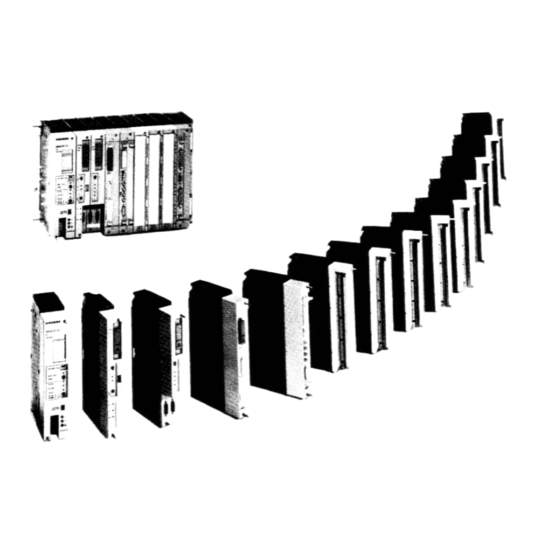
- Page 24 Figures 1-1. S5-115U Components ..........1 - 2 EWA 4NEB 811 6130-02b...
-
Page 25: System Overview
S5-115U Manual System Overview System Overview The SIMATIC® S5-115U programmable controller is used worldwide in almost all fields in a wide range of applications. Each of its modular components handles a specific task. Therefore, you can expand the system according to your needs. Three types of communications systems pass informa- tion among multiple controllers. -
Page 27: Central Processing Units
S5-115U Manual System Overview A lithium battery backs up the program memory and the internal retentive flags, timers and counters in the event of a power failure. An LED signals battery failure. If you change the battery when the power is shut off, connect a back-up voltage from an outside source to the sockets provided for this purpose on the power supply module. -
Page 28: Intelligent Input/Output Modules
System Overview S5-115U Manual The S5-115U offers floating and non-floating analog input modules. They use one range card for every four channels to adapt the desired signal level. This feature allows you to do the following: • have up to four different measuring ranges on one module, depending on the number of channels a module has •... -
Page 29: Centralized Configuration
S5-115U Manual System Overview 1.3.1 Centralized Configuration A centralized configuration allows you to connect up to three EUs to one CC. The interface modules for this purpose connect bus lines and supply voltage to the EUs. The EUs in such configu- rations therefore need no power supplies of their own. -
Page 30: Software
• ergonomic demands increased Siemens has put an end to this trend. SIMATIC provides the following three solutions to keep soft- ware costs down: • the user-friendly STEP 5 programming language with its four methods of representation and convenient structuring capabilities •... - Page 31 Technical Description Modular Design ..........2 - 1 Functional Units .
- Page 32 Figures 2-1. The S5-115U (Central Unit) ......... . . 2 - 1 2-2.
-
Page 33: Technical Description
This chapter describes the design and principle of operation of an S5-115U with accessories. Modular Design The S5-115U consists of various functional units that can be combined to suit the particular pro- blem. SIEMENS Figure 2-1. The S5-115U (Central Unit) The numbered information below briefly describes the most important components of the S5-115U. -
Page 34: Mounting Rack
Technical Description S5-115U Manual Central Processing Unit (CPU) The central processing unit reads in input signal states, processes the control program, and controls outputs. In addition to program scanning functions, the CPU provides internal flags, timers and counters. You can preset the restart procedure and diagnose errors using the CPU's LEDs. -
Page 35: Functional Units
S5-115U Manual Technical Description Not represented: Operating System Submodule (only CPU 944) As well as the PLC operating system, this submodule also contains driver blocks for the second interface. They are loaded into the user memory of the interface after power restore. Intelligent Input/Output Modules (IPs) Intelligent input/output modules are available for handling the special tasks: •... - Page 36 Technical Description S5-115U Manual Program Memory (Internal Program Memory, Memory Submodule) The control program is stored in the memory submodule or in the internal program memory (RAM). The CPU 943 and CPU 944 can hold the entire program in internal RAM. To safeguard against losing the program, dump it in an external EPROM or EEPROM memory sub- module.
- Page 37 S5-115U Manual Technical Description Accumulator (ACCUM) The accumulator is an arithmetic register for loading, for example, internal times and counts. Comparison, arithmetic and conversion operations are also executed in the accumulator. Processor The processor calls statements in the program memory in sequence and executes them in accor- dance with the control program.
-
Page 38: Power Supply Modules
• The RESET switch acknowledges a battery failure indication. Battery compartment Sockets for external 3, 4 to 9 V DC for backup (when SIEMENS battery is changed and power supply is shut off) SIMATIC S5 Battery failure indicator The LED lights up under the following conditions: •... -
Page 39: Central Processing Units
S5-115U Manual Technical Description Central Processing Units Four CPU types are available for the S5-115U. Tables 2-6 and 2-7 show the most important CPU features. Table 2-1. CPU Comparison CPU 941 CPU 942 CPU 943 CPU 944 Execution time per - 1000 statements Approx. - Page 40 Technical Description S5-115U Manual Table 2-1. CPU Comparison (Continued) CPU 941 CPU 942 CPU 943 CPU 944 S5-115U Closed-loop control ASCII driver Point-to-point connection (as master) SINEC L1 Communications link Realtime clock Only at interface SI 2 in the case of CPUs with two serial interfaces ** Only in the case of CPUs with two serial interfaces Table 2-2.
- Page 41 S5-115U Manual Technical Description CPU 941 and CPU 942 The CPU 941 and the CPU 942 both contain a microprocessor and an ap- Internal Operating Memory plication-specific integrated circuit RAM 2 system (ASIC). The microprocessor handles all submodule Kbytes memory programmer interface module...
- Page 42 Technical Description S5-115U Manual CPU 943 The CPU 943 contains an application- specific integrated circuit (ASIC) and a microprocessor. microprocessor Memory Operating handles all programmer interface mo- system memory submodule Internal dule functions, processes interrupts 64 Kbytes for - CPU and substitution operations and con- - 2nd serial in- 48 Kbytes...
- Page 43 S5-115U Manual Technical Description CPU 944 The CPU 944 contains two application- specific integrated circuits (ASICs) and a microprocessor. The microprocessor handles all pro- grammer interface module functions Operating and processes interrupts. The micro- system memory processor also controls the ASIC that 64 Kbytes for - CPU handles...
- Page 44 Technical Description S5-115U Manual Front Panels of the Central Processing Units The following operator functions are possible on the front panel of the CPUs: • Plug in a memory submodule • Connect a programmer (PG) or an operator panel (OP) •...
- Page 45 S5-115U Manual Technical Description The CPU controls are arranged in a panel. Figure 2-8 shows the control panel of the different CPUs. BASP Mode selector STOP/RUN Switch for the following RESTART settings: RUN LED • nonretentive presetting (NR) STOP LED retentive presetting (RE) •...
-
Page 46: Operating Modes
Technical Description S5-115U Manual Operating Modes Use the mode selector to set the "STOP" (ST) or "RUN" (RN) mode. The CPU executes the "RESTART" mode automatically between "STOP" and "RUN". 2.5.1 STOP Mode The program is not scanned in STOP mode. The values of the timers, counters, flags and process images that were current when the CPU went into the STOP state are maintained. - Page 47 S5-115U Manual Technical Description Using this method, the processor determines the bytes of the process I/O image to be updated during process I/O image transfer. Table 2-4 lists all relevant system data words in the system data area. If, for instance, I/O bytes 24 and 25 (=I/O word 24) can be read , bit 4 is set in system data word (SD) 16 ;...
- Page 48 Technical Description S5-115U Manual Programmable Restart Delay at Cold Restart and After Power Restore If you want to delay checking the module configuration because, for example, switching the voltage to a remotely connected EU is delayed, you must modify system data word 126 (EAFC ) in one of the following ways: •...
-
Page 49: Run Mode
S5-115U Manual Technical Description 2.5.3 RUN Mode After the CPU operating system has run the RESTART program, it starts cyclic program scanning (OB1). The input signals at the input modules are scanned cyclically and mapped to the PII; the interpro- cessor communication input flags (see Section 12.1.1) are updated. - Page 50 Technical Description S5-115U Manual Mode selector STOP RUN Power restoration PG command RUN Process I/O image (PII and PIQ) is Process I/O image (PII and PIQ) is deleted ; deleted ; Non-retentive timers, counters and Non-retentive timers, counters and flags are deleted ; flags are deleted ;...
- Page 51 S5-115U Manual Technical Description Cold Restart Characteristics After Power Restoration Battery status, memory submodule and status before POWER OFF are evaluated as follows on cold restart after power restoration: Power ON Battery Is memory sub- in order? module RAM? CPU previously Retentive in STOP feature set?
- Page 52 Technical Description S5-115U Manual Changing the Operating Mode After power restora- STOP tion, if the previous PLC state was STOP. - The mode selec- - The control tor is set from program is STOP to RUN destroyed (e.g. - RUN is selected RAM is erased on a program- after battery...
-
Page 53: Measuring And Estimating The Scan Time And Setting The Scan Monitoring Time
S5-115U Manual Technical Description Measuring and Estimating the Scan Time and Setting the Scan Monitoring Time 2.6.1 Measuring the Scan Time The scan time is measured by the CPU and stored in the system data area. You can access the current, the minimum and the maximum scan time in the control program at any time. -
Page 54: Estimating The Scan Time
Technical Description S5-115U Manual 2.6.2 Estimating the Scan Time The scan time has been divided into various units in the figures below to help you estimate the program runtime and thus the amount of time needed to scan the program. The values shown below are only guidelines, and may differ depending on the configuration of the system involved. - Page 55 S5-115U Manual Technical Description Table 2-5. Subdivision of the User Time User Time T Time required for Time in µsec. CPU 941 CPU 942 Scan cycle control CPU 943 CPU 944 CPU 941 140+ n · (30+module's Ready CPU 942 Reading the PII delay time*) CPU 943...
- Page 56 Technical Description S5-115U Manual The Ready delay time is the time that elapses between the arrival of the Request signal in the module and the module's Ready signal. The delay time depends on • The Ready delay time of the module itself •...
- Page 57 S5-115U Manual Technical Description Figure 2-14 shows the subdivision of the system time. The time values are listed in Table 2-7. PG/OP SINEC L1 Update time cells Figure 2-14. System Time Table 2-7. System Time System Time Time load caused by Approx.
- Page 58 Technical Description S5-115U Manual Response Time Response time is the period between the input signal change and the output signal change. This time is typically the sum of the following elements (see also Figure 2-15): • the inherent delay of the input module •...
-
Page 59: Setting The Scan Monitoring Time
S5-115U Manual Technical Description 2.6.3 Setting the Scan Monitoring Time The scan time comprises the duration of the cyclic program. At the beginning of each program scan, the processor starts a monitoring time (cycle trigger). This monitoring time is preset to approximately 500 ms. -
Page 60: Backup Battery
Technical Description S5-115U Manual 2.7.1 Backup Battery The backup battery maintains the program and data when the S5-115U is switched off. The backup battery has a service life of approximately two years. After a lengthy storage period lithium batteries develop a passivation coating which is respon- sible for the "voltage delay effect"... -
Page 61: Programmers (Pg)
S5-115U Manual Technical Description 2.7.3 Programmers (PG) Applications: • entering programs • testing programs • monitoring programs. You can use the following programmers: PG 605U, PG 635, PG 670, PG 675, PG 685, PG 695, PG 710, PG 730, PG 750 and PG 770. You can use the programmers in either on-line or off-line mode on. - Page 62 EWA 4NEB 811 6130-02b...
-
Page 63: Installation Guidelines
Installation Guidelines Mounting Rack ..........3 - 1 3.1.1 Central Controller (CC) . - Page 64 EWA 4NEB 811 6130-02b...
- Page 65 Figures 3-1. Central Controller (Example) ......... 3 - 1 3-2.
- Page 66 Figures 3-35. Laying Equipotential Bonding Conductor and Signal Cable ....3 - 44 3-36. Fixing Shielded Cables with Various Types of Cable Clamps ....3 - 46 3-37.
- Page 68 Installation Guidelines S5-115U Manual The following five mounting racks (CRs) are available for installing a central controller: • CR 700-0LA12 and CR 700-0LB11: for central controller 0 • CR 700-1: for central controller 1 • CR 700-2: for central controller 2 •...
- Page 69 S5-115U Manual Installation Guidelines Possible Configurations on Mounting Rack CR 700-0 (6ES5 700-0LB11) You can use adapter casings with two printed-circuit boards in the case of the CR 700-0 (6ES5 700-0BL11) in contrast to the CR 700-0 (6ES5 700-0LA12). There are also slots for a power supply module (PS), a central processing unit (CPU), block type digital/analog modules, intelligent input/output modules and communications processors (CPs).
- Page 70 Installation Guidelines S5-115U Manual Possible Configurations on Mounting Rack CR 700-1 Use central mounting rack CR 700-1 to install small or medium-sized control systems. It has slots for a power supply module (PS), a central processing unit (CPU), and up to seven input/output modules (I/Os).
- Page 71 S5-115U Manual Installation Guidelines Possible Configurations on Mounting Rack CR 700-2 Use central mounting rack CR 700-2 to install large control systems in 19-inch cabinets. It has slots for a power supply module (PS), a central processing unit (CPU) and input/output modules. Such a configuration makes up a central controller 2.
-
Page 72: Mounting Rack
Installation Guidelines S5-115U Manual Possible Configurations on Mounting Rack CR 700-2LB Use central mounting rack CR 700-2LB to install large control systems in 19-inch cabinets. In contrast to the central mounting racks CR 700-0/1 you can use adapter casings with two printed circuit boards here. - Page 73 S5-115U Manual Installation Guidelines Possible Configurations on Mounting Rack CR 700-3 Use central mounting rack CR 700-3 to install large control systems in 19-inch cabinets. In contrast to the central mounting racks CR 700-0/1/2, you can also use printed circuit boards in an adapter casing here.
-
Page 75: Central Controller (Cc)
S5-115U Manual Installation Guidelines Possible Configurations on Mounting Rack ER 701-0 Use expansion mounting rack ER 701-0 to install expansion unit EU 0. EU 0 is suitable for centra- lized configurations, i.e. connection to a local central controller of type CC 0, CC 1 or CC 2. The ER 701-0 has six slots for digital and analog input or output modules and one slot for an IM 305 or IM 306 interface module. - Page 76 Installation Guidelines S5-115U Manual Possible Configurations on Mounting Rack ER 701-1 Use expansion mounting rack ER 701-1 to install expansion unit EU 1. EU 1 is suitable for centralized configurations, i.e., connection to a local central controller of type CC 0, CC 1, CC 2 or CC 3.
- Page 77 S5-115U Manual Installation Guidelines Possible Configurations on Mounting Rack ER 701-2 Use expansion mounting rack ER 701-2 to install expansion unit EU 2. EU 2 is suitable for connection to a centrally configured or remote CC 2/CC 3 central controller. The ER 701-2 has slots for a power supply module (PS), digital and analog input or output modules, one central controller interface module, and one IM 306 expansion unit interface module.
- Page 78 Installation Guidelines S5-115U Manual Possible Configurations on Mounting Rack ER 701-3 Use expansion mounting rack ER 701-3 to install expansion unit EU 3. EU 3 is suitable for con- nection to a centrally configured or remote CC 2/CC 3 central controller. ER 701-3 has slots for a power supply module (PS), digital and analog input or output modules, communications processors and intelligent input/output modules (interrupt-triggering modules can only be used via an IM 307/317), one central controller interface module, and one IM 306 expansion unit...
-
Page 85: Centralized Configurations
S5-115U Manual Installation Guidelines 3.2.5 Centralized Configurations A central controller (CC 0, CC 1, CC 2 or CC 3) connected via short connecting cables to as many as three expansion units makes up a centralized configuration. Use only the IM 305 or IM 306 interface modules to connect an ER 701-1 mounting rack. -
Page 86: Distributed Configuration
Installation Guidelines S5-115U Manual 3.2.6 Distributed Configuration A central controller connected to expansion units installed over a maximum distance of 3000 m (9800 ft.) makes up a distributed configuration. The interface module used determines the distance and the number of EUs that can be connected. Distributed configurations using the following are not described here: •... - Page 87 S5-115U Manual Installation Guidelines Table 3-3. Technical Specifications of the Interface Modules for Distributed Configurations Number of Total Cable Length Power Consumption Expansion Units (Max.) at 5 V (Max.) AS 301 0.8 A 200 m AS 310 0.7 A AS 302 2.0 A 1000 m AS 311...
- Page 88 Installation Guidelines S5-115U Manual Connection with IM 304/IM 314 Interface Modules Plug the IM 304 interface module into a CR 700-2/-3-0LB central rack to connect as many as four EUs per interface to the CC. Plug an IM 314 into each ER 701-2 or ER 701-3 expansion rack. Connect the interface modules with the 6ES5 721-..
- Page 89 S5-115U Manual Installation Guidelines The following is a description of the switch and jumper settings for the IM 304-3UA1. and for the IM 304-3UB1. Switch and Jumper Settings on the IM 304-3UA1. for Distributed Connection Figure 3-21 shows the position of the switches and jumpers on the IM 304 module. If you use the IM 304 interface module for distributed configuration, please set the jumpers as shown on jumper block X11.
- Page 90 Installation Guidelines S5-115U Manual • Set the jumpers on X12 to adapt the cable length for distributed connection. When you set the jumpers on X12, use the longest link connected to interface X3 or X4 to determine the setting. If you use IPs and CPs on the EU, you must set the longest total length, regardless of the length of the connection line.
- Page 91 S5-115U Manual Installation Guidelines Switch and Jumper Settings on the IM 304-3UB1. for Distributed Connection Figure 3-22 shows the positions of the switches and jumpers on the IM 304-3UB1. module. All switches on switch block S3 must be in the ON position. IM 304-3UB1.
- Page 92 Installation Guidelines S5-115U Manual • Use jumper X11 to set the total length of the 721 connecting cables of one interface up to the last EU. The decisive factor for setting jumper X11 is the interface with the longest connection line.
- Page 93 S5-115U Manual Installation Guidelines Switch and Jumper Settings on the IM 314 Interface Module for Distributed Connection Jumpers BR1 to BR3 must be set as follows depending on the EU used: Using the IM 314 in the ER 701-2. ER 701-3 (S5-115U) Using the IM 314 in the EU 183U Using the IM 314 in the EU 185U and EU 186U Figure 3-23.
-
Page 94: Other Possible Configurations
Installation Guidelines S5-115U Manual 3.2.7 Other Possible Configurations Central controllers and expansion units of the S5-115U system can also be connected to CCs and EUs of other SIMATIC S5 systems. Table 3-4 shows the possible configurations. Table 3-4. Connection of the S5-115U System to other SIMATIC S5 Systems Configuration Central Central Controller... -
Page 95: Wiring
S5-115U Manual Installation Guidelines Wiring The backplane on the mounting rack establishes the electrical connection between all modules. Make the following additional wiring connections: • The PS 951 power supply module to the power line • The sensors and actuators to the digital or analog modules. Connect the sensors and actuators to a front connector that plugs into the contact pins on the front of each module. -
Page 96: Connecting Digital Modules
Installation Guidelines S5-115U Manual 3.3.2 Connecting Digital Modules Digital modules are available in nonfloating and floating versions. For the nonfloating modules, the reference voltage of the external process signals (M ) has to be connected to the internal reference voltage (M , i.e., PE) (see Figure 3-25). - Page 100 The Load Circuit: For monitoring reasons, you should use the same power supply for control and load circuits. For the 24 V DC power supply, a Siemens load power supply unit of the 6EV13 series is recommended (see Catalog ET1).
-
Page 101: Electrical Installation With Field Devices
S5-115U Manual Installation Guidelines 3.4.2 Electrical Installation with Field Devices The following figures each show an example circuit for connecting control power supply and load power supply. They also show the grounding concept for operation from the following: • Grounded supplies •... - Page 102 Installation Guidelines S5-115U Manual Load power supply • For 24 V DC load circuits, you require a load power supply unit with safe electrical isolation. • You require a back-up capacitor (rating: 200µF per 1 A load current) for nonstabilized load power supply units.
- Page 103 S5-115U Manual Installation Guidelines Operating a programmable controller with field devices on grounded supply Operation from grounded power supplies offers the best protection against interference. Low voltage distribution e.g. TN-S system Cabinet Programmable controller Control power supply L+/L1 µ U int L-/N Floating Floating...
- Page 104 Installation Guidelines S5-115U Manual Operating a programmable controller with field devices on a centrally grounded supply In plants with their own transformers or generators, the PLC is connected to the central grounding point. A removable connection must be provided for measuring ground faults. Installation of the PLC must be such that there is insulation between the cabinet potential and the protective conductor potential.
- Page 105 S5-115U Manual Installation Guidelines Operating a Programmable Controller with Field Devices on Non-grounded Supply Neither the outer conductor nor the neutral are connected to the protective conductor in the case of nongrounded supplies. Operation of the PLC with nonfloating power supply modules is not permissible.
-
Page 106: Connecting Nonfloating And Floating Modules
Installation Guidelines S5-115U Manual 3.4.3 Connecting Nonfloating and Floating Modules The following sections show the special features involved in installations with nonfloating and floating modules. Installation with nonfloating modules In installations with nonfloating modules, the reference potential of the control circuit (M internal and the load circuits (M ) are galvanically isolated. - Page 107 S5-115U Manual Installation Guidelines Note It is imperative that you connect the reference potential of the load power supply unit with the L-terminal of the module in the case of 24 V DC DQ modules. If this connection is missing (e.g. wirebreak), a current of typically 15 mA can flow at the outputs.
-
Page 108: Wiring Arrangement, Shielding And Measures Against Electromagnetic Interference
Installation Guidelines S5-115U Manual Wiring Arrangement, Shielding and Measures against Electromagnetic Interference This section describes the wiring arrangements for bus cables, signal cables, and power supply cables that guarantee the electromagnetic compatibility (EMC) of your installation. 3.5.1 Running Cables Inside and Outside a Cabinet Dividing the lines into the following groups and running the groups separately will help you to achieve electromagnetic compatibility (EMC). -
Page 109: Running Cables Outside Buildings
Install these protective elements at the point where the cable enters the building. Note Lightning protection measures always require an individual assessment of the entire system. If you have any questions, please consult your local Siemens office or any company specializing in lightning protection. Grounding Make certain that you have sufficient equipotential bonding between the devices. - Page 110 Installation Guidelines S5-115U Manual 3.5.3 Equipotential Bonding Potential differences may occur between separate sections of the system if • Programmable controllers and I/Os are connected via non-floating interface modules or • Cables are shielded at both ends but grounded via different sections of the system. Potential differences may be caused, for instance, by differences in the system input voltage.
-
Page 111: Shielding Cables
S5-115U Manual Installation Guidelines 3.5.4 Shielding Cables Shielding is a measure to weaken (attenuate) magnetic, electric or electromagnetic interference fields. Interference currents on cable shields are discharged to ground over the shield bar which has a conductive connection to the housing. So that these interference currents do not become a source of interference in themselves, a low-resistance connection to the protective conductor is of special importance. -
Page 112: Special Measures For Interference-Free Operation
Installation Guidelines S5-115U Manual Note the following when connecting the cable shield: • Use metal cable clamps for fixing the braided shield. The clamps have to enclose the shield over a large area and make good contact (see Figure 3-36). •... - Page 113 S5-115U Manual Installation Guidelines Mains Connection for Programmers Provide a power connection for the programmer in each cabinet. The plug must be supplied from the distribution line to which the protective ground for the cabinet is connected. Cabinet Lighting Use, for example, LINESTRA® lamps for cabinet lighting. Avoid the use of fluorescent lamps since these generate interference fields.
- Page 114 EWA 4NEB 811 6130-02b...
-
Page 115: Plc System Start-Up And Program Test
PLC System Start-Up and Program Test Prerequisites for Starting Up a PLC ......4 - 1 Steps for System Start-Up . - Page 116 Figures 4-1. Relevant Bits for Setting the Retentive Feature in System Data Word 120 ..........4 - 6 4-2.
-
Page 117: Plc System Start-Up And Program Test
S5-115U Manual PLC System Start-Up and Program Test PLC System Start-Up and Program Test This chapter contains notes on starting up an S5-115U with information on testing your STEP 5 control program. A prerequisite is knowledge of the principle of operation of the PLC (see Chapter 2). There are notes on starting up a system at the end of the chapter. - Page 118 PLC System Start-Up and Program Test S5-115U Manual There are two ways of deleting the internal program memory: • Offline via the switch for "Default/Overall Reset" • Online with the "Delete" programmer function. Overall Reset via the Switch for "Default/Overall Reset" on the Control Panel of the CPU Switch on the power supply module Set the CPU mode selector to STOP (ST) Set the switch for "Default/Overall Reset"...
-
Page 119: Transferring The Program
S5-115U Manual PLC System Start-Up and Program Test 4.2.2 Transferring the Program There are two ways of entering the control program in the CPU: • Transfer the program to a memory submodule and insert the submodule into the receptacle of the CPU. CPUs 941 and 942 process the control program direct from the submodule. - Page 120 PLC System Start-Up and Program Test S5-115U Manual Transferring the program directly to the CPU internal program memory If you transfer the control program directly to the CPU program memory, you must link the programmer and CPU via a suitable connecting cable (in the case of the CPU 943 and CPU 944 both interface SI 1 and interface SI 2 are suitable for connecting the programmer;...
-
Page 121: Determining The Retentive Feature Of Timers, Counters And Flags
S5-115U Manual PLC System Start-Up and Program Test Special Points When Setting Up Data Blocks • Data blocks generated in the control program with the "G DB" operation are automatically dumped by the operating system direct in internal program memory. The contents of the data blocks can be changed using STEP 5 operations. - Page 122 PLC System Start-Up and Program Test S5-115U Manual The retentive feature in the RE switch position is determined by an entry in system data word 120 (EAF0 SD 120 0: FY 0 to FY 127 retentive and FY 128 to FY 255 nonretentive 1: All flags retentive 0: T 0 to T 63 retentive and T 64 to T 127 nonretentive...
-
Page 123: Testing The Program
S5-115U Manual PLC System Start-Up and Program Test Testing the Program The following describes the steps for starting the control program in the S5-115U. This is followed by the description of the test functions with which you can locate logical errors in program processing. -
Page 124: Search
PLC System Start-Up and Program Test S5-115U Manual 4.3.2 Search The "Search" function is used to find operands or symbols in the STEP 5 program. This function makes it easier to handle longer control programs. The search function is executed differently in the individual programmers and is described in detail in the relevant manual. -
Page 125: Status/Status Var Test Function
S5-115U Manual PLC System Start-Up and Program Test 4.3.4 STATUS/STATUS VAR Test Function The STATUS and STATUS VAR test functions indicate signal states of operands and the RLO. Depending on when the signal states are observed, a distinction is made between program- dependent signal status display (STATUS) and direct signal status display (STATUS VAR). - Page 126 PLC System Start-Up and Program Test S5-115U Manual Outputting Signal States on a Display Screen The display of signal states on a screen differs according to the following methods of represen- tation: STL: Signal states are represented as a listing of information. CSF/LAD: Signal states are represented by different types of connecting lines as shown in Figure 4-3: Signal state 1...
-
Page 127: Force Outputs And Variables
S5-115U Manual PLC System Start-Up and Program Test Direct Signal Status Display "STATUS VAR" Use the "STATUS VAR" test function to indicate the state of a random operand (input, output, flag, data word, counter, or timer) at the end of a program scan. The information is taken from the process image of the operands in question. -
Page 128: Special Features Of The Cpus With Two Serial Interfaces
PLC System Start-Up and Program Test S5-115U Manual Special Features of the CPUs with Two Serial Interfaces CPU 943 and CPU 944 are also available with two serial interfaces. You can connect programmers and operator panels to both interfaces. Table 4-2 shows the range of functions of the interfaces. Connection of a programmer, operator panel or SINEC L1 at SI 1 or SI 2 can cause an increase in the program execution time. -
Page 129: Notes On The Use Of Input/Output Modules
S5-115U Manual PLC System Start-Up and Program Test Further Functions at Interface SI 2 • Point-to-point connection (master function) • ASCII driver • Integral clock • Computer link with 3964(R) procedure (only in the case of CPU 944 with the relevant oper- ating system submodule for the purpose). -
Page 130: System Start-Up
PLC System Start-Up and Program Test S5-115U Manual System Start-Up The following section contains: • Notes on configuring a system with important regulations which must be observed in order to avoid hazardous situations. • The description of the system startup procedure. 4.6.1 Suggestions for Configuring and Installing the Product A programmable controller is often used as a component in a larger system. -
Page 131: System Start-Up Procedure
S5-115U Manual PLC System Start-Up and Program Test • Activation of the EMERGENCY STOP facility must create a hazard-free state for personnel and plant: - Actuators and drives which could cause hazardous states (e.g. main spindle drives for ma- chine tools) must be switched off. - On the other hand, actuators and drives which could constitute a hazard to personnel or plant when switched off (e.g. - Page 132 PLC System Start-Up and Program Test S5-115U Manual Step 3: Testing the signal inputs (peripheral) - Insert the fuse for the signal sensors. Leave the fuses for the actuators and the power circuits disconnected. - Activate all sensors in sequence. - You can scan all inputs using the "STATUS VAR"...
-
Page 133: Error Diagnostics
Error Diagnostics Interrupt Analysis ..........5 - 2 5.1.1 "ISTACK"... - Page 134 Figures 5-1. Structured Program with Illegal Statement ......5 - 12 5-2. Addresses in the CPU Program Memory ....... 5 - 13 5-3.
-
Page 135: Error Diagnostics
S5-115U Manual Error Diagnostics Error Diagnostics Malfunctions in the S5-115U can have various causes. If the PLC malfunctions, first determine whether the problem is in the CPU, the program, or the I/O modules (see Table 5-1). Table 5-1. General Error Analysis Fault/Error Condition Fault/Error Analysis The CPU is in the "STOP"... -
Page 136: Interrupt Analysis
Error Diagnostics S5-115U Manual Interrupt Analysis When malfunctions occur, the operating system sets various "analysis bits" that can be scanned with the programmer using the "ISTACK" function. LEDs on the CPU also report some malfunc- tions. 5.1.1 "ISTACK" Analysis The interrupt stack (ISTACK) is an internal memory of the CPU where malfunction reports are stored. - Page 137 S5-115U Manual Error Diagnostics ISTACK display on the PG 605U The following table shows which bits in the ISTACK are relevant for error diagnostics. The bits in boxes with heavy borders indicate the cause of a malfunction and the step address counter. Table 5-2.
- Page 138 Error Diagnostics S5-115U Manual Table 5-2. ISTACK Display on PG 605U (Continued) Abso- System lute data word Byte addr. (SD) 2nd nesting level EBA4 SD 210 3rd nesting level EBA5 Nesting depth (0 to 6) EBA2 SD 209 1st nesting level EBA3 Start address of the data block (high) EBA0...
- Page 139 S5-115U Manual Error Diagnostics ISTACK Display on the PG 635/670/675/685/695 and 750 Tables 5-3 and 5-4 show the ISTACK as it is displayed on CRT-based programmers. Relevant information for the S5-115U is in bold print. Table 5-3. Control Bit Display Absolute System CONTROL BITS...
-
Page 140: Meaning Of The Istack Displays
Error Diagnostics S5-115U Manual 5.1.2 Meaning of the ISTACK Displays Use Table 5-5 to determine the cause of a fault or an error when program scanning is interrupted. In each case, the CPU goes into the "STOP" mode. Table 5-5. Meaning of the ISTACK Displays Fault/Error Cause Fault/Error... - Page 141 S5-115U Manual Error Diagnostics Table 5-5. Meaning of ISTACK Displays (Continued) Fault/Error Cause Error/Fault Cause Remedy (ID in ISTACK) Substitution error: Correct the function block call. Program A function block was called with an scanning incorrect actual parameter. interrupted Transfer error: Correct the program error.
- Page 142 Error Diagnostics S5-115U Manual Table 5-6. Mnemonics for Control Bits and Interrupt Display Control Bit Mnemonics Mnemonics for Cause of Error/Fault (=Error ID) BSTSCH Block shift requested STOPS Interrupt display word Substitution error SCHTAE Block shift active (function: TRAF Transfer error for data block statements: KOMP:AG) data word number >data block length.
-
Page 143: Led Error Signalling
S5-115U Manual Error Diagnostics 5.1.3 LED Error Signalling Certain errors are indicated by LEDs on the CPU depending on its design. Table 5-7 explains these error signals. Table 5-7. Meaning of the Error LEDs on the CPUs Meaning Timeout (CPU went into STOP mode) lights up Scan time exceeded (CPU went into STOP mode) lights up... -
Page 144: Error Messages When Using Memory Submodules
Error Diagnostics S5-115U Manual 5.1.4 Error Messages When Using Memory Submodules (only in the case of CPU 943/944) A flashing red LED (STOP LED) indicates errors when memory submodule blocks are loaded into the internal RAM. The cause of error is stored in system data word 102. Table 5-8. -
Page 145: Program Errors
S5-115U Manual Error Diagnostics Program Errors Table 5-9 lists malfunctions caused by program errors. Table 5-9. Program Errors Error Action All inputs are zero Check the program All outputs are not set One input is zero. One output is not set Check program assignments (double assignment, edge formation) Timer or counter is not running or is incorrect... -
Page 146: Determining An Error Address
Error Diagnostics S5-115U Manual 5.2.1 Determining an Error Address The STEP address counter (SAZ) in the ISTACK (bytes 25 and 26) indicates the absolute memory address of the STEP 5 statement in the PLC before which the CPU went into the "STOP" mode. You can use the "DIR PC"... - Page 147 S5-115U Manual Error Diagnostics Absolute addresses in B000 the internal RAM OB1 header B009 B00A JU PB 0 B00B B00C B00D B00E PB0 header It is impossible to locate a program error B017 from the physical address of the illegal B018 statement in the RAM.
- Page 148 Error Diagnostics S5-115U Manual Address Calculation (necessary only when using the PG 605U programmer) To make program corrections, you need the address of the statement that caused the malfunc- tion, relative to the particular block (relative address). Determine the faulty block by comparing the STEP address counter value (SAZ value) and the "DIR PC"...
-
Page 149: Program Trace With The Block Stack ("Bstack") Function
S5-115U Manual Error Diagnostics 5.2.2 Program Trace with the Block Stack ("BSTACK") Function (not possible on the PG 605U programmer) During program scanning, jump operations enter the following information in the block stack: • the data block that was valid before program scanning exited a block; •... -
Page 150: Other Causes Of Malfunction
Error Diagnostics S5-115U Manual Other Causes of Malfunction Hardware components or improper installation can also cause malfunctions. Table 5-10 summa- rizes such malfunctions. Table 5-10. Other Causes of Malfunction Fault/Error Action All inputs are zero. Check the module and the load voltage. All outputs are not set. -
Page 151: Addressing/Address Assignments
Addressing/Address Assignments Address Structure ..........6 - 1 6.1.1 Digital Module Addresses... - Page 152 Figures 6-1. Format of a Digital Address ......... . 6 - 1 6-2.
-
Page 153: Addressing/Address Assignments
S5-115U Manual Addressing/Address Assignments Addressing/Address Assignments In order to be able to access input/output modules, these modules must be assigned addresses. Address Structure Digital modules generally are addressed by bit, analog modules by byte or word. Consequently, their addresses have different formats. 6.1.1 Digital Module Addresses One bit represents a channel on a digital module. -
Page 154: Fixed Slot Address Assignments
Addressing/Address Assignments S5-115U Manual 6.2.1 Fixed Slot Address Assignments Input/output modules are referenced under permanently assigned slot addresses when the following conditions exist for the S5-115U: • The PLC is operated without an expansion unit interface module and a terminating resistor is used. -
Page 155: Variable Slot Address Assignments
S5-115U Manual Addressing/Address Assignments Slot numbers in the expansion unit 28.0 32.0 36.0 40.0 44.0 48.0 52.0 56.0 60.0 Digital modules 31.7 35.7 39.7 43.7 47.7 51.7 55.7 59.7 63.7 Analog modules Analog cannot be plugged modules in here. Modules Addresses Figure 6-3. - Page 156 Addressing/Address Assignments S5-115U Manual Addresses Address switches (ON=1, OFF=0) SLOT ADDRESS BIT for digital 7 6 5 4 3 2 1 modules Addresses Address switches for analog modules : Slot number : Address switches : Switch for setting the number of inputs or : DIP switch outputs per slot Figure 6-4.
- Page 157 S5-115U Manual Addressing/Address Assignments Setting Addresses Use the left-hand switch ( in Figure 6-4) on the addressing panel of the IM 306 to indicate what type of module you have plugged into the slot. Proceed as follows: Set the switch to OFF: for a 32-channel digital module or a 16-channel analog module. Set the switch to ON: for a 16-channel digital module or an 8-channel analog module.
- Page 158 Addressing/Address Assignments S5-115U Manual The module is then addressed as follows: Channel No. 2 . . . 10 . . . Address 46.0 46.1 46.7 47.0 47.1 47.7 EWA 4NEB 811 6130-02b...
-
Page 159: Handling Process Signals
S5-115U Manual Addressing/Address Assignments Handling Process Signals Input/output module signal states can be read from or written to the addresses shown in Figure 6-6. F000 Digital modules F07F F080 Analog modules F0FF Absolute address Relative byte addresses Figure 6-6. Addresses of the Input/Output Modules Digital module signal states are also stored in a special memory area called the process image. -
Page 160: Accessing The Pii
Addressing/Address Assignments S5-115U Manual 6.3.1 Accessing the PII At the beginning of program scanning, the input module signal states are written to the PII. The statements in the control program use a particular address to indicate what information is currently needed. The control logic then reads the data that was current at the beginning of pro- gram scanning and works with it. -
Page 161: Accessing The Piq
S5-115U Manual Addressing/Address Assignments 6.3.2 Accessing the PIQ New signal states are entered in the PIQ during program scanning. This information is transferred to the output modules at the end of each program scan. Writing bit by bit Bit No. in binary operations: 7 6 5 4 3 2 1 0 =Q 4.6... -
Page 162: Direct Access
Addressing/Address Assignments S5-115U Manual 6.3.3 Direct Access Analog module signal states are not written to the process image. They are read in or transferred to an output module directly with the "L PB/PY x", "L PW x", "T PB/PY x", or "T PW x" statements. You can also exchange information with digital modules directly. -
Page 163: Address Allocation On The Central Processing Units
S5-115U Manual Addressing/Address Assignments Note On the CPU 944, the digital inputs can be read with OB254 and the PIQ output to the output modules with OB255, irrespective of the contents of system data word SD 120 (also see Chapter 11, "Integral Blocks"). Address Allocation on the Central Processing Units The following figures show the contents of CPU RAM. - Page 164 Addressing/Address Assignments S5-115U Manual Address Kbytes Address Kbytes 0000 0000 "Intelligent" I/Os "Intelligent" I/Os 1000 1000 Memory submodule 5000 5000 8 K statements 16 K st. Memory submodule 7000 8 K st. 7000 4 K st. 4 K st. 9000 9000 Internal user memory (1 K st.) Internal user memory (5 K st.)
- Page 165 S5-115U Manual Addressing/Address Assignments Address Kbytes 0000 "Intelligent" I/Os 1000 E(E)PROM Internal submodule user memory (max. 24 K (RAM) 24 K statements statements useful/ copied to internal RAM) D000 (Internal data) DC00 Block address list E600 57,50 (Internal data) EA00 58,50 System data SD EC00...
- Page 166 Addressing/Address Assignments S5-115U Manual Address Address Kbytes 0000 "Intelligent" I/Os 1000 1001 Internal Internal E(E)PROM user memory user memory submodule (RAM) 24 K statements (RAM) 24 K statements (max. 48 K statements BANK 1 BANK 2 useful/ For program only copied to internal RAM) (OBs, FBs, SBs, PBs)
- Page 167 S5-115U Manual Addressing/Address Assignments The input/output area is subdivided as follows: Address Kbytes F000 I/O modules (P area) F100 Q area 60.25 F200 Interprocessor communication flags 60.50 F300 60.75 F400 Page frame F800 FC00 IM 3-area 63.00 FD00 IM 4-area 63.25 Interface registers for CPs and IPs FEFF...
- Page 168 Addressing/Address Assignments S5-115U Manual The following table lists the system data of relevance to the user and indicates the sections which provide more detailed information. Table 6-1. Address Allocation in the System Data Area System Data Address Details in Description On CPU Word (hex.)
- Page 169 S5-115U Manual Addressing/Address Assignments Table 6-1. Address Allocation in the System Data Area (Continued) System Data Address Details in Description On CPU Word (hex.) Section EAC4 Interval timer for OB12 941,942, 7.4.3 EAC5 (multiple of 10 ms) 943,944 EAC6 Interval timer for OB11 941,942, 7.4.3 EAC7...
- Page 170 Addressing/Address Assignments S5-115U Manual Table 6-2. Address Allocation in the Flag, Timer and Counter Areas Details Abs. Address Memory Area in Section (hex.) FY 0 EE00 Flags (F) FY 1 8.1.2 EE01 FY 255 EEFF EC00, EC01 Timers (T) 8.1.4 EC02, EC03 T 127 ECFE, ECFF...
-
Page 171: Introduction To Step 5
Introduction to STEP 5 Writing a Program ......... . . 7 - 1 7.1.1 Methods of Representation... - Page 172 Figures 7-1. Compatibility of STEP 5 Methods of Representation ....7 - 2 7-2. Nesting ............7 - 6 7-3.
-
Page 173: Writing A Program
S5-115U Manual Introduction to STEP 5 Introduction to STEP 5 This chapter explains how to program the S5-115U. It describes how to write a program, how the program is structured, the types of blocks the program uses, and the number representation of the STEP 5 programming language. - Page 174 Introduction to STEP 5 S5-115U Manual Each method of representation has its special characteristics. Therefore, a program block that has been programmed in STL cannot necessarily be output in CSF or LAD form. The graphic represen- tations are not compatible to each other either. However, programs in CSF or LAD can always be converted to STL.
-
Page 175: Operand Areas
S5-115U Manual Introduction to STEP 5 7.1.2 Operand Areas The STEP 5 programming language has the following operand areas: (inputs) interfaces from the process to the PLC (outputs) interfaces from the PLC to the process (flags) memory for intermediate results of binary operations (data) memory for intermediate results of digital operations (timers) -
Page 176: Program Structure
Introduction to STEP 5 S5-115U Manual Example: Hard-Wired Control A signal lamp is supposed to light up when a normally open contact (S1) is activated and a normally closed contact (S2) is not activated. Programmable Control The signal lamp is connected to a PLC output (Q 2.0). The signal voltages of the two contacts are connected to two PLC inputs (I 1.1 and I 1.2). -
Page 177: Structured Programming
S5-115U Manual Introduction to STEP 5 7.2.2 Structured Programming To solve complex tasks, it is advisable to divide an entire program into individual, self-contained program parts (blocks). This procedure has the following advantages: This procedure has the following advantages: • simple and clear programming, even for large programs •... - Page 178 Introduction to STEP 5 S5-115U Manual The program uses block calls to exit one block and jump to another. You can therefore nest program, function, and sequence blocks randomly in up to 32 levels (see Section 7.3). Note When calculating the nesting depth, note that the system program itself can call an organization block under certain circumstances (e.g.
-
Page 179: Block Types
S5-115U Manual Introduction to STEP 5 Block Types Table 7-2 lists the most important features of the block types. Table 7-2. Comparison of Block Types Quantity OB 0 to OB 255 PB 0 to PB 255 SB 0 to SB 255 FB 0 to FB 255 DB 2 to DB 255 Maximum... -
Page 180: Organization Blocks (Obs)
Introduction to STEP 5 S5-115U Manual Block Structure Each block consists of the following: • Block header specifying the block type, number, and length. The programmer generates the block header when it transforms the block. • Block body with the STEP 5 program or data. Synchronization Absolute pattern... - Page 181 S5-115U Manual Introduction to STEP 5 Table 7-3. Overview of Organization Blocks OB No. Function OB integrated in CPU OB must be user-programmed and be called by the operating system Cyclic program scanning OBs for interrupt-driven and time-controlled program scanning Interrupt A: Digital input module -434 and IP generate interrupt...
- Page 182 Introduction to STEP 5 S5-115U Manual Figure 7-4 shows how to set up a structured control program. It also illustrates the significance of organization blocks. OB21/OB22 FB200 System program Control program Figure 7-4. Example of Organization Block Use 7-10 EWA 4NEB 811 6130-02b...
-
Page 183: Program Blocks (Pbs)
S5-115U Manual Introduction to STEP 5 7.3.2 Program Blocks (PBs) Self-contained program parts are usually programmed in blocks. Special feature: Control functions can be represented graphically in program blocks. Call Block calls JU and JC activate program blocks. You can program these operations in all block types except data blocks. - Page 184 Introduction to STEP 5 S5-115U Manual Block Header In contrast to other types of blocks, function blocks have other organization information in addition to the block header. Its memory requirements consist of the following: • block description as for other blocks (five words) •...
- Page 185 S5-115U Manual Introduction to STEP 5 The name, type of parameter and type of data must be entered when setting parameters. Block header Name NAME: EXAMPLE DECL: IN1 Block parameter DECL: IN2 Name Block parameter DECL: OUT1 Q BI Type of data Type of parameter : A = IN1 : A = IN2...
- Page 186 Introduction to STEP 5 S5-115U Manual Table 7-4. Block Parameter Types and Data Types with Permissible Actual Operands Parameter Data Type Permissible Actual Operands Type I, Q for an operand with bit address x.y inputs x.y outputs x.y flags for an operand with byte address input bytes QB x output bytes...
- Page 187 S5-115U Manual Introduction to STEP 5 A function block call consists of: • Call statement - JU Absolute call of the FB x ( J ump A bsolute...) Call if RLO=1 ( J ump C onditional...) - JC • Parameter list (only necessary if block parameters have been defined in the FB) Function blocks can only be called if they have already been programmed.
-
Page 188: Data Blocks (Dbs)
Introduction to STEP 5 S5-115U Manual Executed program ... NAME: EXAMPLE DECL : X1 I DECL : X2 I at first call DECL : X3 Q BI : JU NAME : EXAMPLE F 1.3 Q 0.1 I 4.1 Parameter list for F 1.3 : BE first call... - Page 189 S5-115U Manual Introduction to STEP 5 Programming Data Blocks Begin data block programming by specifying a block number between 2 and 255. DB0 is reserved (for the operating system) and DB1 is reserved (for initializing internal functions (see Chapter 11) and for defining interprocessor communication flags (see Chapter 12)).
-
Page 190: Program Execution
Introduction to STEP 5 S5-115U Manual Program Execution Some organization blocks handle the task of structuring and managing the control program. These OBs can be grouped as follows according to task: • OBs for RESTART program execution • OB for cyclic program execution •... - Page 191 S5-115U Manual Introduction to STEP 5 OB22 STL Explanation Output words 0, 2, and 4 are set to "0". The information in input words 6, 8, and 10 is loaded into ACCUM 1 consecutively. If an input/output module cannot be accessed with the statement L PW or T PW, the CPU jumps to the STOP mode at this statement and the interrupt bit QVZ (timeout) is set in the ISTACK (see Section 5.1).
-
Page 192: Cyclic Program Execution
Introduction to STEP 5 S5-115U Manual FB1 STL Explanation NAME :CLEAR F FW 200 is preset with "0". "0" is stored in ACCUM 1. The contents of FW 200 indicate the address of the current flag word. The current flag word is set to "0". The contents of FW 200 are incremented by 2. -
Page 193: Integral Function Blocks
S5-115U Manual Introduction to STEP 5 Timed-interrupt OBs interrupt the cyclic program after every STEP 5 operation. Timed-interrupt OBs cannot interrupt the following: • Integral function blocks • • Process interrupts (OB2 to 5). Timed-interrupt OBs themselves can be interrupted by OB6 or by process interrupts (OB2 to 5)! Please note that the call intervals may vary as a result. -
Page 194: Interrupt-Driven Programming Execution
Introduction to STEP 5 S5-115U Manual 7.4.4 Interrupt-Driven Programming Execution OBs 2 to 5 are called automatically by the operating system when a (process) interrupt (interrupt A, B, C or D) occurs. See Chapter 9 for more detailed information on interrupt processing. (Interrupt) Response After Time Expires OB6 has a special position. -
Page 195: Handling Programming Errors And Plc Malfunctions
S5-115U Manual Introduction to STEP 5 • OB6 cannot itself be interrupted. • OB6 can interrupt the cyclic or time-controlled program but not a running interrupt program (OB2 to 5)! If the clock prompt expires while an interrupt OB is being processed, the OB6 call is delayed as a result. - Page 196 Introduction to STEP 5 S5-115U Manual OB24 Response to timeout when updating the process I/O image or the interprocessor communication flag If a timeout occurs during updating of the process I/O or the interprocessor com- munication flag, the absolute module address is stored in system data word 103 (EACE and OB24 is called.
-
Page 197: Processing Blocks
S5-115U Manual Introduction to STEP 5 Processing Blocks Section 8 describes how to use blocks. In addition, Chapter 7 describes all operations necessary to work with blocks. Of course, blocks that have already been programmed can be changed. Possibilities for changing blocks are described here only briefly. -
Page 198: Number Representation
Introduction to STEP 5 S5-115U Manual You can compress the internal program memory in the following ways: • With the COMPRESS programmer function • With the integral FB238 (COMPR, see Chapter 11). If a power failure occurs when shifting a block during compressing and the block shift cannot be completed, the CPU remains in the STOP mode with the error message NINEU. - Page 199 STEP 5 Operations Basic Operations ..........8 - 1 8.1.1 Boolean Logic Operations...
- Page 200 Figures 8-1. Accumulator Structure ..........8 - 10 8-2.
-
Page 201: Step 5 Operations
S5-115U Manual STEP 5 Operations STEP 5 Operations The STEP 5 programming language has the following three operation types: • Basic Operations include functions that can be executed in organization, program, sequence, and function blocks. Except for the addition (+F), subtraction (-F), and organizational operations, the basic operations can be input and output in the statement list (STL), control system flowchart (CSF), or ladder diagram (LAD) methods of representation. -
Page 202: Boolean Logic Operations
STEP 5 Operations S5-115U Manual 8.1.1 Boolean Logic Operations Table 8-1 provides an overview of boolean logic operations. Examples follow the table. Table 8-1. Overview of Boolean Logic Operations Operation Operand Meaning Combine AND operations through logic OR. Combine the result of the next AND logic operation (RLO) with the previous RLO through logic OR. - Page 203 S5-115U Manual STEP 5 Operations AND Operation The AND operation scans to see if various conditions are satisfied simultaneously. Example Circuit Diagram Output Q 3.5 is "1" when all three inputs are "1". I 1.1 The output is "0" if at least one input is "0". The number of scans and the sequence of the logic I 1.3 statements are optional.
- Page 204 STEP 5 Operations S5-115U Manual AND before OR Operation Example Circuit Diagram Output Q 3.1 is "1" when at least one AND condition has been satisfied. I 1.5 I 1.4 Output Q 3.1 is "0" when neither of the two AND conditions has been satisfied.
- Page 205 S5-115U Manual STEP 5 Operations OR before AND Operation Example Circuit Diagram Output Q 2.1 is "1" when one of the following conditions has been satisfied: I 6.0 I 6.2 I 6.3 • input I 6.0 is "1". • input I 6.1 and either input I 6.2 or I 6.3 are "1". Output Q 2.1 is "0"...
- Page 206 STEP 5 Operations S5-115U Manual OR before AND Operation Example Circuit Diagram Output Q 3.0 is "1" when both OR conditions have been satisfied. I 1.4 I 1.5 Output Q 3.0 is "0" when at least one OR condition has not been satisfied.
-
Page 207: Set/Reset Operations
S5-115U Manual STEP 5 Operations 8.1.2 Set/Reset Operations Set/reset operations store the result of logic operation (RLO) formed in the processor. The stored RLO represents the signal state of the addressed operand. Storage can be dynamic (assignment) or static (set and reset). Table 8-2 provides an overview of the set/reset operations. Examples follow the table. - Page 208 STEP 5 Operations S5-115U Manual Flip-Flop for a Latching Signal Output Example Circuit Diagram A "1" at input I 2.7 sets flip-flop Q 3.5 (signal state "1"). If the signal state at input I 2.7 changes to "0", the state of output Q 3.5 is maintained, i.e., the signal is latched.
- Page 209 S5-115U Manual STEP 5 Operations RS Flip-Flop with Flags Example Circuit Diagram A "1" at input I 2.6 sets flip-flop F 1.7 (signal state "1"). If the signal state at input I 2.6 changes to "0", the state of flag F 1.7 is maintained, i.e., the signal is latched. A "1"at input I 1.3 resets the flip-flop (signal state "0").
-
Page 210: Load And Transfer Operations
STEP 5 Operations S5-115U Manual 8.1.3 Load and Transfer Operations Use load and transfer operations to do the following: • exchange information between various operand areas • prepare times and counts for further processing • load constants for program processing. Information flows indirectly via accumulators (ACCUM 1 and ACCUM 2). - Page 211 S5-115U Manual STEP 5 Operations Table 8-3. Overview of Load and Transfer Operations Operation Operand Meaning Load The operand contents are copied into ACCUM 1 regardless of the RLO. The RLO is not affected. Transfer The contents of ACCUM 1 are assigned to an operand regardless of the RLO.
- Page 212 STEP 5 Operations S5-115U Manual Load Operation: During loading, information is copied from a memory area, e.g., from the PII, into ACCUM 1. The previous contents of ACCUM 1 are shifted to ACCUM 2. The original contents of ACCUM 2 are lost. Example: Two consecutive bytes (IB 7 and IB 8) are loaded from the PII into the accumulator.
- Page 213 S5-115U Manual STEP 5 Operations Loading and Transferring a Time (See also Timer and Counter Operations) Example Representation During graphic input, QW 62 is assigned to output BI of a timer. The programmer automatically stores the corresponding load and transfer operation in the control program.
- Page 214 STEP 5 Operations S5-115U Manual Loading and Transferring a Time (Coded) Example Representation The contents of the memory location addressed with T 10 are loaded into the accumulator in BCD code. T 10 Then a transfer operation transfers the accumulator Load contents to the process image memory location addressed by QW 50.
-
Page 215: Timer Operations
S5-115U Manual STEP 5 Operations 8.1.4 Timer Operations The program uses timer operations to implement and monitor chronological sequences. Table 8-4 provides an overview of timer operations. Examples follow the table. Table 8-4. Overview of Timer Operations Operation Operand Meaning Pulse Timer The timer is started on the leading edge of the RLO. - Page 216 STEP 5 Operations S5-115U Manual Loading a Time Timer operations call internal timers. When a timer operation is started, the word in ACCUM 1 is used as a time value. You must therefore first specify time values in the accumulator. You can load a timer with any of the following data types: constant time value data word...
- Page 217 S5-115U Manual STEP 5 Operations Example: KT 40.2 corresponds to 40 x 1 sec. Tolerance: The time tolerance is equivalent to the time base. Examples Operand Time Interval KT 400.1 400 x 0.1 sec. - 0.1 sec. 39.9 sec. to 40 sec. Possible settings for the time KT 40.2...
- Page 218 STEP 5 Operations S5-115U Manual Output of the Current Time You can use a load operation to put the current time into ACCUM 1 and process it further from there (see Figure 8-4). Use the "Load in BCD" operation for digital display output. Current time in T1 L T1 LC T1...
- Page 219 S5-115U Manual STEP 5 Operations Starting a Timer In the PLC, timers run asynchronously to program scanning. The time that has been set can run out during a program scanning cycle. It is evaluated by the next time scan. In the worst case, an entire program scanning cycle can go by before this evaluation.
- Page 220 STEP 5 Operations S5-115U Manual Pulse Example: Output Q 4.0 is set when the signal state at input I 3.0 changes from "0" to "1". However, the output should not remain set longer than 5 sec. Timing Diagram Circuit Diagram Signal States I 3.0 I 3.0...
- Page 221 S5-115U Manual STEP 5 Operations Extended pulse Example: Output Q 4.1 is set for a specific time when the signal at input I 3.1 changes to "1". The time is indicated in IW 15. Timing Diagram Circuit Diagram Signal states I 3.1 I 3.1 Q 4.1...
- Page 222 STEP 5 Operations S5-115U Manual On-delay Example: Output Q 4.2 is set 9 sec. after input I 3.5. It remains set as long as the input is "1". Timing Diagram Circuit Diagram Signal states I 3.5 I 3.5 Q 4.2 Time in sec.
- Page 223 S5-115U Manual STEP 5 Operations Stored On-Delay and Reset Example: Output Q 4.3 is set 5 sec. after I 3.3. Further changes in the signal state at input I 3.3 do not affect the output. Input I 3.2 resets timer T 4 to its initial value and sets output Q 4.3 to zero. Timing Diagram Circuit Diagram Signal states...
- Page 224 STEP 5 Operations S5-115U Manual Off-Delay Example: When input I 3.4 is reset, output Q 4.4 is set to zero after a certain delay (t). The value in FW 13 specifies the delay time. Timing Diagram Circuit Diagram Signal states I 3.4 I 3.4 Q 4.4...
-
Page 225: Counter Operations
S5-115U Manual STEP 5 Operations 8.1.5 Counter Operations The CPU uses counter operations to handle counting jobs directly. Counters can count up and down. The counting range is from 0 to 999 (three decades). Table 8-5 provides an overview of the counter operations. - Page 226 STEP 5 Operations S5-115U Manual Loading a Constant Count The following example shows how the count 37 is loaded. Operation Operand L KC Count (0 to 999) Loading a Count as Input, Output, Flag, or Data Word Load statement: The count 410 is stored in data word DW 3 in BCD code. Bits 12 to 15 are insignificant for the count.
- Page 227 S5-115U Manual STEP 5 Operations Outputting the Current Counter Status You can use a load operation to put the current counter status into ACCUM 1 and process it further from there. The "Load in BCD" operation outputs a digital display (see Figure 8-5). The "Load in BCD"...
- Page 228 STEP 5 Operations S5-115U Manual Setting a Counter "S" and Counting Down "CD" Example: When input I 4.1 is switched on (set), counter 1 is set to the count 7. Output Q 2.5 is now "1". Every time input I 4.0 is switched on (count down), the count is decremented by 1. The output is set to "0"...
- Page 229 S5-115U Manual STEP 5 Operations Resetting a Counter "R" and Counting Up "CU" Example: When input I 4.0 is switched on, the count in counter 1 is incremented by 1. As long as a second input (I 4.2) is "1", the count is reset to "0". The A C1 operation results in signal state "1"...
-
Page 230: Comparison Operations
STEP 5 Operations S5-115U Manual 8.1.6 Comparison Operations Comparison operations compare the contents of the two accumulators. The comparison does not change the accumulators' contents. Table 8-6 provides an overview of the comparison operations. An example follows the table. Table 8-6. Overview of Comparison Operations Operation Operand Meaning... -
Page 231: Arithmetic Operations
S5-115U Manual STEP 5 Operations Example: The values of input bytes IB 19 and IB 20 are compared. If they are equal, output Q 3.0 is set. Circuit Diagram CSF/LAD IB 19 IB 20 IB 19 IB 20 Q 3.0 Q 3.0 8.1.7 Arithmetic Operations... -
Page 232: Block Call Operations
STEP 5 Operations S5-115U Manual Processing an Arithmetic Operation Before an arithmetic operation is executed, both operands must be loaded into the accumulators. Note When using arithmetic operations, make sure the operands have the same number format. Arithmetic operations are executed independently of the RLO. The result is available in ACCUM 1 for further processing. - Page 233 S5-115U Manual STEP 5 Operations Table 8-8. Overview of Block Call Operations Operation Operand Meaning Jump unconditionally Program scanning continues in a different block regardless of the RLO. The RLO is not affected. Jump conditionally Program scanning jumps to a different block when the RLO is "1". Otherwise program scanning continues in the previous block.
- Page 234 STEP 5 Operations S5-115U Manual Unconditional Block Call "JU" One block is called within another block, regardless of conditions. Example: A special function has been programmed in FB26. It is called at several locations in the program, e.g., in PB63, and processed. Program Sequence Explanation The "JU FB26"...
- Page 235 S5-115U Manual STEP 5 Operations Call a Data Block "C DB" Data blocks are always called unconditionally. All data processed following the call refers to the data block that has been called. This operation cannot generate new data blocks. Blocks that are called must be programmed before program scanning.
- Page 236 STEP 5 Operations S5-115U Manual Generating a Data Block Example Explanation Generate a data block with 128 data KF + 127 The constant fixed-point number words without the aid of a pro- DB 5 +127 is loaded into ACCUM 1. grammer.
- Page 237 S5-115U Manual STEP 5 Operations Block End "BE" The "BE" operation terminates a block. Data blocks do not need to be terminated. "BE" is always the last statement in a block. In structured programming, program scanning jumps back to the block where the call for the current block was made.
-
Page 238: Other Operations
STEP 5 Operations S5-115U Manual Conditional Block End "BEC" The "BEC" operation causes a return within a block if the previous condition has been satisfied (RLO=1). Otherwise, linear program scanning is continued with RLO "1". Example: Scanning of program block FB 20 is terminated if the RLO="1". Program Sequence Explanation FB20... -
Page 239: Supplementary Operations
S5-115U Manual STEP 5 Operations STOP Operation The "STP" operation puts the PLC into the "STOP" mode. This can be desirable for time-critical system circumstances or when a PLC error occurs. After the statement is processed, the control program is scanned to the end, regardless of the RLO. - Page 240 STEP 5 Operations S5-115U Manual 8.2.1 Load Operation As with the basic load operations, the supplementary load operation copies information into the accumulator. Table 8-10 explains the load operation. An example follows the table. Table 8-10. Load Operation Operation Operand Meaning Load A word from the system data is loaded into ACCUM 1 regardless of...
-
Page 241: Enable Operation
S5-115U Manual STEP 5 Operations 8.2.2 Enable Operation Use the enable operation (FR) to execute the following operation even without edge change: • start a timer • set a counter • count up and down. Table 8-11 presents the enable operation. An example follows the table. Table 8-11. -
Page 242: Bit Test Operations
STEP 5 Operations S5-115U Manual 8.2.3 Bit Test Operations Bit test operations scan digital operands bit by bit and affect them. Bit test operations must always be at the beginning of a logic operation. Table 8-12 provides an overview of these operations. - Page 243 S5-115U Manual STEP 5 Operations Example Explanation A photoelectric barrier that DB 10 Call data block 10. counts piece goods is installed at input I 2.0. After every 100 pieces, Input I 3.0 loads the count of the program is to jump to FB5 or counter 10 with the constant 0.
-
Page 244: Digital Logic Operations
STEP 5 Operations S5-115U Manual 8.2.4 Digital Logic Operations Digital logic operations combine the contents of both accumulators logically bit by bit. Table 8-14 provides an overview of these digital logic operations. Examples follow the table. Table 8-14. Overview of Digital Logic Operations Operation Operand Meaning... - Page 245 S5-115U Manual STEP 5 Operations The result of the arithmetic operation is available in ACCUM 1 for further processing. The contents of ACCUM 2 are not affected. Explanation IW 92 Load input word IW 92 into ACCUM 1. KH 00FF Load a constant into ACCUM 1.
- Page 246 STEP 5 Operations S5-115U Manual Explanation IW 35 Load input word IW 35 into ACCUM 1. KH 00FF Load a constant into ACCUM 1. The previous contents of ACCUM 1 are shifted to ACCUM 2. Combine the contents of both accumulators bit by bit through logic OR. IW 35 Transfer the result (contents of ACCUM 1) to input word IW 35.
- Page 247 S5-115U Manual STEP 5 Operations Explanation IW 71 Load input word IW 71 into ACCUM 1. IW 5 Load input word IW 5 into ACCUM 1. The previous contents of ACCUM 1 are shifted to ACCUM 2. Combine the contents of both accumulators bit by bit through EXCLUSIVE OR.
-
Page 248: Shift Operations
STEP 5 Operations S5-115U Manual 8.2.5 Shift Operations Shift operations shift a bit pattern in ACCUM 1. The contents of ACCUM 2 are not affected. Shifting multiplies or divides the contents of ACCUM 1 by powers of two. Table 8-15 provides an overview of the shift operations. - Page 249 S5-115U Manual STEP 5 Operations Explanation DW 2 Load the contents of data word DW 2 into ACCUM 1. SLW 3 Shift the bit pattern in ACCUM 1 three positions to the left. DW 3 Transfer the result (contents of ACCUM 1) to data word DW 3. Numeric Example (DW 2) The value 464...
-
Page 250: Conversion Operations
STEP 5 Operations S5-115U Manual 8.2.6 Conversion Operations Conversion operations convert the values in ACCUM 1. Table 8-16 provides an overview of the conversion operations. Examples follow the table. Table 8-16. Overview of Conversion Operations Operation Operand Meaning One's complement The contents of ACCUM 1 are inverted bit by bit. - Page 251 S5-115U Manual STEP 5 Operations Explanation IW 12 Load the contents of input word IW 12 into ACCUM 1. Invert all bits. Add a "1" at the least significant position. DW 100 Transfer the altered word to data word DW 100. Numeric Example IW 12 Form the negative value of the...
-
Page 252: Decrement/Increment
STEP 5 Operations S5-115U Manual 8.2.7 Decrement/Increment The decrement/increment operations change the data loaded into ACCUM 1. Table 8-17 provides an overview of the decrement/increment operations. An example follows the table. Table 8-17. Decrement/Increment Operations Operation Operand Meaning Decrement Decrement the contents of the accumulator. Increment Increment the contents of the accumulator. -
Page 253: Disable/Enable Interrupt
S5-115U Manual STEP 5 Operations 8.2.8 Disable/Enable Interrupt The disable/enable interrupt operations affect interrupt and time-controlled program scanning. They prevent process or time interrupts from interfering with the processing of a sequence of statements or blocks. Table 8-18 lists the disable/enable interrupt operations. An example follows the table. -
Page 254: Processing Operation
STEP 5 Operations S5-115U Manual 8.2.9 Processing Operation The processing operation (DO) can handle STEP 5 statements in "indexed" form. Use it to change the parameter of an operand while the control program is being scanned. Table 8-19 and the example that follows explain the processing operation. - Page 255 S5-115U Manual STEP 5 Operations The following operations can be combined with the processing statement: Operations Explanation , AN, O, ON Binary logic operations S, R,= Set/reset operations FR T, RT, SF T, SD T, SI T, SS T, SE T Timer operations FR C, RC, SC, CD C, CU C Counter operations...
- Page 256 STEP 5 Operations S5-115U Manual The following example shows how new parameters are generated each time the program is scanned. Example Explanation Set the contents of data words DB 202 Call data block 202. DW 20 to DW 100 to signal KB 20 Load constant 20 into ACCUM 1.
-
Page 257: Jump Operations
S5-115U Manual STEP 5 Operations 8.2.10 Jump Operations Table 8-20 provides an overview of the jump operations. An example follows the table. Table 8-20. Overview of Jump Operations Operation Operand Meaning JU = Jump unconditionally The unconditional jump is executed independently of conditions. JC = Jump conditionally The conditional jump is executed if the RLO is "1". - Page 258 STEP 5 Operations S5-115U Manual Example Explanation If no bit of input word IW 1 is IW 1 Load input word IW 1 into set, program scanning jumps to KH 0000 ACCUM 1. If the contents of the label "AN 1". If input word ACCUM 1 equal zero , jump to IW 1 and output word QW 3 do...
-
Page 259: Substitution Operations
S5-115U Manual STEP 5 Operations 8.2.11 Substitution Operations If you plan to process a program with various operands and without a lot of changes, it is advisable to assign parameters to individual operands (see Section 6.3.4). If you have to change the operands, you only need to reassign the parameters in the function block call. - Page 260 STEP 5 Operations S5-115U Manual Set/Reset Operations Table 8-22 provides an overview of the set/reset operations. An example follows the table. Table 8-22. Overview of Set/Reset Operations Operation Operand Meaning Set a formal operand (binary). RB = Reset a formal operand (binary). Assign The RLO is assigned to a formal operand.
- Page 261 S5-115U Manual STEP 5 Operations Load and Transfer Operations Table 8-23 provides an overview of the load and transfer operations. An example follows the table. Table 8-23. Overview of Load and Transfer Operations Operation Operand Meaning Load a formal operand. Load a formal operand in BCD code.
- Page 262 STEP 5 Operations S5-115U Manual Timer and Counter Operations Table 8-24 provides an overview of timer and counter operations. Examples follow the table. Table 8-24. Overview of Timer and Counter Operations Operation Operand Meaning Enable a formal operand for cold restart. (For a description, see "FT"...
- Page 263 S5-115U Manual STEP 5 Operations The following examples show how to work with timer and counter operations. Example 1: Function Block Call Program in Function Block (FB32) Executed Program =I 5 FB 32 =I 6 NAME :TIME I 2.5 :SFD =TIM5 I 2.6 =I 5...
- Page 264 STEP 5 Operations S5-115U Manual Processing Operation Table 8-25 and the example that follows explain the processing operation. Table 8-25. Processing Operation Operation Operand Meaning DO = Process formal operand The substituted blocks are called unconditionally. Parameter Data Formal operands Actual Operands Permitted Type Type...
-
Page 265: System Operations
S5-115U Manual STEP 5 Operations System Operations System operations and supplementary operations have the same limitations. You can program them only as follows: • in function blocks • in the STL method of representation Since system operations access system data, only users with system knowledge should use them. If you want to program system operations, you must select "SYS: OPS. -
Page 266: Load And Transfer Operations
STEP 5 Operations S5-115U Manual 8.3.2 Load and Transfer Operations Use these load and transfer operations to address the entire program memory of the CPU. They are used mainly for data exchange between the accumulator and memory locations that cannot be addressed by operands. - Page 267 S5-115U Manual STEP 5 Operations Loading and Transferring Register Contents Both accumulators can be addressed as registers. Each register is 16 bits wide. Since the "LIR" and "TIR" operations transmit data by words, the S5-115U registers are addressed in pairs. Loading and transferring register contents are independent of the RLO.
- Page 268 STEP 5 Operations S5-115U Manual Processing a Field Transfer A field transfer is processed independently of the RLO. The parameter indicates the length of the data field (in bytes) that is to be transferred. The field can be up to 255 bytes long. The address of the source field is in ACCUM 2.
-
Page 269: Jump Operation
S5-115U Manual STEP 5 Operations Transferring to the system data area Example: Set the scan monitoring time to 100 msec. after each mode change from "STOP" to "RUN". Program the time as a multiple of ten in system data word 96 . -
Page 270: Arithmetic Operation
STEP 5 Operations S5-115U Manual Processing the "JUR" Operation Execution of the "JUR" operation is independent of the RLO. The parameter specifies the jump displacement directly. For example, parameter "1" means that processing will continue with the next one-word statement. Parameter "2" means processing will continue with the one-word statement directly after the next one-word statement. -
Page 271: Other Operations
S5-115U Manual STEP 5 Operations Example Explanation Decrement the constant 1020 by 33 KH 1020 The constant 1020 is loaded into and store the result in flag word ACCUM 1. FW 28. Afterwards add the constant ADD BN -33 The constant -33 is added to 256 to the result and store the sum in the ACCUM contents. - Page 272 STEP 5 Operations S5-115U Manual Calling Block Programmed FB Explanation : JU NAME: PROCES NAME : PROCES DECL : IN 0 IN 0 DECL : IN 1 IN 1 DECL : OUT QW OUT : KF+2 ACCUM 1 is loaded with the constant "2".
-
Page 273: Condition Code Generation
S5-115U Manual STEP 5 Operations Condition Code Generation The processor of the S5-115U programmable controller has the following three condition codes: • CC 0 • CC 1 • (overflow) The following operations affect the condition codes: • comparison operations • arithmetic operations •... - Page 274 STEP 5 Operations S5-115U Manual Condition Code Generation for Arithmetic Operations Execution of arithmetic operations sets all condition codes according to the result of the arith- metic operation (see Table 8-33). Table 8-33. Condition Code Settings for Fixed-Point Arithmetic Operations Result after Condition Codes Possible...
- Page 275 S5-115U Manual STEP 5 Operations Conditon Code Generation for Shift Operations Execution of shift operations sets CC 0 and CC 1. It does not affect the overflow condition code (see Table 8-35). Code setting depends on the state of the last bit shifted out. Table 8-35.
-
Page 276: Sample Programs
STEP 5 Operations S5-115U Manual Sample Programs Sections 8.5.1 through 8.5.3 provide a few sample programs that you can enter and test in all three methods of representation on a programmer with a screen (e.g., the PG 675). 8.5.1 Momentary-Contact Relay (Edge Evaluation) Example Circuit Diagram On each leading edge of the signal at input I 1.7, the AND... -
Page 277: Binary Scaler
S5-115U Manual STEP 5 Operations 8.5.2 Binary Scaler This section describes how to program a binary scaler. Example: The binary scaler (output Q 3.0) changes its state each time I 1.0 changes its signal state from "0" to "1" (leading edge). Therefore, half the input frequency appears at the output of the memory cell. -
Page 278: Clock (Clock-Pulse Generator)
STEP 5 Operations S5-115U Manual 8.5.3 Clock (Clock-Pulse Generator) This subsection describes how to program a clock-pulse generator. Example: A clock-pulse generator can be implemented using a self-clocking timer that is followed in the circuit by a binary scaler. Flag F 2.0 restarts timer T 7 each time it runs down, i.e., flag F 2.0 is "1"... -
Page 279: Delay Times
S5-115U Manual STEP 5 Operations 8.5.4 Delay Times The following shows you how to program delay times with a timer in order to implement longer wait times. FB23 STL Explanation LEN=23 SHEET SEGMENT 1 0000 NAME :WAIT PROGRAMMED DELAY 0005 FORCE RLO "1"... - Page 280 EWA 4NEB 811 6130-02b...
- Page 281 Interrupt Processing Programming Interrupt Blocks ....... . 9 - 1 Calculating Interrupt Response Times .
- Page 282 Figures 9-1. Program for Interrupt OB (Principle) ........9 - 3 9-2.
-
Page 283: Interrupt Processing
S5-115U Manual Interrupt Processing Interrupt Processing In this chapter you will learn the following: • Which blocks are designed for handling process interrupts in the S5-115U • How a process interrupt is intitiated • What happens "internally" during interrupt processing •... - Page 284 Interrupt Processing S5-115U Manual Example: While the CPU is processing OB2, interrupt B occurs and shortly afterwards, interrupt A. Result: After processing OB2, the CPU calls OB2 again (via interrupt A) and only then does it call OB3. If part of your cyclic or time-controlled program is not to be interrupted, you must protect this part of the program from interrupt using the "IA"...
-
Page 285: Calculating Interrupt Response Times
S5-115U Manual Interrupt Processing Example of interrupt OB (OB2, OB3, OB4, OB5) Save flag contents Identify interrupt-initiating module or interrupt initiating channel, acknowledge interrupt Interrupt response Transfer saved flag contents back Figure 9-1. Program for Interrupt OB (Principle) Calculating Interrupt Response Times The total response time is the sum of the following: •... - Page 286 Interrupt Processing S5-115U Manual Table 9-1. Additional Response Times Delay of the Interrupt Additional CPU Functions Used Response Time Integral FBs Data handling blocks without data interchange 0.5 ms Data handling blocks with data interchange 0.7 ms Time-controlled OBs 0.2 ms Clock initialized 0.5 ms SINEC L1 LAN connected to SI 1...
-
Page 287: Process Interrupt Generation With The 434-7 Digital Input Module
S5-115U Manual Interrupt Processing Process Interrupt Generation with the 434-7 Digital Input Module The 434-7 digital input module is an interrupt module with programmable interrupt generation. 9.3.1 Function Description The process interrupts are processed in two different ways: • Interrupt-initiating inputs can be identified by the control program. •... - Page 288 Interrupt Processing S5-115U Manual Programming the RESTART Blocks Description Load a two-byte bit pattern into ACCUM 1. (a: Bit pattern of the interrupt enable; b: Bit pattern of the edge initiating the interrupt) Transfer the information from ACCUM 1 to the module (x is the module start address).
-
Page 289: Reading In The Process Signals
S5-115U Manual Interrupt Processing 9.3.4 Reading in the Process Signals The module offers a choice of two bytes for reading in the process signals: • The "module address" byte reproduces the status of the inputs (regardless of whether the inputs have been initialized for interrupt processing). •... -
Page 290: Programming Example For Interrupt Processing
Interrupt Processing S5-115U Manual 9.3.5 Programming Example for Interrupt Processing Task A tray is to be accurately positioned at two points: Position 1 is determined by terminating switch 12. When the signal status of limit switch 1 changes from 0 to 1 (positive edge), drive 1 is to be switched off. - Page 291 S5-115U Manual Interrupt Processing Evaluating the interrupt request in OB2: STL OB2 Meaning Acknowledge interrupt by loading the "mod. addr. +1" byte; Transfer to PII Scan: Did limit switch 1 trigger the interrupt? If yes, reset output Q 0.0 (switch off drive 1) Scan: Did limit switch 2 trigger the interrupt? If yes, reset output Q 0.1 (switch off drive 2) QB 0...
-
Page 292: Interrupt Processing With The Digital Input/Output Module
Interrupt Processing S5-115U Manual Interrupt Processing with the Digital Input/Output Module 6ES5 485-7LA11 The 485-7 digital input/output module is a 40-channel digital input/output module. The user can set and parameterize alarm generation. Output current at "1" signal is 1.5 A per output. 9.4.1 Function Description You can use the digital input/output module in two operating modes:... -
Page 293: Operating The Module With Alarm Processing
S5-115U Manual Interrupt Processing The digital input/output module occupies • 4 input bytes • 4 output bytes under a base address. The input and output bytes are stored starting from the same base address. You must set 32 channels for this module on the IM 306 interface module in the case of variable slot addressing. - Page 294 Interrupt Processing S5-115U Manual Response to an alarm request A reponse to an alarm request must take place in OB2: • Read the alarm register byte (x + 3) and transfer it to the process image of the inputs. Reading the alarm register causes bits 0 to 3 on the module to be deleted. This acknowledges the alarm and enables the module for further alarms.
- Page 295 S5-115U Manual Interrupt Processing Address assignment when operating the module with alarm processing • 4 input bytes are assigned from the base address x. 2 input bytes are stored in the process image; input bytes x + 2 and x + 3 must be addressed direct.
- Page 296 Interrupt Processing S5-115U Manual Example of alarm processing The module is operated with base address 0. You need 2 channels as alarm input. If you want to enable inputs 2.4 and 2.5 as alarm inputs, you must set outputs 2.0 and 2.1 in the restart OB (see Figure 9.4).
- Page 297 S5-115U Manual Interrupt Processing OB 1 STL Explanation Cyclic program :L PY 2 Input byte 2 is not updated by the process :T EB 2 image transfer and must therefore be read in with direct I/O access. Program section with any evaluation of inputs I 0.0 to I 2.7 Here: :L IW 0...
- Page 298 Interrupt Processing S5-115U Manual PB 1 STL Explanation Alarm response in the case of alarm at input 2.4 Here: :L QB 6 Counting and flagging the :L KB 1 initiated alarms at input 2.4 :T PY 6 Flagging the statuses of input I 0.0 to I 0.3 at the time of alarm at I 2.4 :A I 3.4 (statuses stored in bits 4 to 7 of the...
- Page 299 S5-115U Manual Interrupt Processing 9.4.3 Operating the Module without Alarm Processing You can also use the module as a straightforward digital input/output module, in which case, the mode selector on the back of the module is set to the "ALARM OFF" position. When operating without alarm processing, you can use the module in all central controllers (CR 700-0/1/2/3) and in all expansion units (ER 701-0/1/2/3).
- Page 300 Interrupt Processing S5-115U Manual 9.4.4 Notes on the Characteristics of Inputs and Outputs The inputs and outputs of the module require an external load power supply. The load current of all inputs and of output byte "x" is supplied through L1+. The load current of output byte "x+1"...
- Page 301 Analog Value Processing 10.1 Principle of Operation of Analog Input Modules ....10- 1 10.2 Analog Input Module 460-7LA12 ......10- 3 10.2.1 Connecting Transducers to the 460-7LA12 Analog Input Module 10- 4 10.2.2 Putting Analog Module 460-7LA12 into Operation...
- Page 302 Figures 10-1. Block Diagram with Signal Interchange between the 460 Analog Input Module and the CPU ....... . 10- 3 10-2.
- Page 303 Tables 10-1. Range Cards ............10- 14 10-2.
- Page 304 Tables 10-31. Representation of Digitized Measured Values (Number and Sign; Measuring Range ±1.25 V, and ±2.5 V; bipolar) ..10- 49 10-32. Representation of Digitized Measured Values (Binary; Measuring Range ±1.25 V, and ±2.5 V; bipolar) .
-
Page 305: Analog Value Processing
S5-115U Manual Analog Value Processing Analog Value Processing Analog input modules convert analog process signals to digital values that the CPU can process. Analog output modules perform the opposite function. 10.1 Principle of Operation of Analog Input Modules The analog measured value is digitized and stored in a data register on the module. It can then be read and processed further by the CPU. - Page 306 Analog Value Processing S5-115U Manual The block diagrams (Figures 10-1, 10-12 and 10-17) illustrate the method of operation as well as the signal interchange between the analog input modules and the CPU. In the case of the 460 and 465 modules, a processor (ADCP) controls the multiplexer, analog- digital conversion and the forwarding of the digitized measured values to the memory or to the data bus of the programmable controller.
-
Page 307: Analog Input Module 460-7La12
S5-115U Manual Analog Value Processing 10.2 Analog Input Module 460-7LA12 L – 8 process signals S – WIREBREAK (Conn. 26) Switched-mode Range Range regulator card 0 card 1 I const. Relay 2.5 mA 0 V +5 V – 5 V MUX address Relay Wirebreak... -
Page 308: Connecting Transducers To The 460-7La12 Analog Input Module
Analog Value Processing S5-115U Manual 10.2.1 Connecting Transducers to the 460-7LA12 Analog Input Module Pin assignments of the front connector L+=24V M0 - M1 - M2 - M3 - KOMP+ KOMP - L+=24 V* M4 - M5 - M6 - M7 - 460-7LA12 a=Pin No. - Page 309 S5-115U Manual Analog Value Processing Certain precautionary measures must be taken in order to make sure that potential difference is not exceeded. Different measures are required for isolated and non-isolated transducers. When isolated transducers are used, the measuring circuit can assume a potential to earth that exceeds the permissible potential difference U (refer to the maximum values for the various modules).
- Page 310 Analog Value Processing S5-115U Manual You must observe various conditions when connecting current or voltage sensors to analog input modules, depending on what type of sensors are used. Note Detailed information on address assignment for analog modules is presented in Chapter 6 (Addressing/Address Assignments).
- Page 311 S5-115U Manual Analog Value Processing Connecting Thermocouples with Compensating Box The influence of the temperature on the reference junction (in the terminal box, for instance) must be equalized using a compensating box. Please observe the following: • The compensating box must have an isolated power supply. •...
- Page 312 Analog Value Processing S5-115U Manual When several thermocouples are distributed over areas with different temperature ranges, it is often advantageous to acquire different reference junction temperatures. In this case, the central compensating input is no longer used. A separate compensating box is used for each analog input channel to be compensated.
- Page 313 S5-115U Manual Analog Value Processing Connecting Resistance Thermometers (e.g. PT 100) with 6ES5 460-7LA12 A constant-current generator supplies the series-connected resistance thermometers (max. 8 PT 100s) with a current of 2.5 mA over pins "S+" and "S -". If you use the 498-1AA11 submodule, you must terminate the unused input channels with a short- circuiting jumper (see Figure 10-6, range card 2;...
- Page 314 Analog Value Processing S5-115U Manual The diagram below shows the pin assignments for resistance thermometers used on analog input module 460. L+=24 V M0 - M1 - M2 - M3 - KOMP+ KOMP - M4 - M5 - M6 - M7 - 6ES5 460-7LA12 a=Pin no.
- Page 315 S5-115U Manual Analog Value Processing Connecting Transducers with Module 460-7LA12 The inherently short-circuit-proof supply voltage is fed to the two-wire transducer over the range card. Four-wire transducers have a separate power supply. The diagram below shows how to connect two-wire and four-wire transducers. Module with two-wire transducer Module with four-wire transducer ext.
- Page 316 Analog Value Processing S5-115U Manual The diagram below shows how to connect a four-wire transducer to a two-wire transducer range card (498-1AA51). Analog input module ext. ext. (220 V) Trans- 4..20 MUX, ducer Reference bus 6ES5 498-1AA51 range card (with internal circuitry) Figure 10-9.
-
Page 317: Putting Analog Module 460-7La12 Into Operation
S5-115U Manual Analog Value Processing 10.2.2 Putting Analog Module 460-7LA12 into Operation Voltage dividers or shunt resistors can be plugged into the input modules as cards (see Table 10-1). They match the process signals to the input level of the module. These cards make it possible to set different measuring ranges. - Page 318 Analog Value Processing S5-115U Manual Table 10-1. Range Cards Range card Circuitry Function Function 6ES5 498- (4 times each) 500 mV/mA/PT100 50 mV ±500 mV; - 1AA11 ±50 mV PT 100 - 1AA21 ±1 V ±100 mV - 1AA31 ±10 V ±1 V - 1AA41 ±20 mA...
- Page 319 S5-115U Manual Analog Value Processing You can set various functions on an input module by setting the Function Select switches on the rear of the module accordingly (see Table 10-2). PCB plug connector Switch Switch Figure 10-10. Position of the Function Select Switches of the 460-7LA12 Analog Input Module Note Selection of a function entails the setting of all switches.
- Page 320 Analog Value Processing S5-115U Manual 10.3 460-7LA13 Analog Input Module The 460-7LA13 analog input module has been developed from the 460-7LA12 analog input module. It offers the following advantages: • Lower power consumption and heating • Lower weight • New PT 100 climatic measurement range (-100 °C to +100 °C) with high resolution (1/40 °C) All functions of the 460-7LA12 module are also available on the 460-7LA13 module.
- Page 321 S5-115U Manual Analog Value Processing Setting of Mode Selector Switches I and II The mounting position and the setting of the mode selector switches corresponds to that of the 460-7LA12 module. The only difference is the setting of the PT100 measuring ranges (see Table 10.3).
- Page 322 Analog Value Processing S5-115U Manual Transducer Wiring Transducers are wired in the same way as with the 460-7LA12 module. Unused inputs must be connected in parallel with switched inputs. An example is given in Fig. 10.11. 6ES5 498-1AA11 Range card 6ES5 498-1AA11 Range card 2.5 mA...
-
Page 323: Analog Input Module 465-7La13
S5-115U Manual Analog Value Processing 10.4 Analog Input Module 465-7LA13 L – 8 (16) process signals E 15 WIREBREAK ( Conn. 26) Range Range Range Range card 0 card 1 card 2 card 3 MUX address Solid-state Wirebreak I const. detection 2.5 mA Clock... -
Page 324: Connecting Transducers To The 465-7La13 Analog Input Module
Analog Value Processing S5-115U Manual 10.4.1 Connecting Transducers to the 465-7LA13 Analog Input Module Pin assignments of the front connector L+=24V M0 - M2 - M3 - M4 - M5 - M6 - M7 - KOMP+** KOMP -** L+=24V*** M8 - M9 - M10+ M10 -... - Page 325 S5-115U Manual Analog Value Processing Note Connection of transducers is described in detail in Section 10.2.1. Note Unused inputs must be short-circuited when using the 6ES5 498-1AA11 through-con- nection card. Note Detailed information on address assignment for analog modules is presented in Chapter 6 (Addressing/Address Assignments).
- Page 326 Analog Value Processing S5-115U Manual Connecting Resistance Thermometers (PT 100) to a 465-7LA13 Analog Module Range card 1 PT 100 A constant-current generator sup- ¯ ¯ ¯ plies the relevant resistance ther- Channel 0 M – mometer with a current of 2.5 mA Range card over pins "S+"...
- Page 327 S5-115U Manual Analog Value Processing The following figure shows the pin assignments of the 465-7LA13 module for resistance ther- mometers. L+=24 V M0 - M2 - M3 - M4 - M5 - M6 - M7 - KOMP+ L+** KOMP - Input 0 S0 - S1 -...
-
Page 328: Starting Up The 465-7La13 Analog Input Module
Analog Value Processing S5-115U Manual Connecting Transducers Transducers are connected as in the case of the 460 module (see Section 10.2.1). 10.4.2 Starting Up the 465-7LA13 Analog Input Module Voltage dividers and shunts can be plugged in as range cards (see Table 10-4). They match the process signals to the input level of the module. - Page 329 S5-115U Manual Analog Value Processing Table 10-4. Range Cards Range card Circuitry Function Function 6ES5 498- (4 times each) 500 mV/mA/PT100 50 mV ±500 mV; - 1AA11 ±50 mV PT 100 - 1AA21 ±1 V ±100 mV - 1AA31 ±10 V ±1 V - 1AA41 ±20 mA...
- Page 330 Analog Value Processing S5-115U Manual Function select switches for setting various functions are located on the back of the 465 module. For this purpose, the switches must be set to the positions shown (see Table 10-5). PCB plug connector Switch Switch Figure 10-16.
- Page 331 S5-115U Manual Analog Value Processing Table 10-5. Setting Functions on the 6ES5 465-7LA13 Module Function Setting on Switch Setting on Switch Reference junction compensation 50mV 500mV Measuring range* (nominal value) Measure with resistance therm., 4-wire/8-channel** 8 channels 16 channels Measure current or voltage Cyclic Selective...
-
Page 332: La11 Analog Input Module
Analog Value Processing S5-115U Manual 10.5 466-3LA11 Analog Input Module Figure 10-17 shows the block diagram of the 466-3LA11 module. 8/16 Process signals Input circuitry Voltage/current Voltage/current selection selection Control logic 5V +15V -15V Optocoupler Galvanic isolation Clock pulse Switched-mode power supply Ser./par. -
Page 333: Connecting Transducers To The 466-3La11 Analog Input Module
S5-115U Manual Analog Value Processing 10.5.1 Connecting Transducers to the 466-3LA11 Analog Input Module The pin assignments of the 466-3LA11 analog input module depend on the type of measurement (common-reference measurement or differential measurement). Common-reference Measurement In the case of common-reference measure- ment, all signal lines have a common refe- rence point. - Page 334 Analog Value Processing S5-115U Manual Figure 10-19 shows the connection of transducers to the 466 analog input module. All "M-" connection points are linked to each other internally on the module (this applies only to common-reference measurement!). 466 Analog input module Reference bus Input voltage I1/2...
- Page 335 S5-115U Manual Analog Value Processing Differential Measurement Differential measurement is a method of measuring which compensates for noise on M ext the line. M ext Each signal line is assigned its own signal refe- rence line. measuring difference between the signal line and the signal refe- rence line, noise on both lines is compensated M ext for.
- Page 336 Analog Value Processing S5-115U Manual Figure 10-21 shows the connection of transducers to the 466 analog input module. When connecting transducers, you must take account of the following conditions: < 12 V (i.e. the sum of the voltage measuring set and the common mode must be less than 12 V;...
-
Page 337: Start-Up Of The 466-3La11 Analog Input Module
S5-115U Manual Analog Value Processing 10.5.2 Start-Up of the 466-3LA11 Analog Input Module The operating mode of the 466 analog input module is set exclusively via switches on the the printed circuit board. Figure 10-22 shows the labelling and locations of the switches on the PCB. Front side Base connector to S5 I/O bus Figure 10-22. - Page 338 Analog Value Processing S5-115U Manual Current/Voltage Measurement for Individual Channel Groups If you have set differential measurement at Switch S 9 , there are two channel groups available to you, each with four channels. You can configure each channel group separately for current or voltage measurement.
- Page 339 S5-115U Manual Analog Value Processing If you have set common-reference measurement at Switch S 9, there are four channel groups available to you, each with four channels. You can configure each channel group separately for current or voltage measurement. For this purpose, you must set the switches S 5, S 6, S 7 and S 8 (see Table 10-9 to 10-12).
- Page 340 Analog Value Processing S5-115U Manual Setting the Measuring Range The 466 analog input module has 12 measuring ranges. One measuring range can be selected for each channel group (i.e. for four inputs each), independently of the other channel groups. Set the measuring ranges with switches S 1 and S 2. See Figure 10-23 for the assignment of swit- ches to channel group.
- Page 341 S5-115U Manual Analog Value Processing Setting the Data Format The data format must be set with switch S 9: • Two's complement 12-bit two's complement representation (range: 0 to 4095 units unipolar, or - 2048 to+2047 units bipolar) • Number with sign 11-bit number and 1-bit sign (range: 0 to 4095 units unipolar, or - 2048 to+2047 units bipolar) •...
- Page 342 Analog Value Processing S5-115U Manual Setting the Connection Type and the Module Starting Address Table 10-15. Setting the Connection Type 466-3LA11 Module Switch Position S 9 When operating in CC or EU over distributed connections with IM 304/314, 307/317, 308/318-3 When operating in distributed EU 701-2/3 with AS 301/310...
- Page 343 S5-115U Manual Analog Value Processing 10.6 Representation of the Digital Input Value The analog value has the same representation in the three analog input modules. However, there are differences in the case of analog value evaluation where the individual analog input modules are concerned, especially bits 0 to 2 (see Figure 10-24). After an analog signal is converted, the digital result is stored in the module's RAM.
- Page 344 Analog Value Processing S5-115U Manual Special Features of the 466 Module • Bit 15 (2 ) indicates the sign in the case of bipolar measured value representation (two's complement and number with sign). • Bit 14 (2 ) is not used in the case of bipolar measured value representation (no overrange!). •...
- Page 345 S5-115U Manual Analog Value Processing Table 10-19. Representation of Digitized Measured Values of the AI 460 and 465 ( Two's Complement ; Measuring Range±5 V,±10 V,±20 mA) Meas. Meas. Meas. Digitized Measured Value T F OV Value Value Value Units Range in V in V...
- Page 346 Analog Value Processing S5-115U Manual Table 10-20. Representation of Digitized Measured Values of the 460 and 465 AI (Number and Sign; Mesuring Range±50 mV,±500 mV,±1000 mV) Meas. Meas. Meas. Digitized Measured Value T F OV Value Value Value Units Range in mV in mV in mV...
- Page 347 S5-115U Manual Analog Value Processing Table 10-21. Representation of Digitized Measured Values of the 460 and 465 AI ( Number and Sign ; Measuring Range±5 V,±10 V,±20 mA) Meas. Meas. Meas. Digitized Measured Value T F OV Value Value Value Units Range in V...
- Page 348 Analog Value Processing S5-115U Manual Set the measuring range of the module to 500 mV and plug in a 6ES5 498-1AA 71 module. The measuring range 4 to 20 mA is resolved into 2048 units from 512 to 2560. For representation in the range 0 to 2048, 512 units must be subtracted at the software level.
- Page 349 S5-115U Manual Analog Value Processing Table 10-23. Representation of Digitized Measured Values of the 460 and 465 AI for Resistance-Type Sensors Sensor Digitized Measured Value F OV Resistance Units Range 15 14 13 12 11 10 Overflow 400.0 4095 399.90 4095 Over- range...
- Page 350 Analog Value Processing S5-115U Manual Representation of Measured Value for the New PT100 Climatic Measuring Range of the 460- 7LA13 AI Table 10.24 Representation of Digitized Measured Values for the PT100 Climatic Measuring Range of the 460-7LA13 AI Units PT100/ °C mV at mV com-...
- Page 351 S5-115U Manual Analog Value Processing Forms of Representation for the 466 Analog Input Module Tables 10-25 to 10-33 give information on the representation of the digitized measured value depending on the measuring range selected. The 466 analog input module has no overrange. Table 10-25.
- Page 352 Analog Value Processing S5-115U Manual Table 10-28. Representation of Digitized Measured Values ( Binary ; Measuring Range±5 V,±20 mA and±10 V; bipolar) Meas. Meas. Meas. Digitized Measured Value F OV Value Value Value Units in V in V in mA 15 14 13 12 11 10 (±5 V) (±10 V)
- Page 353 S5-115U Manual Analog Value Processing Table 10-31. Representation of Digitized Measured Values ( Number and Sign ; Measuring Range±1.25 V, and±2.5 V; bipolar) Meas. Meas. Digitized Measured Value F OV Value Value Units in V in V 15 14 13 12 11 10 (±1.25V) (±2.5 V) 1.2494...
- Page 354 Analog Value Processing S5-115U Manual Table 10-33. Representation of Digitized Measured Values (Measuring Range 4 to 20 mA and 1 to 5 V) Meas. Meas. Digitized Measured Value F OV Value Value Units in V in mA 15 14 13 12 11 10 (1 to 5 V) (4 to 20 mA) 4.998...
- Page 355 S5-115U Manual Analog Value Processing 10.7 Wirebreak Signal and Sampling for Analog Input Modules Wirebreak Signal Wirebreak is signalled only in the case of the 460 and 465 analog input modules. If a 6ES5 498-1AA11 range card (through-connection card) is used, you can select the "Wirebreak signal"...
- Page 356 Analog Value Processing S5-115U Manual Wirebreak Signal in Conjunction with Resistance Thermometers An interruption in the supply leads to a resistance thermometer is reported as follows: Table 10-34. Wirebreak Signal in Conjunction with Resistance Thermometers Digitized Analog Value Status of the Error Bit Status of the Error Wirebreak on (460/465 Module)
- Page 357 S5-115U Manual Analog Value Processing Sampling The 460 and 465 modules offer two methods of sampling the analog value: • Cyclic sampling and • Selective sampling The 466 module implements only cyclic sampling because of its high speed. Cyclic Sampling The modules's processor decodes all inputs.
- Page 358 Analog Value Processing S5-115U Manual The associated sample program is written as follows: FB13 STL Description NAME:SEL-SAMP EXAMPLE FOR SELECTIVE SAMPLING PW128 READ ANALOG VALUE FW128 TRANSFER TO AUXILIARY FLAG F 129.2 SCAN ACTIVITY BIT :JC =END IF = 1, JUMP TO END FW10 IF = 0, TRANSFER MEASURED VAL.
- Page 359 S5-115U Manual Analog Value Processing Control signal Control signals S5 bus Data bus Address bus Address decoder Processor Clock pulse Data Circulating buffer Counter Galvanic isolation Optocoupler +24 V +16 V +5.6 V -7.2 V Digital-analog converter Multiplexer Switched- Sample and Hold Sample and Hold 8×...
- Page 360 Analog Value Processing S5-115U Manual 10.8.1 Connecting Loads to Analog Output Modules When loads are connected to analog output modules, the voltage is measured directly across the load via high-resistance sensing lines (S+/S -). The output voltage is then corrected so that the load voltage is not falsified by voltage drops on the lines.
- Page 361 S5-115U Manual Analog Value Processing Connecting Loads to Current and Voltage Outputs Figure 10-28 shows how to wire the analog output module. QV (0) QV (1) QV (2) S+ (0) S+ (1) S+ (2) S - (0) S - (1) S - (2) QI (1) QI (0)
- Page 362 Analog Value Processing S5-115U Manual 10.8.2 Digital Representation of an Analog Value The CPU uses two bytes to represent the value of an output channel. Figure 10-29 explains the individual bits: High-Order Byte Low-Order Byte Byte No. Bit No. 15 14 13 12 11 10 Binary signal represents an irrelevant bit Figure 10-29.
- Page 363 S5-115U Manual Analog Value Processing Table 10-36 lists the output voltages or currents of the individual 470-... analog output modules. Table 10-36. Analog Output Signals Output Voltages and Currents Digitized Output Value* of the Modules Units -7LA/B12 -7LA12 -7LC12 -7LC12 2 11 2 10 2 9 2 8 2 7 2 6 2 5 2 4 2 3 2 2 2 1 2 0 in V in mA...
- Page 364 Analog Value Processing S5-115U Manual 10.9 Analog Value Matching Blocks FB250 and FB251 These blocks match the nominal range of an analog module to a normalized range that you can specify. Reading and Scaling an Analog Value - FB250 - Function block FB250 reads an analog value from an analog input module and outputs a value XA in the scaled range specified.
- Page 365 S5-115U Manual Analog Value Processing Scaling: Function block FB250 converts the value read linearly to accord with the upper and lower limiting values using the following formula: For channel type 3 (absolute value 4 to 20 mA): UGR ·(2560-xe)+OGR ·(xe-512) XA = 2048 For channel type 4 (unipolar representation):...
- Page 366 Analog Value Processing S5-115U Manual Selective Sampling FB 250 permits reading of an analog value with selective sampling. Setting the "EINZ" parameter to "1" causes the analog input module to convert the analog value of the selected channel to a digital value immediately.
- Page 367 S5-115U Manual Analog Value Processing Calling and Initializing -FB251- Parameter Meaning Type Data Assignment Type Analog value to be Input value : JU FB 251 output (fixed-point) in the NAME : RLG:AA UGR to OGR range Module address 128 to 240 KNKT KY =x,y KNKT...
- Page 368 Analog Value Processing S5-115U Manual 10.10 Example of Analog Value Processing Problem Definition: A closed container contains a liquid. It should be possible to read the current liquid level on an indicating instrument whenever required. A flag is to be set when the liquid level reaches a specified limiting value.
- Page 369 S5-115U Manual Analog Value Processing Startup Procedures 460 Analog Input Module: Connect the transducer directly to the front connector on the AI 460 (Terminals: MO+, MO -). The transducer supplies values between 0 and 20 mA, 0 mA corresponding to a liquid level of 0.00 meters and 20 mA to the maximum liquid level, which is 10.00 meters.
- Page 370 Analog Value Processing S5-115U Manual 470 Analog Output Module: Connect the indicating instrument directly via the module's front connector (pins: QV0, S + 0, S - 0, M The analog output modules outputs a voltage between 0 and 10 V to the indicating instru- ment, thus making it possible to read the liquid level as an analog value (Figure 10-34).
- Page 371 S5-115U Manual Analog Value Processing PB1 STL (cont.) Description PB 9 GENERATE LIMITING VALUE FB 251 OUTPUT ANALOG VALUE NAME :RLG:AA XA (FB 250) = XE (FB 251) +160 MODULE STARTING ADDR.; 160 (FIXED SLOT ADDRESSING: SLOT 1) KNKT :KY CHANNEL NO.: 0;...
- Page 372 EWA 4NEB 811 6130-02b...
-
Page 373: Conversion Blocks
Integral Blocks 11.1 Integral Function Blocks ........11- 2 11.1.1 Conversion Blocks . - Page 374 Figures 11-1. Format of the Job Status Word ........11- 16 11-2.
-
Page 375: Integral Blocks
S5-115U Manual Integral Blocks Integral Blocks The following are integrated in the operating system of the central processing units: • Some standard function blocks • Some organization blocks • A default DB1 for initializing internal functions. Integral function blocks and organization blocks are programmed in machine language and so execute at high speed. - Page 376 Integral Blocks S5-115U Manual 11.1 Integral Function Blocks Integral function blocks can be devided into various groups according to function. 11.1.1 Conversion Blocks Use blocks FB240 and FB241 to convert numbers in BCD code to fixed-point binary numbers and vice versa. Code Converter: B4 -FB240- Use function block FB240 to convert a number in BCD code (four tetrads) with sign to a fixed-...
- Page 377 S5-115U Manual Integral Blocks 11.1.2 Arithmetic Blocks Use function blocks FB242 and FB243 to multiply and divide. Multiplier : 16 -FB242- Use function block FB242 to multiply one fixed-point binary number (16 bits) by another. The pro- duct is represented by two fixed-point binary numbers (16 bits each). The result is also scanned for zero.
- Page 378 Integral Blocks S5-115U Manual Divider: 16 -FB243- Use function block FB243 to divide one fixed-point binary number (16 bits) by another. The result (quotient and remainder) is represented by two fixed-point binary numbers (16 bits each). The divisor and the result are also scanned for zero. An eight-bit number must be transferred to a 16-bit word prior to division.
- Page 379 S5-115U Manual Integral Blocks 11.1.3 Data Handling Blocks Function blocks FB244 to FB249 make it possible to use communications processors and intelligent I/O modules. These “data handling blocks“ control data exchange between such modules and the CPU. Data handling blocks offer the following advantages: •...
- Page 380 Integral Blocks S5-115U Manual Parameter Description The formal operands that you must supply when using data handling blocks are explained below. SSNR - Interface Number The SSNR parameter specifies the logical number of the interface (page) to which a particular job refers.
- Page 381 S5-115U Manual Integral Blocks ANZW - Job Status Word Use this parameter to specify the address of a double word (DW n/DW n+1 or FW n and FW n+2) that indicates the processing status of a particular job. Parameter Assignment Type Format Address...
- Page 382 Integral Blocks S5-115U Manual DBNR - Data Block Number If DB, RW, or XX were assigned to the parameters QTYP/ZTYP, the DBNR parameter must specify the number of the required data block. Parameter Assignment Type Format Data KY = 0, y (byte) y =2 to 255 Number of the data block containing the...
- Page 383 S5-115U Manual Integral Blocks Summary: Table 11-3. QTYP/ZTYP Parameters QTYP/ZTYP DBNR QANF/ZANF QLAE/ZLAE Description Meaning Meaning Meaning Area Permitted Area Permitted Area Permitted No source/destination parameters in the block. Irrelevant Irrelevant Irrelevant Parameters have to be in the CP. Indirect addressing: DB in which the DW number with which parameters are stored in...
- Page 384 Integral Blocks S5-115U Manual BLGR - Frame Size The BLGR parameter specifies the maximum size of the data frame that can be exchanged between a PLC and a CP during one pass of the data handling block (applies only to SYNCHRON). Parameter Assignment Type...
- Page 385 S5-115U Manual Integral Blocks PAFE - Parameter Assignment Error Byte For PAFE, specify a byte that is set if the block detects a parameter assignment error. The following can be parameter assignment errors: • No such interface • The QTYP/ZTYP, QANF/ZANF, or QLAE/ZLAE parameters were assigned incorrectly. Parameter Assignment Type...
- Page 386 Integral Blocks S5-115U Manual Examples: Direct Initialization of SSNR, A-NR, and ANZW • Job Status Word in the Flag Area Parameter Assignments Explanation FB 245 NAME : RECEIVE SSNR : KY 0,3 The interface number is 3. A-NR KY 0,100 The job number is 100.
- Page 387 S5-115U Manual Integral Blocks Indirect Initialization of SSNR, A-NR and ANZW • Job Status Word as Flags Parameter Assignments Explanation DB 44 Open DB44 FB 244 NAME : SEND SSNR : KY 255,1 ID for indirect initialization The data area for initialization begins with DW 1. A-NR KY 0,0 Irrelevant...
- Page 388 Integral Blocks S5-115U Manual Indirect Initialization of SSNR and BLGR (SYNCHRON) Parameter Assignments Explanation DB 49 Open DB49 FB 249 NAME : SYNCHRON SSNR : KY 255,100 ID for indirect initialization The data area for initialization begins with DW 100. BLGR : KY 0,0 Irrelevant...
- Page 389 S5-115U Manual Integral Blocks For indirect initialization with RW, the data in the block with the "DBNR" number must contain the following information: Address in Parameter Assignment Explanation the Data Block Type QANF + 0 DB, QB, IB, FY, TB, CB, AS, NN Source type specification Number of the DB for 2 to 255 *...
- Page 390 Integral Blocks S5-115U Manual Job Status Word The job status word is divided into four parts. Figure 11-1 explains the individual bits. Unassigned Error Bits Data Management Status Bits Bit No. Receive job ready (data available) SEND/FETCH job in progress Job terminated (no error) Job terminated...
- Page 391 S5-115U Manual Integral Blocks Description of the Status and Data Management Bits The status bits and the data management bits can be set/reset and evaluated both by the user and via data handling blocks. The table below shows the situations in which these bits are set or reset. Table 11-7.
- Page 392 Integral Blocks S5-115U Manual Table 11-7. Accessing the Job Status Word (Continued) Reset/ Bit No. Set by Evaluated by Overwritten by DHB/SEND, RECEIVE DHB/SEND,RECEIVE User (if data exchange (if data exchange is (Scan to see if the data frame has just has begun for a job completed for a job) been transferred).
- Page 393 S5-115U Manual Integral Blocks Length Word: In the length word, the SEND and RECEIVE data handling blocks enter the amount of data (in bytes) already transferred for a particular job. For the ALL functions, the SEND and RECEIVE blocks enter the job number for which they were active in the current pass in the low-order byte. Job number "0"...
- Page 394 Integral Blocks S5-115U Manual The SEND Block - FB244 - FB244 requests that data be sent to a module with page addressing. A distinction is made between two function modes: • SEND All The function block is a substitute for direct memory access. •...
- Page 395 S5-115U Manual Integral Blocks The SEND block must be called in the control program in "ALL" mode at least once per interface when • the CP can request data from a PLC on its own initiative, e.g., the CP 525 for display output or the CP 535 with the job mode "READ PASSIVE".
- Page 396 Integral Blocks S5-115U Manual The RECEIVE Block - FB245 - FB245 requests reception of data from a module with page addressing. A distinction is made bet- ween two functions modes: • RECEIVE All Data can be received for any job. This function block substitutes for direct memory access. •...
- Page 397 S5-115U Manual Integral Blocks The RECEIVE block must be called in the control program in "ALL" mode at least once per inter- face when • the CP wants to give data to the PLC on its own initiative. • the amount of data to be received with RECEIVE DIRECT exceeds the specified frame size. •...
- Page 398 Integral Blocks S5-115U Manual The FETCH Block - FB246 - FB246 requests that data can be fetched from a communications partner over a CP. The data is re- ceived via function block FB245 in RECEIVE ALL mode. You can use the FETCH block only to fetch data for a specific job (FETCH DIRECT function).
- Page 399 S5-115U Manual Integral Blocks The CONTROL Block - FB247 - FB247 updates the job status word for a specific job or indicates which job is currently in progress. Calling FB247 (Example) CSF/LAD : JU FB247 NAME : CONTROL SSNR 0,10 CONTROL A-NR 0,101...
- Page 400 Integral Blocks S5-115U Manual The RESET Block - FB248 - FB248 resets a job executing over the specified interface. RESET can execute in two different modes: • RESET All If you assign "0" as the job number, all jobs for the specified interface are reset. •...
- Page 401 S5-115U Manual Integral Blocks The SYNCHRON Block- FB249 - Each time the PLC is restarted, FB249 initializes the interface on a module with page addressing for communication with the control program. This synchronization is essential for proper execu- tion of the data handling blocks. Calling FB249 (Example) CSF/LAD : JU...
- Page 402 Integral Blocks S5-115U Manual 11.1.4 The Integral "COMPR" Block The integral "COMPR" block (no. 238) compresses the internal program memory. If you want to use integral FB "COMPR" with block number 238, you must not have assigned number 238 to any other FB.
- Page 403 S5-115U Manual Integral Blocks It is also possible to renumber FB238 • in DB1 (see Section 11.3) or • By changing system data word 202 in the RESTART OB (OB21 or OB22) using the "T RS 202" operation. System data word 202 must not be changed using the "DISPL. ADDR.", "TNB", "TIR"...
- Page 404 Integral Blocks S5-115U Manual 11.1.5 Integral FB "DELETE" The integral FB "DELETE" (No. 239) deletes a block. If you want to use integral FB "DELETE" with block number 239, you must not have assigned number 239 to any other FB. If you nevertheless want to use a user-written block with number 239 (and not the integral FB239), proceed as follows: POWER ON...
- Page 405 S5-115U Manual Integral Blocks Table 11-9. Error Bits Set by FB239 (ERR Parameter) Hexadecimal Value of the Description ERR Parameter No error No such block Invalid block type specified in the TYPE parameter Block exists, but has an EPROM identifier DELETE function cannot execute because another function is in progress (e.g.
- Page 406 Integral Blocks S5-115U Manual 11.2 Organization Blocks Besides function blocks, organization blocks are also integrated in the CPUs of the S5-115U programmable controller. 11.2.1 OB31 Scan Time Triggering A scan time monitor monitors the program scan time. If program scanning takes longer than the "...
- Page 407 S5-115U Manual Integral Blocks 11.2.3 OB251 PID Control Algorithm The operating systems of the central processing units have an integral PID control algorithm which you can use for your own purposes with the help of organization block OB251. Before calling OB251, a data block (PID controller DB) containing the controller parameters and other controller-specific data must be opened.
- Page 408 Integral Blocks S5-115U Manual The continuous action controller is designed for controlled systems such as those used in pressure, temperature, or flow rate control. The "R" parameter sets the proportional component of the PID controller. If proportional action is required, most controller designs use the value R=1. The individual proportional-action, integral-action, and derivative-action components can be deactivated via their parameters (R, TI, and TD) by presetting the pertinent data words with zero.
- Page 409 S5-115U Manual Integral Blocks Table 11-10. Description of the Control Bits in Control Word STEU Control Name Signal Description State AUTO Manual mode The following variables are updated in Manual mode: , XW and PW , XZ and PZ , when STEU bit 1=1 and Z , when STEU bit 5=0 Variable dD...
- Page 410 Integral Blocks S5-115U Manual Correction Rate Algorithm The relevant correction increment dY is computed at instant t= k TA according to the following • formula: • Without feedforward control (D11.5=1); XW is forwarded to the differentiator (D11.1=0) = K[(XW - XW ) R+TI + (TD (XW - 2XW...
- Page 411 S5-115U Manual Integral Blocks At instant t , manipulated variable Y is computed as follows: Initializing the PID Algorithm OB251's interface to its environment is the controller DB. All data needed to compute the next manipulated variable value is stored in this DB. Each controller must have its own controller data block.
- Page 412 Integral Blocks S5-115U Manual Table 11-11. Format of the Transfer Block (Continued) Data Word Name Comments Actual value (- 2047 to+2047) Disturbance variable (- 2047 to+2047) Derivative time (- 2047 to+2047) Output variable (- 2047 to+2047) All parameters (with the exception of the control word STEU) must be specified as 16-bit fixed point numbers.
- Page 413 S5-115U Manual Integral Blocks Controlled variable Time Sampling time Dominant system time RKdom RKdom constant Reference variable/setpoint System error Figure 11-4. Estimating the Dominant System Time Constant (T RKdom Example for the Use of the PID Control Algorithm Using a PID controller to keep an annealing furnace at a constant temperature. The temperature setpoint is entered via a potentiometer.
- Page 414 Integral Blocks S5-115U Manual Control byte (DR11) Manipulated variable PID control Channel 0 Channel 0 algorithm Channel 1 OB251 with controller DB (call in OB13) S5-115U PLC Setpoint adjuster Analog input module Analog output (e.g. 6ES5 460) module (e.g. 6ES5 470) Controlled Actual value system...
- Page 415 S5-115U Manual Integral Blocks Invoking the Controller in the Program: OB13 Description PROCESS CONTROLLER NAME :REGLER 1 THE CONTROLLER'S SAMPLING INTERVAL DEPENDS ON THE TIME BASE USED TO CALL OB 13 (SET IN SD 97). THE DECODING TIME OF THE ANALOG INPUT MODULES MUST BE TAKEN INTO ACCOUNT WHEN SELECTING THE SAMPLING INTERVAL.
- Page 416 Integral Blocks S5-115U Manual FB10 Description NAME :REGLER 1 SELECT CONTROLLER'S DB ******************************** READ CONTROLLER'S CONTROL BITS ******************************** READ CONTROLLER'S CONTROL INPUTS AND STORE IN DR11 CAUTION: DL11 CONTAINS IMPORTANT CONTROL DATA FOR OB 251 THE CONTROL BIT MUST THEREFORE BE TRANSFERRED WITH T DR11 TO PREVENT CORRUPTING DL11 ********************************...
- Page 417 S5-115U Manual Integral Blocks FB10 (Continued) STL Description NAME :RLG:AE KF +128 MODULE ADDRESS KNKT : KY 1,6 CHANNEL NO. 1, FIXED-POINT BIPOLAR KF +2047 UPPER LIMIT FOR SETPOINT KF -2047 LOWER LIMIT FOR SETPOINT EINZ : 12.0 NO SELECTIVE SAMPLING STORE SCALED SETPOINT IN CONTR.
- Page 418 Integral Blocks S5-115U Manual DB30 Description KH = 0000; KF = +01000; K PARAMETER (HERE=1), FACTOR 0.001 KH = 0000; (VALUE RANGE: -32768 TO 32767) KF = +01000; R PARAMETER (HERE=1), FACTOR 0.001 KH = 0000; (VALUE RANGE: -32768 TO 32767) KF = +00010;...
- Page 419 S5-115U Manual Integral Blocks 11.2.4 OB254 Read In Digital Input Modules (CPU 944 only) OB254 (which can be invoked with JU OB254 or JC OB254) transfers the digital inputs to the process input image (PII). In contrast to cyclic updating of the PII, OB254 does not take bit 1 into account in system data word RS 120, i.e.
-
Page 420: Db1: Initializing Internal Functions
Integral Blocks S5-115U Manual 11.3 DB1: Initializing Internal Functions The CPU has functions which you can set to your own requirement. For example, you can initialize the following: • Integral hardware clock (in the case of CPU 943 and CPU 944 with two interfaces each) •... -
Page 421: Setting The Addresses For The Parameter Error Code In Db1 (An Example Of How To Set The Parameters Correctly)
S5-115U Manual Integral Blocks 11.3.2 Setting the Addresses for the Parameter Error Code in DB1 (An example of how to set the parameters correctly) We recommend that you use this example when you start setting your parameters. The following two reasons explain why. 1. -
Page 422: How To Assign Parameters In Db1
Integral Blocks S5-115U Manual Transfer the changed DB1 to the programmable controller. Switch the programmable controller from STOP to RUN. Changed DB1 parameters are accepted. If you did not store the parameter block "ERT:" in DB1, you can localize the error in the ISTACK if there was an incorrect parameter setting. -
Page 423: Rules For Setting Parameters In Db1
S5-115U Manual Integral Blocks 11.3.4 Rules for Setting Parameters in DB1 DB1 consists of the following: A start block ID ......... : DB1 One or more parameter blocks . -
Page 424: How To Recognize And Correct Parameter Errors
Integral Blocks S5-115U Manual 4. At least one argument is attached to each parameter name An argument is either a number or a STEP-5 operand that you must enter If several arguments belong to a parameter name, then every argument must be followed by at least one filler (even the last one). 5. - Page 425 S5-115U Manual Integral Blocks The entire error code occupies 10 data words or 20 flag bytes. In the following examples and tables, we assume that the error code is stored in a data block starting with data word 0. The error code occupies DW 0 through DW 9.
- Page 426 Integral Blocks S5-115U Manual 0 6 0 3 0 0 0 0 0 0 0 0 Screen display with 0 0 0 0 parameter error codes 0 0 0 0 0 0 0 0 0 0 0 0 0 0 0 0 0 0 0 0 0 0 0 0 Fault Location...
-
Page 427: Transferring The Db1 Parameters To The Plc
S5-115U Manual Integral Blocks Example: You have entered DB1 as follows; the shaded area represents an error. The decimal number at the beginning of each ='DB1 TFB: OB13 100 ; SDP:'; input line is the word address of the first user- =' WD 3000 ;... -
Page 428: Reference Table For Initializing Db1
Integral Blocks S5-115U Manual 11.3.7 Reference Table for Initializing DB1 Parameter Argument Meaning Block Identifier: SL1: SINEC L1 " SL ave N umber" (p=1 to 30) p=0 to 30 in the case of CPU 943/944 with 2 interfaces) Position of the S end M ailbox (start of SF) Position of the R eceive M ailbox (start of EF) DBxDWy or Position of the C oordination B yte R eceive... - Page 429 S5-115U Manual Integral Blocks Parameter Argument Meaning Block Identifier: PFB: Placement of FB " S ubstitute FB " Replace number p of the integral FB p (COMPR or DELETE) with the number q p=238, 239 q=0 to 239, 252 to 255 Block Identifier: CLP: Clock Parameters (only in the case of CPU 943/944 with two interfaces)
-
Page 430: Db1 Programming Example
Integral Blocks S5-115U Manual 11.3.8 DB1 Programming Example The following example of a DB1 program shows you the complete DB1 parameterization once again. The following have been parameterized: • System characteristics • Data interchange over SINEC L1 • Time-driven processing •... - Page 431 S5-115U Manual Integral Blocks Explanation KC ='DB1 DB1 header KC ='# Sys. characteristics # Comment KC ='SDP: WD_scan monit. 500 Header and parameter cycle monitoring KC ='RDLY_run delay 1000 Restart delay KC ='RT_resident_timers n Retentive feature of the timers (half or all) KC ='RC_resident_counters n Retentive feature of the counters ( "...
- Page 432 EWA 4NEB 811 6130-02b...
- Page 433 Communications Capabilities 12.1 Data Interchange ..........12- 1 12.1.1 Interprocessor Communication Flags .
- Page 434 Figures 12-1. Interprocessor Communication Flag Areas when Several CPs Are Used . . 12- 6 12-2. PLCs Linked over the SINEC L1 Local Area Network ....12- 8 12-3.
-
Page 435: Communications Capabilities
S5-115U Manual Communications Capabilities Communications Capabilities The processors of individual modules (CPUs, CPs, or intelligent I/Os) can exchange information in different ways. 12.1 Data Interchange There are three ways of organizing data interchange between the S5-115U CPUs and CPs/IPs: • Data interchange over interprocessor communication flags (e.g. - Page 436 Communications Capabilities S5-115U Manual Note If you are using interprocessor communication flags and you use DB1 as parameter DB for internal functions (see Chapter 11), then proceed as follows: Overall reset Transfer integrated DB1 to the programmer Insert interprocessor communication flag agreements (as described below) before the DB1 parameters awaiting interpretation (see Chapter 11) Modify and expand the other DB1 parameters (see Chapter 11) Transfer the modified and expanded DB1 parameters to the PLC...
- Page 437 S5-115U Manual Communications Capabilities The following points apply to the assignment of DB1: • The parameter data to be interpreted must always be preceded by interprocessor commu- nication flag definitions. • You can enter interprocessor communication flag areas in any order. •...
- Page 438 Communications Capabilities S5-115U Manual Special Points to Observe when Using the CP 525 and CP 526 in RESTART Mode Note If the CP 525 and CP 526 are used in the S5-115U, the interprocessor communication flag area enabled on the CPs in RESTART mode should be reset on restart in connection with the following CP functions: CP 525 (6ES5 525-3UA11): - Component:...
- Page 439 S5-115U Manual Communications Capabilities FB11 Description NAME : K-FY FB FOR RESETTING IPC FLAGS DECL : V-FY I/Q/D/B/T/C: I BI/BY/W/D: DECL : B-FY I/Q/D/B/T/C: I BI/BY/W/D: =V-MB COMPUTE STARTING ADDRESS KH00FF KHF200 KHFFE0 FW250 COMPUTE STARTING ADDRESS =B-MB COMPUTE END ADDRESS KH00FF KHF200 KH001F...
- Page 440 Communications Capabilities S5-115U Manual Signal Exchange with Several CPs If one CPU addresses several CPs, one or more interprocessor communication flag areas must be enabled on each CP. When setting the jumpers on the CPs, please note the following points: •...
-
Page 441: Page Frame Addressing
S5-115U Manual Communications Capabilities 12.1.2 Page Frame Addressing Modules that can be programmed and modules to which parameters can be assigned (CPs and IPs) process complex jobs in the SIMATIC S5 system. These modules have a one-kilobyte dual port RAM for data exchange with the PLC. -
Page 443: Coordinating Data Interchange In The Control Program
S5-115U Manual Communications Capabilities You can transfer data over the SINEC L1 local area network in the following two ways: • from one node to another - master slave - slave master - slave slave • from one node to all other nodes simultaneously (broadcast). The following data can be transmitted: •... - Page 444 Communications Capabilities S5-115U Manual Send and Receive Mailboxes The Send and Receive mailboxes contain send and receive data. They can hold up to 64 bytes of information. They also contain the following: • Length of the data packet (1 to 64 bytes) •...
- Page 445 S5-115U Manual Communications Capabilities Coordination Byte for "Receive" (CBR) (Flag byte or high byte in data word) Information from the bus master Error 0: no error 1: error during last data transfer Slave OFF 0: no slave failed 1: at least one slave failed LAN RUN 0: local area network is in the "STOP"...
-
Page 446: Assigning Parameters To The S5-115U For Data Interchange
Communications Capabilities S5-115U Manual 12.2.3 Assigning Parameters to the S5-115U for Data Interchange You must always specify the following in the program: • local slave number • the data or flag areas assigned for the Send and Receive mailboxes • the location of the coordination bytes You can also define the following in the program (if required): •... - Page 447 S5-115U Manual Communications Capabilities Table 12-4. Assigning Parameters as a Flag Byte Address Meaning Parameter Data ID "flag" EA74 EA77 EA7A EA7D Flag byte no. 0 to 255 EA75 EA78 EA7B EA7E irrelevant EA76 EA79 EA7C EA7F Table 12-5. Assigning Parameters as a Data Byte Address Meaning Parameter...
- Page 448 Communications Capabilities S5-115U Manual Example of SINEC L1 Parameter Assignments: Set parameters in OB22 (OB21). FB 255 is used to handle parameter entry. The formal operands indicate the type and number of the coordination bytes (CBR, CBS) and of the data mailboxes (RMB, SMB), e.g., TCBR is a "receive" coordination byte. OB21/OB22 STL Description : JU...
- Page 449 S5-115U Manual Communications Capabilities FB255 STL Description NAME :L1 PARAM DECL :SLNO I/Q/D/B/T/C: D KM/KH/KY/KS/KF/KT/KS/KG: KY DECL :TCBR I/Q/D/B/T/C: D KM/KH/KY/KS/KF/KT/KS/KG: KS DECL :NCBR I/Q/D/B/T/C: D KM/KH/KY/KS/KF/KT/KS/KG: KY DECL :TCBS I/Q/D/B/T/C: D KM/KH/KY/KS/KF/KT/KS/KG: KS DECL :NCBS I/Q/D/B/T/C: D KM/KH/KY/KS/KF/KT/KS/KG: KY DECL :TSMB I/Q/D/B/T/C: D KM/KH/KY/KS/KF/KT/KS/KG: KS DECL :NSMB...
-
Page 450: Point-To-Point Connection
Communications Capabilities S5-115U Manual Use the following example to initialize an S5-115U as PG bus node: Example: Initializing an S5-115U CPU connected only as programmer bus node to the SINEC L1 LAN. The function block for programmer address assignments (FB1) is invoked in the restart OBs (OB21 and OB22). -
Page 451: Connecting A Communications Partner
S5-115U Manual Communications Capabilities 12.3.1 Connecting a Communications Partner You can establish connections in either of the two following ways: • via a bus with transceivers (BT 777) • via a direct line (Direct line connection is possible only when the controllers are no further apart than 1000 m.) Use a four-wire, shielded cable with a cross-section of at least 0.14 mm (26 AWG). -
Page 452: Setting Parameters And Operation
Communications Capabilities S5-115U Manual 12.3.2 Setting Parameters and Operation Use the SINEC L1 parameter block to initialize the interface on the CPU (see Subsection 12.2.3). For a point-to-point connection, assign "0" as the slave number for the CPU 943/CPU 944 (master function only possible at 512). - Page 453 S5-115U Manual Communications Capabilities "Send" Coordination Byte (CBS) (Flag byte or high byte in data word) Error 0: no error 1: send error during last data transfer SEND-PERM 0: The program can process the Send mailbox. The operating system has no access. 1: The operating system sends data from the Send mailbox over the LAN.
-
Page 454: Ascii Driver (For Cpu 943/944 With Two Serial Interfaces Only)
Communications Capabilities S5-115U Manual 12.4 ASCII Driver (for CPU 943/944 with Two Serial Interfaces Only*) CPUs 943/944 provide an ASCII driver for the second interface (SI 2). The ASCII driver regulates data traffic between the main processor and the second interface. The ASCII driver functions only if you make the appropriate setting in the high-order byte of system data word 46 (see Table 12-7). -
Page 455: Data Traffic
S5-115U Manual Communications Capabilities Connection Connector pin assignments: Printer connecting cable for CPU 943/944 (ASCII driver)/PT 88 (see also Appendix C) CPU 943/944 (2nd interface) PT 88 printer (TTY) (15-pin Cannon subminiature (25-pin Cannon subminiature D connector) D connector) green TTY IN+ Send line (BUSY, DC1,... - Page 456 Communications Capabilities S5-115U Manual Data traffic is bidirectional: • Send The ASCII driver processes data in the user memory (e.g. the contents of a data block) and outputs it at the second interface. • Receive An I/O device sends data in ASCII code to the second interface. The ASCII driver processes the data and stores it in internal RAM.
-
Page 457: Coordination Bytes
S5-115U Manual Communications Capabilities 12.4.2 Coordination Bytes The ASCII driver monitors data traffic and stores status and error information in two coordination bytes, SEND (CBS) and RECEIVE (CBR). Figure 12-11 shows the format of both coordination bytes. SEND Coordination Byte (CBS) (Flag byte or high-order byte in data word) Error message (see Table 12-8) Sending permitted Is set by the user and reset by the ASCII driver when the send procedure is finished. -
Page 458: Mode
Communications Capabilities S5-115U Manual Table 12-8 lists and explains the various error messages. Table 12-8. Error Information in the Coordination Bytes Contents Description Reaction Output buffer full Data is rejected Parameter assignment error No Send mailbox Frame is too long Data is valid until time is Character delay time exceeded exceeded... - Page 459 S5-115U Manual Communications Capabilities Mode number The table below explains the mode numbers. The default refers to word 7 in the ASCII parameter set (see Table 12-10). The mode numbers must be defined in system data word 55 (see Section 12.4.5). Table 12-9.
-
Page 460: Ascii Parameter Set
Communications Capabilities S5-115U Manual ASCII Codes and Corresponding Hexadecimal Numbers: RUB OUT 7F XOFF 12.4.4 ASCII Parameter Set The ASCII parameter set is used to define function parameters for the ASCII driver (see Table 12-10). There are already defaults for individual parameters according to the mode selected. - Page 461 S5-115U Manual Communications Capabilities Table 12-10. ASCII Parameter Set (Continued) Default According to Mode Word Description Value Range End-of-text characters/ Num- According to mode number (see Table 12-9) ber of characters received Suppress LF yes/no Lines per page 1 to 255 Left margin 1 to 255 Page number...
- Page 462 Communications Capabilities S5-115U Manual Data Format and Character Frame Table 12-11. Character Frame and Order of Bits on the Line in the Case of ASCII Transmission (Depending on Word 2 of the ASCII Parameter Set) Word 2 of the Char- Parity Number Order of Bits on the Line...
-
Page 463: Assigning Parameters
S5-115U Manual Communications Capabilities 12.4.5 Assigning Parameters You must define the position of the ASCII parameter set, the send and receive mailboxes and the coordination byte in the user program in a parameter block (see Table 12-12) located in the system data area of the CPU 943/944;... -
Page 464: Sample Program For Ascii Driver
Communications Capabilities S5-115U Manual 12.4.6 Sample Program for ASCII Driver Functional sequence of the sample program: The sample program generates a log for output to the PT88 printer, starting a printout automa- tically every two seconds. Proceed as follows: • Set the DIP switches on the printer Base socket (front): •... - Page 465 S5-115U Manual Communications Capabilities • Position the paper in the printer • Switch on the printer (in on-line mode) • Switch on the CPU 943/944 and execute an Overall Reset (CPU operating mode: STOP) • Enter the program and transfer it to the PLC •...
- Page 466 Communications Capabilities S5-115U Manual DB203 Send mailbox Output of (message texts for various messa- FB1 is invoked printer output) ges to the every two printer seconds Binary-to-ASCII conversion for output to printer Figure 12-14. Structure of the Cyclic ASCII Driver Program OB21 STL Description ASCII PARAMETER FB CALL...
- Page 467 S5-115U Manual Communications Capabilities FB230 STL (Continued) Description FB 230 (CONTINUED) KH 0100 CHANGE ID FOR SI 2 TO ASCII FW 200 BS 47 CURRENT ENTRY CONTAINED IN SYSTEM DATA WORD 47 FW 202 =TPAR DATA TYPE OF PARAMETER LIST FW 204 =NPAR FY OR DB NUMBER OF PARAM.
- Page 468 Communications Capabilities S5-115U Manual OB1 STL Description KT 200.0 CALL FB 1 EVERY 2 SECONDS NAME :DRUCKEN Sample function block FB1 is used to print out message texts stored in send data block DB203. Output to printer is initiated each time the function block is invoked and the send trigger bit (CBS bit 7) reset.
- Page 469 S5-115U Manual Communications Capabilities FB1 STL (Continued) Description CALL CONVERSION FB NAME :DU>ASCII DUAL : FW 204 A-TH : DW 45 DATA WORDS TO BE UPDATED A-ZE : DW 46 IN SEND DB 200.7 CBS BIT 7 200.7 INITIATE PRINTING ENDE :BE FB4 STL Description...
- Page 470 Communications Capabilities S5-115U Manual FB4 STL (Continued) Description =SUBT JUMP TO PROCESS THOUSANDS PLACE HUND :-F FW 244 FY 241 :ADD KF +1 FY 241 INCREMENT COUNTING REG. FOR HUNDREDS :TAK =SUBH JUMP TO PROCESS HUNDREDS PLACE ZEHN :-F FW 244 FY 242 :ADD KF +1 FY 242...
- Page 471 S5-115U Manual Communications Capabilities DB202 STL (Continued) Description KS ='4-ASCII DRIVERS '; KH = 1B3C; Spaced print OFF KH = 0D0A; CR / LF KS ='========================'; Header 2 KS ='========================'; KS ='========================'; KS ='========'; KH = 0D0A; CR / LF KS ='************************';...
-
Page 472: Protocol (For Cpu 944 With Two Serial Ports Only)
Communications Capabilities S5-115U Manual 12.5 Communications Link Using the 3964/3964R Communications Protocol (for CPU 944 with Two Serial Ports Only*) A communications link enables data interchange between two programmable controllers (two CPUs) or between a programmable controller and a remote node (with 3965/3964R line proce- dure). - Page 473 S5-115U Manual Communications Capabilities Communications Link between a CPU 944 and a CP 525 CPU 944 CP 525 TTY IN+ TTY OUT - TTY IN - TTY IN - TTY OUT - TTY IN+ 20 mA TTY OUT+ Schirm TTY OUT+ 20 mA 1, 8 15-pin subminiature D...
- Page 474 Communications Capabilities S5-115U Manual 12.5.1 Data Interchange over the SI 2 Interface The data to be transferred must be entered in an area of memory designated as the "Send mailbox". Conversely, the data to be received requires a "Receive mailbox", and an area in memory must therefore also be designated for this purpose (detailed information is presented in the next section).
- Page 475 S5-115U Manual Communications Capabilities Table 12-14. Parameter Block for a Communications Link System Data High-Order Byte Low-Order Byte Absolute Word Address SD 48 Parameter set Parameter set EA60 Data identifier Flag byte or DB number SD 49 Parameter set Send mailbox EA62 Data word number Data identifier...
-
Page 476: Assigning The Driver Number For A Communications Link
Communications Capabilities S5-115U Manual 12.5.3 Assigning the Driver Number for a Communications Link The number of the driver for the communications link is entered in system data word 46 (EA5C thus activating the link. Note No other functions (e.g. PG/OP) are possible once the communications link has been activated. - Page 477 S5-115U Manual Communications Capabilities Sending/Receiving with the 3964/3964R Line Procedure in Detail Connection Buildup The 3964(R) line procedure executes the following steps automatically. When there is no Send order to process, the 3964(R) Trans- Receiver driver waits for the peer in the link to establish a mitter connection.
- Page 478 Communications Capabilities S5-115U Manual Sending and Receiving Frames • Each character whose value is 10 (DLE) is transmitted twice in succession so that the receiver does not interpret it as the control character for connection buildup. The receiver enters only one of the two characters in its Receive buffer.
- Page 479 S5-115U Manual Communications Capabilities Connection Cleardown When all characters in the Send buffer have been transmitted, the transmitter initiates connection cleardown by transmitting in succession the control characters DLE (10 ), ETX (03 and, if specified, BCC. Transmitter Receiver (BCC) ETX DLE Possible Reactions from the Receiver Explanation...
- Page 480 Communications Capabilities S5-115U Manual Example of How to Solve an Initiation Conflict Transmitter Receiver CPU 944 with 3964R line procedure High priority Low priority STX (02 STX (02 DLE (10 1st char. nth char. DLE (10 ETX (03 DLE (10 STX (02 DLE (10 Initializing the Parameter Set...
- Page 481 S5-115U Manual Communications Capabilities Table 12-17. Parameter Set Word Description Value Range Default Baud rate 200 baud 300 baud 600 baud 1200 baud 2400 baud 4800 baud 9600 baud Parity even mark (filler bit high) space (filler bit low) no check Data format* 0 to 8 Priority...
- Page 482 Communications Capabilities S5-115U Manual Please note these time relationships when setting the following: Character delay time < timeout < block waiting time! The send or receive process can be initiated when these defaults have been completed. Table 12-18. Character Frame and Order of Bits on the Line in the Case of a Computer Link (Depending on Word 2 of the ASCII Parameter Set) Word 2 of the Char-...
- Page 483 S5-115U Manual Communications Capabilities Transmitting Data • The length of the frame to be transmitted (in bytes) must be entered in the first word of the Send mailbox. Send mailbox Frame length Word 1 Word 2 Data Word n Figure 12-19. Structure of the Send Mailbox •...
- Page 484 Communications Capabilities S5-115U Manual Table 12-19. Error Codes in the "Coordination Byte for Send" Error Code Description Reaction Negative acknowledgement from Receive data invalid receiver during cleardown Negative acknowledgement from Data transmission not possible receiver during cleardown Parameter assignment error Data transmission not possible Receiver aborted transmission Receive data invalid...
- Page 485 S5-115U Manual Communications Capabilities Receiving Data Receive data is automatically entered in interface SI 2's input buffer (buffer size: 1024 bytes) if the buffer can accommodate it. If it cannot, an error is flagged in the CBR (see Table 12-20). Bit 7 must be set in the CBR via the application program in order for this data to be forwarded to the Receive mailbox.
- Page 486 Communications Capabilities S5-115U Manual Table 12-20. Error Codes in the "Coordination Byte for Receive" Error Code Description Priority Reaction Parity error Data rejected Frame length is 0 Input buffer full Too many frames received Data valid, subsequent (more than 100) frames were rejected Frame longer than Receive mailbox Data rejected...
-
Page 487: Sample Program For Transmitting Data
S5-115U Manual Communications Capabilities 12.5.5 Sample Program for Transmitting Data In the restart routine, the parameters for the communications link are passed to system data words 46 and 48 to 55 via a programmable function block (FB220). The parameters for the communications link are as follows: •... - Page 488 Communications Capabilities S5-115U Manual FB220 STL Description NAME :PA-3964 DECL :TPAR I/Q/D/B/T/C: D KM/KH/KY/KS/KF/KT/KC/KG: KS DECL :NPAR I/Q/D/B/T/C: D KM/KH/KY/KS/KF/KT/KC/KG: KY DECL :TSMB I/Q/D/B/T/C: D KM/KH/KY/KS/KF/KT/KC/KG: KS DECL :NSMB I/Q/D/B/T/C: D KM/KH/KY/KS/KF/KT/KC/KG: KY DECL :TRMB I/Q/D/B/T/C: D KM/KH/KY/KS/KF/KT/KC/KG: KS DECL :NRMB I/Q/D/B/T/C: D KM/KH/KY/KS/KF/KT/KC/KG: KY...
- Page 489 S5-115U Manual Communications Capabilities FB220 STL (Continued) Description FW 204 RESET FLAG AREA FW 206 FW 208 FW 210 FW 212 FW 214 FW 216 FW 218 FW 220 OB1 STL Description SEND NAME :SEND RECEIVE NAME :RECEIVE FB1 STL Description NAME :SEND DB 203...
- Page 490 Communications Capabilities S5-115U Manual FB2 STL Description NAME :RECEIVE DB 204 OPEN DB CONTAINING RECEIVE MAILBOX 101.7 GO TO END WHEN NO DATA WERE :BEC RECEIVED. 101.0 RECEIVE ERROR? THEN EVALUATE ERROR IN PB2 EVALUATE RECEIVE MAILBOX EVALUATE NO. OF BYTES RECEIVED EVALUATE DATA RECEIVED 101.7 RELEASE RECEIVE MAILBOX...
-
Page 491: Integral Real-Time Clock
Integral Real-Time Clock 13.1 Setting the System Data Parameters ......13- 1 13.2 Structure of the Clock Data Area . - Page 492 Figures 13-1. Control Program and Clock Access to the Clock Data Area ....13- 6 13-2. Procedure for Reading the Current Date/Time ......13- 16 13-3.
- Page 493 S5-115U Manual Integral Real-Time Clock Integral Real-Time Clock (only CPU 943/CPU 944 with two serial interfaces) The integral real-time clock offers the following additional methods of controlling the process: • Alarm clock function e.g. for monitoring the duration of a process •...
- Page 494 Integral Real-Time Clock S5-115U Manual Table 13-1. System Data Area of the Integral Real-Time Clock Absolute System Permissible Data Meaning Parameters Address Word Operand area of the clock data ASCII character: D for DB area EA10 F for flag area Initial clock data address EA11 Operand area D...
- Page 495 S5-115U Manual Integral Real-Time Clock The meaning of these bits is given in Table 13-2. Table 13-2. Meaning of Bit 0 and Bit 1 in System Data Word 11 System Data Word 11 (EA16 Meaning Bit 1 Bit 0 No second interface Clock chip cannot be referenced (defective) Clock chip does not start Clock chip running correctly...
- Page 496 Integral Real-Time Clock S5-115U Manual FB101 STL Description NAME :UHR-INIT UHR INITIALISIEREN DECL :TUDA I/Q/D/B/T/C: D KM/KH/KY/KS/KF/KT/KC/KG: KS DECL :NUDA I/Q/D/B/T/C: D KM/KH/KY/KS/KF/KT/KC/KG: KY DECL :TUSW I/Q/D/B/T/C: D KM/KH/KY/KS/KF/KT/KC/KG: KS DECL :NUSW I/Q/D/B/T/C: D KM/KH/KY/KS/KF/KT/KC/KG: KY DECL :FEHL I/Q/D/B/T/C: A BI/BY/W/D: BI =TUDA OPERAND AREA TYPE...
- Page 497 S5-115U Manual Integral Real-Time Clock DB2 STL Description KH = 0003; --,WEEKDAY //CURRENT TIME KH = 1402; DAY, MONTH KH = 8908; YEAR, HOUR + AM/PM BIT KH = 0000; MINUTE, SECOND KH = 0103; LEAP YEAR, WEEKDAY //SETTING KH = 1402; DAY, MONTH KH = 8908;...
-
Page 498: Structure Of The Clock Data Area
Integral Real-Time Clock S5-115U Manual 13.2 Structure of the Clock Data Area The location of the clock data area must be stored in system data words 8 and 9. Data is always exchanged between the control program and the integrated clock via the clock data area. The integral clock stores current values of clock time, date and operating hours counter in the clock data area (flag area or data block) and, in this same clock data area, the control program stores settings for prompting times and operating hours counters. - Page 499 S5-115U Manual Integral Real-Time Clock Table 13-3. Clock Data in the Clock Data Area Clock Data Area Meaning Left Word Right Word Word Number Current clock time/ Weekday current date Date Month Year AM/PM (Bit No.7), Hour Minute Second Leap year Weekday Time/ Date settings...
-
Page 500: Structure Of The Status Word
Integral Real-Time Clock S5-115U Manual • By changing bit No. 1 in the status word, you can select the 12-hour or 24-hour mode for the clock (you will find more details under the heading "Structure of the Status Word"). The AM/PM flag (0 = AM; 1 = PM) is only of significance if the hardware clock is operating in 12-hour mode. - Page 501 S5-115U Manual Integral Real-Time Clock If the clock data area is located at the end of the individual areas (flags, data block) and if there is insufficient space for the clock data area, only the actual clock data transferred will be accomodated in this area.
- Page 502 Integral Real-Time Clock S5-115U Manual 13.3 Structure of the Status Word The status word can be scanned to detect, for example, errors in the entry of clock settings, or alternatively, specific bits can be changed in the status word to disable or enable transfer or read operations.
- Page 503 S5-115U Manual Integral Real-Time Clock Tables 13-5 to 13-8 contain information on the meaning of the signal states of the flags. Clock Flags Table 13-5. Meaning of the Clock Flags (Bits 0, 1, 2 and 3 of the Status Word) Bit Number Signal State Meaning...
-
Page 504: Battery Backup Of The Hardware Clock
Integral Real-Time Clock S5-115U Manual Operating Hours Counter Flags Table 13-7. Meaning of the Operating Hours Counter Flags (Bits 8, 9 and 10 of the Status Word) Bit Number Signal State Meaning Error when entering settings No error when entering settings Enable operating hours counter Disable operating hours counter Transfer settings... -
Page 505: Programming The Integral Clock
S5-115U Manual Integral Real-Time Clock 13.5 Programming the Integral Clock Transferring Settings to the Clock • Settings are stored in the clock data area with Transfer operations (cf. Table 13-3). • The AM/PM flag (bit No. 7) is only significant in 12-hour mode. Bit 7=1 PM Bit 7=0 AM •... - Page 506 Integral Real-Time Clock S5-115U Manual Operand Signal States Meaning DW 4 KH=0003 Leap year and weekday (TUE) DW 5 KH=0103 Date (01) and month (03) DW 6 KH=8812 Year (88) and hours (12) DW 7 KH=0000 Minute (00) and second (00) MW 10 KH=0014 In "STOP"...
- Page 507 S5-115U Manual Integral Real-Time Clock FB10 STL Description NAME :UHR-STEL SETTING THE CLOCK DECL :LPYR I/Q/D/B/T/C: I BI/BY/W/D: BY DECL :WDAY I/Q/D/B/T/C: I BI/BY/W/D: BY DECL :DATE I/Q/D/B/T/C: I BI/BY/W/D: BY DECL :MON I/Q/D/B/T/C: I BI/BY/W/D: BY DECL :YEAR I/Q/D/B/T/C: I BI/BY/W/D: BY DECL :HOUR...
- Page 508 Integral Real-Time Clock S5-115U Manual FB10 STL (Continued) Description 11.2 HAVE SETTINGS BEEN TRANSFERRED? =M002 IF YES, JUMP TO M002 =ERR SET ERROR BIT IF ERRORS :BEU M002 :AN 11.0 ERROR WHEN ENTERING SETTINGS? =ERR RESET ERROR BIT IF NO :BEC BEC IF NO ERROR =ERR...
- Page 509 S5-115U Manual Integral Real-Time Clock Example: Reading the time and the date. The time is stored in flag bytes 30 to 36 depending on an external event, simulated here by a positive edge at input 12.0. Flag 13.1 indicates which mode the clock is operating in. Flag 13.0 is the AM/PM bit in 12-hour mode.
- Page 510 Integral Real-Time Clock S5-115U Manual FB13 STL Description NAME :UHR-LES READING THE CLOCK DECL :WDAY I/Q/D/B/T/C: Q BI/BY/W/D: BY DECL :DAY I/Q/D/B/T/C: Q BI/BY/W/D: BY DECL :MON I/Q/D/B/T/C: Q BI/BY/W/D: BY DECL :YEAR I/Q/D/B/T/C: Q BI/BY/W/D: BY DECL :HOUR I/Q/D/B/T/C: Q BI/BY/W/D: BY DECL :AMPM I/Q/D/B/T/C: Q...
- Page 511 S5-115U Manual Integral Real-Time Clock Storing the Current Time/Date After a RUN/STOP Change Note This clock data area is only written to if • bit 5 in the status word is set to "1" • a RUN/STOP change or a POWER OFF has taken place •...
- Page 512 Integral Real-Time Clock S5-115U Manual Prompter Time Sequence • Bit 13 in the status word is set after the prompter time has elapsed. • Bit 13 remains set until you reset it in the control program. • The prompting time can be read at any time. Warning If the prompting time is reached in STOP mode or in POWER OFF, the prompting time cannot be evaluated.
- Page 513 S5-115U Manual Integral Real-Time Clock FB11 STL Description NAME :WECKZ-ST SETTING THE PROMPTING TIME DECL :WKDAY I/Q/D/B/T/C: I BI/BY/W/D: BY DECL :DATE I/Q/D/B/T/C: I BI/BY/W/D: BY DECL :MON I/Q/D/B/T/C: I BI/BY/W/D: BY DECL :HOUR I/Q/D/B/T/C: I BI/BY/W/D: BY DECL :AMPM I/Q/D/B/T/C: I BI/BY/W/D: BI DECL...
- Page 514 Integral Real-Time Clock S5-115U Manual FB11 STL (Continued) Description =HOUR STORE VALUE FOR HOUR =AMPM IF AMPM = 1 (AFTERNOON) AND =MODE 12-HR MODE ARE SET, THE =MORN CORRESPONDING BIT ON THE CLOCK KH 0080 DATA AREA WILL BE SET MORN :T =MIN STORE VALUE FOR MINUTES...
- Page 515 S5-115U Manual Integral Real-Time Clock • If a variable is not to be transferred when you are entering settings for the operating hours counter, identify the relevant byte with the number "255 " or "FF ". The value of this variable in the operating hours counter will then be retained when setting the counter.
- Page 516 Integral Real-Time Clock S5-115U Manual FB12 STL Description NAME :BETRST-S SETTING THE OPERATING HOURS COUNTER DECL :SEC I/Q/D/B/T/C: I BI/BY/W/D: BY DECL :MIN I/Q/D/B/T/C: I BI/BY/W/D: BY DECL :HOUR0 I/Q/D/B/T/C: I BI/BY/W/D: BY DECL :HOUR2 I/Q/D/B/T/C: I BI/BY/W/D: BY DECL :HOUR4 I/Q/D/B/T/C: I BI/BY/W/D: BY DECL :ERR...
- Page 517 S5-115U Manual Integral Real-Time Clock Reading the Current Operating Hours The current data is stored in words 12 to 14 of the clock data area. The data can be read from there with Load operations. Bit 9 in the status word of the control program must be reset before the read access in order to be able to read the operating hours counter correctly.
- Page 518 Integral Real-Time Clock S5-115U Manual FB14 STL Description NAME :BETR-LES READING THE OPERATING HOURS COUNTER ENTER DB IN THE CLOCK DATA. 12.4 IF AUXILIARY FLAG 12.4 IS SET, :BEC THE MACHINE IS ALREADY OFF. --> BLOCK END 10.1 DISABLE OPERATING HOURS COUNTER 10.1 (BIT 9 IN THE STATUS WORD) LOAD HOUR VALUE X 100 INTO...
-
Page 519: Reliability, Availability And Safety Of Electronic Control Equipment
Reliability, Availability and Safety of Electronic Control Equipment 14.1 Reliability ........... 14 - 1 14.1.1 Failure Characteristics of Electronic Devices . -
Page 520: Failure Characteristics Of Electronic Devices
Figures 14-1. Failure Characteristics of Electronic Devices ("Bathtub" Curve) ..14 - 2 14-2. Distribution of Failure Occurences in Installations Incorporating Programmable Controllers ......... . . 14 - 3 14-3. -
Page 521: Components
S5-115U Manual Reliability, Availability and Safety of Electronic Control Equipment Reliability, Availability and Safety of Electronic Control Equipment The terms reliability, availability and safety of electronic control equipment are not always clear and sometimes even misinterpreted. This can be explained on the one hand by the different failure characteristics of electronic control systems compared with conventional systems. -
Page 522: Availability
Reliability, Availability and Safety of Electronic Control Equipment S5-115U Manual 14.1.1 Failure Characteristics of Electronic Devices The failure-rate-versus-time curve can be broken down roughly into three periods of time. Early Random Wear-out Failures Failures Failures t in h Figure 14-1. Failure Characteristics of Electronic Devices ("Bathtub" Curve) (1) Early failures are caused by material and manufacturing defects and the failure rate falls steeply during the initial period of operation. -
Page 523: Failure Distribution
S5-115U Manual Reliability, Availability and Safety of Electronic Control Equipment 14.1.3 Failure Distribution Despite the extensive measures described above, one must still reckon with the occurence of failures. Experience has shown that, in installations with programmable controllers, failures can be distributed approximately as follows: Enhancement of availability by Processor... - Page 524 Reliability, Availability and Safety of Electronic Control Equipment S5-115U Manual 14.2 Availability Availability "V" is the probability of finding a system in a functional state at a specified point in time. MTBF MTBF= Mean Time Between Failures; MTTR= Mean Time To Repair; MTBF+MTTR Ideal availability, i.e.
-
Page 525: Types Of Failures
S5-115U Manual Reliability, Availability and Safety of Electronic Control Equipment 14.3 Safety 14.3.1 Types of Failures The nature of a failure is decided by the effect it has. A distinction is made between active and passive failures, as well as fatal and non-fatal failures. Example: Control of function "F "... -
Page 526: Safety Measures
Reliability, Availability and Safety of Electronic Control Equipment S5-115U Manual 14.3.2 Safety Measures Single-Channel Configurations In the case of single-channel programmable controllers, the means available for enhancing safety are limited: • Programs or parts can be stored and executed more than once. •... -
Page 527: Summary
S5-115U Manual Reliability, Availability and Safety of Electronic Control Equipment 14.4 Summary • In electronic control systems, failures of any kind can occur at any point in the system. • Even when the greatest efforts are made to obtain maximum reliability, the probability of such a failure occurring can never be zero. - Page 528 EWA 4NEB 811 6130-02b...
-
Page 529: Technical Specifications
Technical Specifications 15.1 General Technical Specifications ......15 - 3 15.2 Description of Modules . - Page 530 Tables 15-1. Overview of Intelligent Input/Output Modules ......15- 58 15-2. Overview of Communications Processors ......15- 59 EWA 4NEB 811 6130-02b...
-
Page 531: Technical Specifications
73/23/EC "Electrical Equipment Designed for Use between Certain Voltage Limits" (Low-Voltage Directive) The EC declarations of conformity are held at the disposal of the competent authorities at the address below: Siemens Aktiengesellschaft Automation and Drives Group A&D AS E 14 P.O. Box 1963... - Page 532 Technical Specifications S5-115U Manual Notes for the machine manufacturer The SIMATIC automation system is not a machine in the sense of the EC Directives Machines. Therefore a declaration of conformity with regard to the EC Directive Machines 89/392/EC does not exist for SIMATIC. The EC Directive Machines 89/392/EC regulates the requirements on a machine.
-
Page 533: General Technical Specifications
S5-115U Manual Technical Specifications 15.1 General Technical Specifications Climatic Mechanical Environmental Conditions Environmental Conditions Temperature Vibration* - tested to IEC 68-2-6 10 Hz f < 57 Hz, Const. ampl. 0.075 mm Operation 57 Hz f < 150 Hz, Const. accel. 1 g - Open Design air intake temperature Mode of vibration... - Page 534 Technical Specifications S5-115U Manual Electromagnetic Compatibility (EMC) IEC / VDE Noise Immunity Safety Information Immunity to static electrical discharge Degree of Protection according to IEC 529 - tested in accordance with EN 61000-4-2 - Type IP 20 - Discharge to air 8 kV - Discharge on contact 4 kV...
-
Page 535: Description Of Modules
S5-115U Manual Technical Specifications 15.2 Description of Modules 15.2.1 Mounting Racks (CRs, ERs) Mounting Rack CR 700-0 for Central Controller 0 (6ES5 700-0LA12) Technical Specifications Number of input/output modules that can be plugged in maximum Number of expansion units that can be connected - central maximum Dimensions w x h x d (mm) - Page 536 Technical Specifications S5-115U Manual Mounting Rack CR 700-1 for Central Controller 1 (6ES5 700-1LA12) Technical Specifications Number of input/output modules that can be plugged in maximum 7 Number of expansion units that can be connected - central maximum 3 Dimensions w x h x d (mm) 483 x 303 x 47 (18.84 in.
- Page 537 S5-115U Manual Technical Specifications Mounting Rack CR 700-3 for Central Controller 3 (6ES5 700-3LA12) Technical Specifications Number of input/output modules that can be plugged in maximum Number of expansion units that can be connected - central connection maximum - distributed * maximum Dimensions w x h x d (mm) 483 x 303 x 47...
- Page 538 Technical Specifications S5-115U Manual Mounting Rack ER 701-1 for Expansion Unit 1 (6ES5 701-1LA12) Technical Specifications Number of input/output modules that can be plugged in maximum Interface module - central connection IM 305/IM 306 Interrupt evaluation not possible Dimensions w x h x d (mm) 483 x 303 x 47 (18.84 in.
-
Page 539: Power Supply Modules
S5-115U Manual Technical Specifications 15.2.2 Power Supply Modules Power Supply Module PS 951 120/230 V AC; 5 V, 3 A (6ES5 951-7LB21) Technical specifications SIEMENS Input voltage L1 - Rated value 120/230 V AC SIMATIC S5 - Permissible range 94 to 132 V/... - Page 540 Technical Specifications S5-115U Manual Power Supply Module PS 951 120/230 V AC; 5 V, 7/15 A (6ES5 951-7LD21) Technical specifications Input voltage L1 SIEMENS - Rated value 120/230 V AC SIMATIC S5 - Permissible range 94 to 132 V 187 to 264 V...
- Page 541 S5-115U Manual Technical Specifications Power Supply Module PS 951 24 V DC; 5 V, 3 A (6ES5 951-7NB21) Technical specifications Input voltage L+ SIEMENS - Rated value 24 V DC SIMATIC S5 - Permissible range 19.2 to 30 V Input current at 24 V - Rated value 1.51 A...
- Page 542 Power Supply Module PS 951 24 V DC; 5 V, 7/15 A (6ES5 951-7ND51) Technical specifications Input voltage L+ - Rated value 24 V DC SIEMENS - Permissible range 19.2 to 30 V SIMATIC S5 Input current at 24 V 7A/15A - Rated value 5.04 A...
- Page 543 S5-115U Manual Technical Specifications Power Supply Module PS 951 24 V DC; 5 V, 7/15 A (6ES5 951-7ND41) Technical specifications SIEMENS Input voltage L+ SIMATIC S5 - Rated value 24 V DC - Permissible range 19.2 to 30 V 7A/15A...
-
Page 544: Central Processing Units
Technical Specifications S5-115U Manual 15.2.3 Central Processing Units Central Processing Unit CPU 941 (6ES5 941-7UB11) Technical Specifications Memory capacity (total)maximum 9216 statements - internal memory maximum 1024 statements 115U - memory submodule (RAM) maximum 8192 statements - memory submodule (EPROM) maximum 8192 statements - memory submodule... - Page 545 S5-115U Manual Technical Specifications Central Processing Unit CPU 942 (6ES5 942-7UB11) Technical Specifications Memory capacity (total) maximum 21504 statements 115U - internal memory maximum 5120 statements - memory submodule (RAM) maximum 16384 statements - memory submodule (EPROM) maximum 16384 statements - memory submodule (EEPROM) maximum 8192 statements...
- Page 546 Technical Specifications S5-115U Manual Central Processing Unit CPU 943 (with One Serial Interface) (6ES5 943-7UB11) Technical Specifications Memory capacity (total) maximum 24576 statements 115U - internal memory maximum 24576 statements - memory submodule (EPROM) maximum 24576 statements - memory submodule (EEPROM) maximum 8192 statements Execution time...
- Page 547 S5-115U Manual Technical Specifications Central Processing Unit CPU 943 (with Two Serial Interfaces) (6ES5 943-7UB21) Technical Specifications Memory capacity (total) maximum 24576 statements - internal memory maximum 24576 statements 115U - memory submodule (EPROM) maximum 24576 statements - memory submodule (EEPROM) maximum 8192 statements Scan time monitoring...
- Page 548 Technical Specifications S5-115U Manual Central Processing Unit CPU 944 (with One Serial Interface) (6ES5 944-7UB11) Technical Specifications Memory capacity (total) maximum 49152 statements 115U - internal memory maximum 49152 statements - memory submodule (EPROM) maximum 49152 statements - memory submodule (EEPROM) maximum 8192 statements Execution time...
- Page 549 S5-115U Manual Technical Specifications Central Processing Unit CPU 944 (with Two Serial Interfaces) (6ES5 944-7UB21) Technical Specifications Memory capacity (total)maximum 49152 statements - internal memory maximum 49152 statements 115U - memory submodule (EPROM) maximum 49152 statements - memory submodule (EEPROM) maximum 8192 statements Execution time 0.8 µsec.
-
Page 550: Digital Input Modules
Technical Specifications S5-115U Manual 15.2.4 Digital Input Modules Digital Input Module 32 x 24 V DC, Nonfloating (6ES5 420-7LA11) Technical Specifications Number of inputs Floating Input voltage L+ - rated value 24 V DC - for "0" signal - 30 to+5 V - for "1"... - Page 551 S5-115U Manual Technical Specifications Digital Input Module 32 x 24 V DC, Floating (6ES5 430-7LA12) Technical Specifications Number of inputs Floating yes (optocoupler) - in groups of Input voltage L+ - rated value 24 V DC - for "0" signal - 30 to+5V - for "1"...
- Page 552 Technical Specifications S5-115U Manual Digital Input Module 16 x 24 to 48 V UC (6ES5 431-7LA11) Technical Specifications Number of inputs Floating yes (optocoupler) - in groups of Input voltage L+ - rated value 24 to 48 V UC - frequency 0 to 63 Hz - for "0"...
- Page 553 S5-115U Manual Technical Specifications Digital Input Module 16 x 48 to 60 V UC, Floating (6ES5 432-7LA11) Technical Specifications Number of inputs Floating yes (optocoupler) - in groups of Input voltage L1 - rated value 48 to 60 V UC - frequency 0 to 63 Hz - for "0"...
- Page 554 Technical Specifications S5-115U Manual Digital Input Module 8 x 24 V DC (with P Interrupt), Floating (6ES5 434-7LA12) Technical Specifications Number of inputs Floating yes (optocoupler) - in groups of Input voltage L+ - rated value 24 V DC - for "0" signal - 30 to +5 V - for "1"...
- Page 555 S5-115U Manual Technical Specifications Digital Input Module 16 x 115 V UC, Floating (6ES5 435-7LA11) Technical Specifications Number of inputs Floating yes (optocoupler) - in groups of Input voltage L1 - rated value 115 V AC - frequency 47 to 63 Hz - for "0"...
- Page 556 Technical Specifications S5-115U Manual Digital Input Module 16 x 115 V UC (6ES5 435-7LB11) Technical Specifications Number of inputs Floating yes (optocoupler) - in goups of Input voltage L1 - rated value 115 V AC - frequency 47 to 63 Hz - for "0"...
- Page 557 S5-115U Manual Technical Specifications Digital Input Module 8 x 115V UC (6ES5 435-7LC11) Technical Specifications Number of inputs Floating yes (optocoupler) - in groups of Input voltage L1 - rated value 115 V UC - frequency 47 to 63 Hz - for "0"...
- Page 558 Technical Specifications S5-115U Manual Digital Input Module 16 x 230 V UC, Floating (6ES5 436-7LA11) Technical Specifications Number of inputs Floating yes (optocoupler) - in groups of Input voltage L1 - rated value 230 V AC - frequency 47 to 63 Hz - for "0"...
- Page 559 S5-115U Manual Technical Specifications Digital Input Module 16 x 230 V UC (6ES5 436-7LB11) Technical Specifications Number of inputs Floating yes (optocoupler) - in groups of Input voltage L1 - rated value 230 V UC - frequency 47 to 63 Hz - for "0"...
- Page 560 Technical Specifications S5-115U Manual Digital Input Module 8 x 230 V UC (6ES5 436-7LC11) Technical Specifications Number of inputs Floating yes (optocoupler) - in groups of Input voltage L1 - rated value 230 V UC - frequency 47 to 63 Hz - for "0"...
-
Page 561: Digital Output Modules
S5-115U Manual Technical Specifications 15.2.5 Digital Output Modules Digital Output Module 32 x 24 V DC; 0.5 A, Nonfloating (6ES5 441-7LA12) Technical Specifications Number of outputs Floating Load voltage L+ - rated value 24 V DC - permissible range 20 to 30 V - surge voltage at t 0.5 sec. - Page 562 Technical Specifications S5-115U Manual Digital Output Modules 32 x 24 V DC; 0.5 A, Floating (6ES5 451-7LA12) Technical Specifications Number of outputs Floating yes (optocoupler) - in groups of Load voltage L+ - rated value 24 V DC - permissible range 20 to 30 V - surge voltage at t 0.5 sec.
- Page 563 S5-115U Manual Technical Specifications Digital Output Module 32 x 24 V DC; 0.5 A, Floating (6ES5 451-7LA21) Technical Specifications Number of outputs Floating yes (optocoupler) - in groups of Load voltage L+ - rated value 24 V DC - permissible range 20 to 30 V - surge voltage at t 0.5 sec.
- Page 564 Technical Specifications S5-115U Manual Digital Output Module 16 x 24 to 60 V DC; 0.5 A, Floating (6ES5 453-7LA11) Technical Specifications Number of outputs Floating yes (optocoupler) - in groups of Load voltage L+ - rated value 24 to 60 V DC - permissible range 20 to 75 V - surge voltage at t 0.5 sec.
- Page 565 S5-115U Manual Technical Specifications Digital Output Module 16 x 24 V DC; 2 A, Floating (6ES5 454-7LA12) Technical Specifications Number of outputs Floating yes (optocoupler) - in groups of Load voltage L+ - rated value 24 V DC - permissible range 20 to 30 V - surge voltage at t 0.5 sec.
- Page 566 Technical Specifications S5-115U Manual Digital Output Module 8 x 24 V DC; 2 A, Floating (6ES5 454-7LB11) Technical Specifications Number of outputs Floating yes (optocoupler) - in groups of Load voltage L+ - rated value 24 V DC - permissible range 20 to 30 V - surge voltage at t 0.5 sec.
- Page 567 S5-115U Manual Technical Specifications Digital Output Module 16 x 48 to 115 V AC;2 A, Floating (6ES5 455-7LA11) Technical Specifications Number of outputs Floating yes (optocoupler) - in groups of Load voltage L1 - rated value 48/115 V AC - frequency 47 to 63 Hz - permissible range 40 to 140 V...
- Page 568 Technical Specifications S5-115U Manual Digital Output Module 16 x 115 to 230 V AC; 1 A, Floating (6ES5 456-7LA11) Technical Specifications Number of outputs Floating yes (optocoupler) - in groups of Load voltage L1 - rated value 115/230 V AC - frequency 47 to 63 Hz - permissible range...
- Page 569 S5-115U Manual Technical Specifications Digital Output Module 8 x 115 to 230 V AC; 2 A (6ES5 456-7LB11) Technical Specifications Number of outputs Floating yes (optocoupler) - in groups of Load voltage L1 - rated value 115 to 230 V AC - frequency 47 to 63 Hz - permissible range...
- Page 570 Technical Specifications S5-115U Manual Digital Output Module 32 x 5 to 24 V DC; 0.1 A, Floating (6ES5 457-7LA11) Technical Specifications Number of outputs Floating yes (optocoupler) - in groups of Load voltage L1 - rated value 5 to 24 V DC - permissible range 4.75 to 30 V Output voltage...
- Page 571 S5-115U Manual Technical Specifications Relay Output Module for Measuring Currents 16 x 24 V DC (6ES5 458-7LA11) Technical Specifications Number of outputs - contact bridge - galvanic isolation - in groups of - relay type 3700-2501-011 (Günther) Limiting continuous current per contact 0.5 A Parallel connection of...
- Page 572 Technical Specifications Number of outputs - contact bridge varistor SIOV-S07-K275 - floating - in groups of - relay type V23057-A006-A402 (Siemens) Limiting continuous current per contact Parallel connection of outputs possible Permissible total current of outputs 100 % Switching capacity of...
- Page 573 S5-115U Manual Technical Specifications Relay Output Module 16 x 230 V UC (6ES5 458-7LC11) Technical Specifications Number of outputs - contact bridge SIOV-S07-K275 varistor - galvanic isolation - in groups of 4 outputs - relay type V23061-B1007-A401 Switching capacity of the contacts - resistive load 5.0 A at 250 V AC 5.0 A at 30 V DC...
- Page 574 Technical Specifications S5-115U Manual Digital Input/Output Module 40 x 24 V DC (with P Alarm) (6ES5 485-7LA11) Technical specifications Number of inputs - in groups of 8 (of which 4 are alarm inputs) (alarm function can be disabled) Alarm signal via bus line PRAL_N Galvanic isolation Input voltage...
-
Page 575: Digital Input/Output Module
S5-115U Manual Technical Specifications 15.2.6 Digital Input/Output Module Digital Input/Output Module 32 x 24 V DC; 0.5 A (6ES5 482-7LA11) Technical Specifications Number of inputs Floating yes (optocoupler) - in groups of Input voltage - rated value 24 V DC The technical specifications for the inputs correspond to those of the 6ES5 430-7LA11 digital input module. -
Page 576: Analog Input Modules
Technical Specifications S5-115U Manual 15.2.7 Analog Input Modules Analog Input Module 8 x I/V/PT 100, Floating (6ES5 460-7LA13) Terminal Assignment of the Front Connector L+=24V M0 - M1 - M2 - M3 - KOMP+ KOMP - M4 - M5 - M6 - M7 - a=Contact Pin No. - Page 577 S5-115U Manual Technical Specifications Analog Input Module 8 x I/V/PT 100, Floating (6ES5 460-7LA13) Error indication for Technical Specifications - overranging yes (exceeding 4095 units) Number of inputs 8 voltage/current - wire break of the can be designed for inputs or sensor line the ranges 50 mV, 8 inputs for PT 100...
- Page 578 Technical Specifications S5-115U Manual Analog Output Module 16 x I/V or 8 x PT 100, Nonfloating (6ES5 465-7LA13) Terminal Assignment of the Front Connector L+=24V M0 - M2 - M3 - M4 - M5 - M6 - M7 - KOMP+ KOMP - M8 - M9 -...
- Page 579 S5-115U Manual Technical Specifications Analog Input Module 16 x I/V or 8 x PT 100, Nonfloating (6ES5 465-7LA13) Technical Specifications Number of inputs 16 voltage/current Noise suppression inputs or for f=n x (50/60 Hz±1%) 8 inputs for PT 100 n=1, 2, ... Type of inputs nonfloating - common mode...
- Page 580 Technical Specifications S5-115U Manual Analog Input Module 16 x I/V or 8 x I/V, Floating (6ES5 466-3LA11) Terminal Assignment of the Front Connector M10- M10+ M11- M11+ M12- M12+ M13- M13+ M14- M14+ M15- M15+ Common-reference measurement Differential measurement a=Contact Pin No. b=Assignment (Connection possibilities see Chapter 10) 15-50...
- Page 581 S5-115U Manual Technical Specifications Analog Input Module 16 x I/V or 8 x I/V, Floating (6ES5 466-3LA11) Technical Specifications Number of inputs 16 individual or 8 Basic error limits differential inputs in - Voltage ranges 0.1 % groups of 4 or 2 channels outside 0 to 1.25 V, +1.25 V (switchable) voltage - Current ranges...
-
Page 582: Analog Output Modules
Technical Specifications S5-115U Manual 15.2.8 Analog Output Modules Analog Output Modules 8 x± 10 V; 0 to 20 mA; Floating (6ES5 470-7LA12) Terminal Assignment of the Front Connectors L+ 24V QV 0 Channel 0 S - 0 QI 0 QV 1 Channel 1 S - 1 QI 1... - Page 583 S5-115U Manual Technical Specifications Analog Output Module 8 x±10 V; 0 to 20 mA; Floating (6ES5 470-7LA12) Technical Specifications Number of outputs 8 voltage and current Power supply outputs - rated value 24 V DC Type of outputs floating (not - ripple V 3.6 V between the inputs)
- Page 584 Technical Specifications S5-115U Manual Analog Output Module 8 x±10 V; Floating (6ES5 470-7LB12) Terminal Assignment of the Front Connector L+ 24V QV 0 Channel 0 S - 0 QV 1 Channel 1 S - 1 QV 2 Channel 2 S - 2 QV 3 Channel 3 S - 3...
- Page 585 S5-115U Manual Technical Specifications Analog Ouptut Module 8 x ± 10 V; Floating (6ES5 470-7LB12) Technical Specifications Number of outputs 8 voltage and current Power supply outputs - rated value 24 V DC Type of outputs floating (not between - ripple V 3.6 V the inputs) - permissible range...
- Page 586 Technical Specifications S5-115U Manual Analog Output Module 8 x +1 to 5 V; +4 to 20 mA; Floating (6ES5 470-7LC12) Terminal Assignment of the Front Connector L+ 24V QV 0 Channel 0 S - 0 QI 0 QV 1 Channel 1 S - 1 QI 1 QV 2...
- Page 587 S5-115U Manual Technical Specifications Analog Output Module 8 x+1 to 5 V; +4 to 20 mA; Floating (6ES5 470-7LC12) Technical Specifications Number of outputs 8 voltage and current Power supply outputs - rated value 24 V DC Type of outputs floating (not between - ripple V 3.6 V...
-
Page 588: Intelligent Input/Output Modules
Technical Specifications S5-115U Manual 15.2.9 Intelligent Input/Output Modules Table 15-1 lists the intelligent input/output modules you can use with the S5-115U programmable controller. Table 15-1. Overview of Intelligent Input/Output Modules Intelligent Current Con- Adapter casing Input/Output sumption required? required? Modules* (int. -
Page 589: Communications Processors
S5-115U Manual Technical Specifications 15.2.10 Communications Processors Table 15-2 lists the communications processors that you can use with the S5-115U programmable controller. Table 15-2. Overview of Communications Processors Communications Processors* Current Con- Adapter casing sumption (int. at 5V) required? required? CP 513 2.3 A (bubble memory) -
Page 595: Accessories
S5-115U Manual Technical Specifications 15.3 Accessories Adapter Casing for Two Printed Circuit Boards (6ES5 491-0LB12) Technical Specifications Dimensions (w×h×d) in mm 43 x 303 x 187 Weight approx. 0.9 kg (2 lb.) Even modules which are not of the block type can be used in the S5-115U, provided an adapter casing is available. - Page 596 Technical Specifications S5-115U Manual 490 Front Connector Crimp- Spring- Screw terminals Technical Specifications snap-in loaded see Catalog ST 52.3 connectors 490 Front Connector 24-pole 46-pole 46-pole 46-pole - for screw-type terminals - 24-pole 6ES5 490-7LB11 - 46-pole 6ES5 490-7LB21 763 jumper comb 6ES5 763-7LA11 (for use with screw-terminal front connectors)
- Page 597 S5-115U Manual Technical Specifications Fan Subassembly If the 6ES5 951-7LD21/51 or 6ES5 951-7ND41 power supply modules carry a load of more than 7 A, or if modules with a high power consumption are used, a fan subassembly is necessary. Technical Specifications (6ES5 981-0HA11 and 6ES5 981-0HB11) 6ES5 981-0HA11 6ES5 981-0HB11 Input voltage...
- Page 598 Technical Specifications S5-115U Manual Fan Subassembly (Continued) Technical Specifications (6ES5 981-0HA21 and 6ES5 981-0HB21) 6ES5 981-0HA21 6ES5 981-0HB21 Input voltage - rated value 24 V DC 24 V DC - permissible range +20 V to+30 V +20 V to+30 V (including ripple) Input current typically 800 mA...
- Page 599 S5-115U Manual Technical Specifications Back-Up Battery (6EW1 000-7AA) Technical Specifications Lithium battery (3.4 V/5.2 Ah) - back-up time (at 25 °C and constant backup of the CPU with memory submodule) approx. 2 years - service life (at 25 °C) approx. 5 years - external battery backup 3.4 to 9 V...
- Page 600 EWA 4NEB 811 6130-02b...
- Page 601 Appendix C ..Module Slots Appendix D ..Active and Passive Faults in Automation Equipment Appendix E ..SIEMENS Addresses Worldwide EWA 4NEB 811 6130-02b...
- Page 602 EWA 4NEB 811 6130-02b...
-
Page 603: A Operations List
Operations List Explanation of the Operations List ......A - 1 Basic Operations ..........A - 4 Supplementary Operations . - Page 604 EWA 4NEB 811 6130-02b...
- Page 605 S5-115U Manual Operations List Operations List Explanation of the Operations List Abbreviation Explanation ACCUM 1 Accumulator 1 (When accumulator 1 is loaded, any existing contents are shifted into accumulator 2.) ACCUM 2 Accumulator 2 CC0/CC1 Condition code 0/Condition code 1 STEP 5 control system flowchart method of representation Formal operand Expression with a maximum of 4 characters.
- Page 606 Operations List S5-115U Manual Permissible operand value range for Abb. Explanation CPU 941 CPU 942 CPU 943 CPU 944 Byte constant - 128 to + 127 (fixed-point number) Counter 0 to 127 - for the bit test and set operations (system operations) 0.0 to 127.15 Data word (1 bit) 0.0 to 255.15...
- Page 607 S5-115U Manual Operations List Permissible operand value range for Abb. Explanation CPU 941 CPU 942 CPU 943 CPU 944 Program block 0 to 255 (with block call and return operations) Peripheral byte Digital inputs 0 to 127 Analog inputs 128 to 255 Digital outputs 0 to 127 Analog outputs...
-
Page 608: A.2 Basic Operations
Operations List S5-115U Manual Basic Operations for organization blocks (OB) for program blocks (PB) for function blocks (FB) for sequence blocks (SB) 1 RLO depend.? Operands Typical execution time 2 RLO affected? in µs Ope- 3 RLO reloaded? Function ration (STL) Boolean Logic Operations Scan operand for "1"... - Page 609 S5-115U Manual Operations List for organization blocks (OB) for program blocks (PB) for function blocks (FB) for sequence blocks (SB) 1 RLO depend.? Operands Typical Execution Time Ope- 2 RLO affected? 3 RLO reloaded? in µsec. Function tion (STL) Load Operations (Continued) Load an output word from the PIQ into ACCUM 1: byte n ACCUM 1 (bits 8 - 15);...
- Page 610 Operations List S5-115U Manual for organization blocks (OB) for program blocks (PB) for function blocks (FB) for sequence blocks (SB) 1 RLO depend.? Operands Typical Execution Time 2 RLO affected? Ope- 3 RLO reloaded? in µsec. Function ration (STL) Load Operations (cont.) Load a constant (count in BCD) into ACCUM 1.
- Page 611 S5-115U Manual Operations List for organization blocks (OB) for program blocks (PB) for function blocks (FB) for sequence blocks (SB) 1 RLO depend.? Operands Typical Execution Time 2 RLO affected? in µsec. Ope- 3 RLO reloaded? Function ration (STL) Timer Operations Start a timer (stored in ACCUM 1) as signal- •...
- Page 612 Operations List S5-115U Manual for organization blocks (OB) for program blocks (PB) for function blocks (FB) for sequence blocks (SB) 1 RLO depend.? Operands Typical Execution Time 2 RLO affected? in µsec. Ope- 3 RLO reloaded? Function ration (STL) Comparison Operations Compare two fixed-point numbers for "equal to".
- Page 613 S5-115U Manual Operations List for organization blocks (OB) for program blocks (PB) for function blocks (FB) for sequence blocks (SB) 1 RLO depend.? Operands Typical Execution time 2 RLO affected? Ope- 3 RLO reloaded? in µsec. Function ration (STL) Block Call Operations (Continued) Call a data block.
-
Page 614: A.3 Supplementary Operations
Operations List S5-115U Manual for organization blocks (OB) for program blocks (PB) for function blocks (FB) for sequence blocks (SB) 1 RLO depend.? Operands Typical Execution Time 2 RLO affected? in µsec. Ope- 3 RLO reloaded? Function ration (STL) Display Generation Operations (Continued) Display generation operation for the programmer: switch over to ladder diagram (LAD) Display generation operation for the programmer:... - Page 615 S5-115U Manual Operations List for organization blocks (OB) for program blocks (PB) for function blocks (FB) for sequence blocks (SB) 1 RLO depend.? Operands Typical Execution Time 2 RLO affected? Ope- 3 RLO reloaded? in µsec. Function ration (STL) Bit Operations •...
- Page 616 Operations List S5-115U Manual for organization blocks (OB) for program blocks (PB) for function blocks (FB) for sequence blocks (SB) 1 RLO depend.? Operands Typical Execution Time 2 RLO affected? in µsec. Ope- 3 RLO reloaded? Function ration (STL) Timer and Counter Operations Enable a timer/counter for cold restart.
- Page 617 S5-115U Manual Operations List for organization blocks (OB) for program blocks (PB) for function blocks (FB) for sequence blocks (SB) 1 RLO depend.? Operands Typical Execution Time 2 RLO affected? µ Ope- 3 RLO reloaded? sec. Function ration (STL) Conversion Operations Form the one's complement of ACCUM 1.
- Page 618 Operations List S5-115U Manual for organization blocks (OB) for program blocks (PB) for function blocks (FB) for sequence blocks (SB) 1 RLO depend.? Operands Typical Execution Time 2 RLO affected? Ope- 3 RLO reloaded? in µsec. Function ration (STL) Other Operations Disable interrupt.
-
Page 619: A.4 System Operations
S5-115U Manual Operations List System Operations for organization blocks (OB) for program blocks (PB) for function blocks (FB) for sequence blocks (SB) 1 RLO depend.? Operands Typical Execution Time 2 RLO affected? in µsec. Ope- 3 RLO reloaded? Function ration (STL) Set Operations Set bit in system data range unconditionally. -
Page 620: A.5 Evaluation Of Cc 1 And Cc
Operations List S5-115U Manual for organization blocks (OB) for program blocks (PB) for function blocks (FB) for sequence blocks (SB) 1 RLO depend.? Operands Typical Execution Time 2 RLO affected? in µsec. Ope- 3 RLO reloaded? Function ration (STL) Other Operations Formal operand Process via a formal operand (indirectly). -
Page 621: A.6 Machine Code Listing
S5-115U Manual Operations List Machine Code Listing Machine Code Machine Code Opera- Ope- Opera- Ope- tion rand tion rand NOP 0 SEC= >F <F ><F >=F <=F SSU= SFD= A-17 EWA 4NEB 811 6130-02b... - Page 622 Operations List S5-115U Manual Machine Code Machine Code Opera- Ope- Opera- Ope- tion rand tion rand A-18 EWA 4NEB 811 6130-02b...
- Page 623 S5-115U Manual Operations List Machine Code Machine Code Opera- Ope- Opera- Ope- tion rand tion rand NOP 1 Explanation of the Indices + byte address + number of shifts + bit address + relative jump address + parameter address + register address + timer number + block length in bytes + constant...
- Page 624 EWA 4NEB 811 6130-02b...
-
Page 625: B Maintenance
Maintenance Changing Fuses ..........B - 1 Installing or Changing Battery . - Page 626 Figures B-1. Opening the Battery Compartment ........B - 2 B-2.
- Page 627 S5-115U Manual Maintenance Maintenance Proper functioning of the programmable controller can only be guaranteed if the electronic components have not been interfered with. This appendix describes the maintenance jobs you can perform on your programmable controller. These are • Changing the fuses •...
-
Page 628: B.2.1 Removing The Battery
Maintenance S5-115U Manual B.2.1 Removing the Battery Proceed as follows: 1. Open the battery compartment as follows (see Figure B.1) Press the slide down. Swing the battery compartment door out and down. 2. Removing the battery Remove the battery by pulling the end of the plastic ribbon out. The battery slides out of its clamp and falls out. -
Page 629: B.2.3 Battery Disposal
S5-115U Manual Maintenance B.2.3 Battery Disposal Note the warning below and dispose of used batteries carefully! Warning Improper handling can cause a lithium battery to catch fire and explode. Do not recharge or disassemble a lithium battery. Keep it away from water and open flame. Do not expose it to temperatures greater than 100 °... -
Page 630: B.4 Replacing The Fan Motor
Replacing the Fan Motor The fan motors can be exchanged in all fan subassemblies of the S5-115U programmable controller. For this purpose, Siemens offers a fan replacement package (Order No. 6ES5 988-7NA11). This package contains the following: • Fan motor •... -
Page 631: Interface Modules
Module Slots Connector Pin Assignment for Power Supply Module ... . C - 1 Connector Pin Assignment of the CPUs ......C - 2 Connector Pin Assignment for CPs and Intelligent I/Os . - Page 632 EWA 4NEB 811 6130-02b...
- Page 633 S5-115U Manual Module Slots Module Slots Connector Pin Assignment for Power Supply Module Upper connector Lower connector (only on CC 2/3 and EU 2/3 ) +5 V +5 V +5 V +5 V +5 V +5 V +5 V +5 V +5 V +5 V +5.2 V...
-
Page 634: C.2 Connector Pin Assignment Of The Cpus
Module Slots S5-115U Manual Connector Pin Assignment of the CPUs CPU slot Upper connector +5 V +5.2 V +5 V TAKT PESP UBATT RESET ADB0 ADB12 ADB1 ADB13 ADB2 ADB14 ADB3 ADB15 ADB4 ADB5 ADB6 IRC* ADB7 IRD* HOLD ADB8 HOLDA1 ADB9 HOLDA2*... -
Page 635: C.3 Connector Pin Assignment For Cps And Intelligent I/Os
S5-115U Manual Module Slots Connector Pin Assignment for CPs and Intelligent I/Os Slots 0 to 5 (left)* Lower connector; Upper connector only on CC 2 and EU 3 +5 V +5.2 V +5 V TAKT PESP UBATT RESET ADB0 ADB12 ADB1 ADB13 ADB2... -
Page 636: C.4 Connector Pin Assignment For Digital And Analog Input/Output Modules
Module Slots S5-115U Manual Connector Pin Assignment for Digital and Analog Input/Output Modules Slots 0 to 8 (right)* PESP ADB0 RESET ADB1 ADB2 ADB3 ADB4 ADB5 ADB6 ADB7 ADB8 ADB9 ADB10 ADB11 BASP PRAL FX** Slots 0 to 3 in CC0 Slots 0 to 5 in EU 0 Slots 0 to 6... -
Page 637: C.5 Connector Pin Assignment For Interface Modules
S5-115U Manual Module Slots Connector Pin Assignment for Interface Modules C.5.1 Connector Pin Assignment of the Symmetrical and Serial EU Interface Modules Slot 6 (left) in CC2 Slots 6a and 6b in CC3 Upper connector Lower connector +5 V +5 V TAKT PESP +5 V... -
Page 638: Cc Interface Modules
Module Slots S5-115U Manual C.5.2 Connector Pin Assignment of the Symmetrical and Serial CC Interface Modules Slot 7 (left) in EU2/3 Upper connector Lower connector +5 V +5 V PESP +5 V RESET ADB0 ADB1 ADB2 ADB3 +5 V +5 V ADB4 +5 V +5 V... -
Page 639: C.5.3 Connector Pin Assignment Of The Im 305/Im
S5-115U Manual Module Slots C.5.3 Connector Pin Assignment of the IM 305/IM 306 Interface Modules Upper connector +5 V +5 V PESP +5 V RESET ADB0 RESETA ADB1 ADB2 ADB3 ADB4 ADB5 ADB6 ADB7 ADB8 ADB9 F8** ADB10 ADB11 BASP Only in EU1, EU2 and EU3 Only in EU1 EWA 4NEB 811 6130-02b... -
Page 640: C.6 Connector Pin Assignment Of The Er 701-3 Mounting Rack
Module Slots S5-115U Manual Connector Pin Assignment of the ER 701-3 Mounting Rack Power supply Upper connector Lower connector +5 V +5 V +5 V +5 V +5 V +5 V +5 V +5 V +5 V +5 V +5.2 V UBATT RESETA RESETA... - Page 641 S5-115U Manual Module Slots Slots 0a to 6a Upper connector Lower connector +5 V +5.2 V +5 V TAKT PESP UBATT RESET ADB0 ADB12 ADB1 ADB13 ADB2 ADB14 ADB3 ADB15 ADB4 ADB5 ADB6 ADB7 ADB8 ADB9 ADB10 ADB11 M24 V BASP +24 V M+24 V...
- Page 642 Module Slots S5-115U Manual Slots 0b to 7b Upper connector +5 V PESP ADB0 RESET ADB1 ADB2 ADB3 ADB4 ADB5 ADB6 ADB7 ADB8 ADB9 ADB10 ADB11 BASP ... F C-10 EWA 4NEB 811 6130-02b...
-
Page 643: C.7 Legend For Connector Pin Assignment
S5-115U Manual Module Slots Legend for Connector Pin Assignment +5 V Supply voltage for all modules Ground for+5 V and+5.2 V +5.2 V Supply voltage for PG 605U and PG 615 +24 V Supply voltage for 20 mA interface and programming voltage for PG 615 M24 V Ground for+24 V... - Page 644 EWA 4NEB 811 6130-02b...
- Page 645 Active and Passive Faults in Automation Equipment / Guidelines for Handling Electrostatic Sensitive Devices EWA 4NEB 811 6130-02b...
- Page 646 EWA 4NEB 811 6130-02b...
- Page 647 "Permissible exceptions when working on live parts". Do not attempt to repair an item of automation equipment yourself. Such repairs may only be carried out by Siemens service personnel or repair shops Siemens has authorized to carry out such repairs.
- Page 648 Active and Passive Faults in Automation Equipment S5-115U Manual Guidelines for Handling Electrostatic Sensitive Devices (ESD) What is ESD? All electronic modules are equipped with large-scale integrated ICs or components. Due to their design, these electronic elements are very sensitive to overvoltages and thus to any electrostatic discharge.
- Page 649 S5-115U Manual Active and Passive Faults in Automation Equipment Electrostatic charging of objects and persons Every object with no conductive connection to the electrical potential of its surroundings can be charged electrostatically. In this way, voltages up to 15000 V can build up whereas minor charges, i.e.
- Page 650 Active and Passive Faults in Automation Equipment S5-115U Manual Additional precautions for modules without housings Note the following measures that have to be taken for modules that are not protected against accidental contact: • Touch electrostatical sensitive devices only - if you wear a wristband complying with ESD specifications or - if you use special ESD footwear or ground straps when walking on an ESD floor.
- Page 651 S5-115U Manual Active and Passive Faults in Automation Equipment The following Figure once again illustrates the precautions for handling electrostatically sensitive devices. Conductive flooring material Table with conductive, grounded surface ESD footwear ESD smock Gounded ESD wristband Grounded connection of switchgear cabinet Grounded chair Figure D-1.
- Page 652 EWA 4NEB 811 6130-02b...
-
Page 653: E Siemens Addresses Worldwide
SIEMENS Addresses Worldwide EWA 4NEB 811 6130-02b... - Page 654 EWA 4NEB 811 6130-02b...
- Page 655 Federal Republic Ireland Siemens AG Österreich of Germany (continued) Siemens Ltd. Vienna Hanover Dublin Bregenz Cologne Graz Leipzig Italy Innsbruck Mannheim Siemens S. p. A. Klagenfurt Munich Milan Linz Nuremberg Bari Salzburg Saarbrücken Bologna Stuttgart Brescia Belgium Casoria Siemens S.A.
- Page 656 SIEMENS Addresses Worldwide S5-115U Manual Romania Switzerland USSR Siemens birou de Siemens-Albis AG Siemens AG Agency consultat ¸ ii tehnice Zürich Moscow Bukarest Bern Siemens-Albis S.A. Yugoslavia Spain Lausanne, Renens General Export Siemens S.A. OOUR Zastupstvo Madrid Turkey Belgrade ETMAS ¸...
- Page 657 S5-115U Manual SIEMENS Addresses Worldwide Sudan Brazil Honduras National Electrical & Siemens S.A. Representaciones Electro- Commercial Company São Paulo industriales S. de R.L. (NECC) Belém Tegucigalpa Khartoum Belo Horizonte Brasília Mexico Swaziland Campinas Siemens S.A. Siemens (Pty.) Ltd. Curitiba México, D.F.
- Page 658 Electro Mechanical Co. Iraq Peshawer Abu Dhabi Samhiry Bros. Co. (W.L.L.) Quetta Baghdad Rawalpindi Siemens Resident Engineer Abu Dhabi Siemens AG (Iraq Branch) People's Republic of China Scientechnic Baghdad Siemens Represen- Dubai tative Office Japan Beijing Siemens Resident Engineer Siemens K.K.
- Page 659 S5-115U Manual SIEMENS Addresses Worldwide Asia (continued) Yemen (Arab Republic) Tihama Tractors & Engineering Co.o., Ltd. Sanaa Siemens Resident Engineer Sanaa Australasia Australia Siemens Ltd. Melbourne Brisbane Perth Sydney New Zealand Siemens Liaison Office Auckland EWA 4NEB 811 6130-02b...
- Page 660 EWA 4NEB 811 6130-02b...
- Page 661 List of Abbreviations EWA 4NEB 811 6130-02b...
- Page 662 EWA 4NEB 811 6130-02b...
- Page 663 S5-115U Manual List of Abbreviations List of Abbreviations List of Abbreviations Abbreviations Explanation ACCUM 1 Accumulator 1 (When loading ACCUM 1, the original contents are shifted to ACCUM 2) ACCUM 2 Accumulator 2 AMPM DB1 parameter (clock mode- AM/PM representation) ASCII American Standard Code for Information Interchange Byte constant (fixed-point number)
- Page 664 List of Abbreviations S5-115U Manual List of Abbreviations Abbreviations Explanation Input (0.0 to 127.7) Input byte (0 to 127) Intelligent I/0 Input word (0 to 126) Constant (1 byte) (0 to 255) Constant (count) (0 to 999) Constant (fixed-point number) (-32768 to +32767) Constant (hexadezimal) (0 to FFFF)
- Page 665 S5-115U Manual List of Abbreviations List of Abbreviations Abbreviations Explanation PROT DB1 parameter (activate software protection) Power supply Peripheral word (0 to 126) Output (0.0 to 127.7) Output byte (0 to 127) Output word (0 to 126) DB1 parameter (set retentive feature of the counter) RDLY DB1 parameter (restart delay) DB1 parameter (set retentive feature of the flags)
- Page 666 EWA 4NEB 811 6130-02b...
- Page 667 Index EWA 4NEB 811 6130-02b...
- Page 668 EWA 4NEB 811 6130-02b...
- Page 669 Index S5-115U Manual Index Bit test operation 8-42 Block - address list 6-18 - header 7-12 Access - integral 11-1 - PII - modifying 7-25 - PIQ - parameter 7-12 Accessories 15-65 - type 7-5, 7-7 Accumulator 2-5, 8-18 - call operation 8-32 Actual operand 7-14...
- Page 670 S5-115U Manual Index Control - bit Edge evaluation 8-76 - circuit 3-33 Electrical installation 3-33 - logic Electromagnetic compatibility (EMC) 15-4 - panel 2-13 Electromagnetic interference 3-37 - system flowchart (CSF) EMC electromagnetic compatibility Controller DB 11-33 Enable operation 8-41 Conversion Environmental conditions - block...
- Page 671 Index S5-115U Manual Logic operation Increment 8-52 - binary 8-59 Input module 1-3, 2-2, 15-20, 15-46 Input/output module Machine code A-17 - intelligent Maintenance Input value Malfunction - digital 10-39 - cause 5-18 Installation - report - electrical 3-35 Mechanical environmental conditions 15-1 - fan 3-15...
- Page 672 S5-115U Manual Index Programmer 1-6, 2-29 Page 11-6 Programming 7-1, 7-8 - addressing 11-20 - error 7-23 - frame 12-7 - interrupt block - frame addressing 12-7 - interrupt generation Parameter - linear - assignment error 11-11, 11-19 - structured - set 12-46 Programming execution...
- Page 673 Index S5-115U Manual Shielding 3-42 Shift operation 8-48 Thermocouple 10-7 SI 2 interface 12-21, 12-40 Time Signal - base 8-16 - exchange 12-3, 12-6 - loading 8-16 - state Time-controlled program execution 7-20 Simulator 3-32, 15-62 Timer SINEC L1 12-14 - address allocation 6-18 - local area network...
- Page 674 EWA 4NEB 811 6130-02b...
- Page 675 Siemens AG A&D AS E 48 P.O. Box 1963 D-92209 Amberg Federal Republic of Germany From: Your Name: Your Title: Company Name: Street: City, Zip Code: Country: Phone: Please check any industry that applies to you: Automotive Pharmaceutical Chemical Plastic...
- Page 676 Your comments and recommendations will help us to improve the quality and usefulness of our publications. Please take the first available opportunity to fill out this questionnaire and return it to Siemens. Title of Your Manual: Order No. of Your Manual:...