Table of Contents
Advertisement
Quick Links
DATASHEET
SIEMENS
6ES5 318-8MB13
OTHER SYMBOLS:
6ES53188MB13, 6ES5318 8MB13, 6ES5318-8MB13, 6ES5 3188MB13, 6ES5 318 8MB13, 6ES5 318-8MB13
RGB ELEKTRONIKA AGACIAK CIACIEK
SPÓŁKA JAWNA
Jana Dlugosza 2-6 Street
51-162 Wrocław
Poland
biuro@rgbelektronika.pl
+48 71 325 15 05
www.rgbautomatyka.pl
www.rgbelektronika.pl
www.rgbelektronika.pl
www.rgbautomatyka.pl
Advertisement
Chapters
Table of Contents

Related Manuals for Siemens SIMATIC S5-90U


Summary of Contents for Siemens SIMATIC S5-90U
- Page 1 DATASHEET SIEMENS 6ES5 318-8MB13 OTHER SYMBOLS: 6ES53188MB13, 6ES5318 8MB13, 6ES5318-8MB13, 6ES5 3188MB13, 6ES5 318 8MB13, 6ES5 318-8MB13 RGB ELEKTRONIKA AGACIAK CIACIEK SPÓŁKA JAWNA Jana Dlugosza 2-6 Street 51-162 Wrocław www.rgbelektronika.pl Poland biuro@rgbelektronika.pl +48 71 325 15 05 www.rgbautomatyka.pl www.rgbautomatyka.pl www.rgbelektronika.pl...
- Page 2 YOUR PARTNER IN MAINTENANCE Repair this product with RGB ELEKTRONIKA ORDER A DIAGNOSIS LINEAR ENCODERS SYSTEMS INDUSTRIAL COMPUTERS ENCODERS CONTROLS SERVO AMPLIFIERS MOTORS MACHINES OUR SERVICES POWER SUPPLIERS OPERATOR SERVO PANELS DRIVERS At our premises in Wrocław, we have a fully equipped servicing facility. Here we perform all the repair works and test each later sold unit.
- Page 3 SIMATIC S5 S5-90U/S5-95U Programmable Controller System Manual EWA 4NEB 812 6115-02b Edition 03...
- Page 4 STEP ® SINEC ® and SIMATIC ® are registered trademarks of Siemens AG. LINESTRA® is a registered trademark of the OSRAM Company. Subject to change without prior notice. The reproduction, transmission or use of this document or its contents is not permitted without express written authority.
- Page 5 Introduction System Description Technical Description Installation Guidelines Start-Up and Program Tests Diagnostics and Troubleshooting Addressing and Access to I/Os Introduction to STEP 5 STEP 5 Operations Integrated Blocks and Their Functions Onboard Interrupt Inputs Onboard Counter Inputs Analog Value Processing Integral Real-Time Clock (only in the S5-95U) Communication via SINEC L1 LAN...
- Page 6 EWA 4NEB 812 6115-02b...
-
Page 7: Table Of Contents
S5-90U/S5-95U Contents Contents Page How to Use This System Manual ........System Description . - Page 8 Contents S5-90U/S5-95U Page Wiring Arrangement, Shielding and Measures against Electromagnetic Interference ....... 3 - 33 3.5.1 Running Cables Inside and Outside a Cabinet...
- Page 9 S5-90U/S5-95U Contents Page Program Errors 5 - 9 5.4.1 Determining an Error Address ......5 - 9 5.4.2 Program Tracing with the ”BSTACK”...
- Page 10 Contents S5-90U/S5-95U Page Block Types ......... . . 7 - 6 7.3.1 Organization Blocks (OBs) .
- Page 11 S5-90U/S5-95U Contents Page Condition Code Generation ....... . 8 - 69 Sample Programs .
- Page 12 Contents S5-90U/S5-95U Page Onboard Counter Inputs ........11 - 1 11.1 Setting Parameters for Counter Inputs in DB1...
- Page 13 S5-90U/S5-95U Contents Page 13.5 Setting Parameters in DB1 ....... . . 13 - 8 13.5.1 Setting the Clock in DB1 .
- Page 14 Contents S5-90U/S5-95U Page Function Modules ......... . . 16 - 1 16.1 Comparator Module .
- Page 15 S5-90U/S5-95U Contents Page Appendices Operations List, Machine Code and List of Abbreviations ... . . A - 1 Operations List ......... A - 1 A.1.1 Basic Operations...
- Page 16 EWA 4NEB 812 6115-02b...
-
Page 17: How To Use This System Manual
S5-90U/S5-95U How to Use This System Manual How to Use This System Manual The S5-90U and S5-95U are programmable controllers for lower and medium performance ranges. They meet all the requirements for a modern programmable controller. To use these controllers optimally, you need detailed information. - Page 18 How to Use This System Manual S5-90U/S5-95U Conventions This system manual is organized in menu form to make it easier for you to find information. This means the following: • Each chapter is marked with printed tabs. • At the front of the system manual is an overview page that lists the title of each chapter. Following this page, you will find a table of contents.
- Page 19 Order No. 6ES5 998-8MA22 • SINEC L2-DP Interface of the S5-95U Manual, Order No. 6ES5 998-8MD21 Training Siemens offers a wide range of training courses for SIMATIC S5 users. Contact your Siemens representative for more information. xvii EWA 4NEB 812 6115-02b...
- Page 20 Siemens. • The product will function correctly and safely only if it is transported, stored, set up, and installed as intended, and operated and maintained with care.
-
Page 21: System Description
System Description EWA 4NEB 812 6115-02b... - Page 22 Figures S5-90U, S5-95U and S5-100U Programmable Controllers ... . . 1 - 1 Communications Capabilities ....... . . 1 - 7 STEP Programming Language .
- Page 24 System Description S5-90U/S5-95U S5-95U Programmable Controller The S5-95U is a fast and compact PLC designed for complex applications with digital and analog inputs and outputs where space is a crucial factor. It is suitable for small control tasks with high demands regarding response times and supplementary functions.
-
Page 25: System Description
S5-90U/S5-95U System Description Dimensions The S5-90U and S5-95U programmable controllers are distinguished by their low space requirement. They can be used even in places too small for accommodating a conventional control consisting of contactors and relays. They are thus the ideal solution if a controller for a small control task must additionally be fitted in a control cabinet already containing a complete configuration. -
Page 26: All Inputs And Outputs
System Description S5-90U/S5-95U Digital Inputs/Outputs Due to their wide range of applications, the number of inputs and outputs required by the PLCs varies considerably. The two PLCs permit different configurations. You can therefore select the PLC that suits your specific task. Table 1-2. -
Page 27: Retentive And Non-Retentive Operands
S5-90U/S5-95U System Description Your PLC needs a program to carry out its control task. Depending on the task involved, these programs can vary and place various demands on the PLCs. User Memory The program is loaded into the user memory when the PLC is started up. The memory capacity represents a limiting factor for the size of the program so that, for instance, extensive programs cannot be executed in every PLC. -
Page 28: Software Overview
System Description S5-90U/S5-95U PID Controller Many applications require PID control functions in addition to the usual control tasks. For this purpose, the operating system of the S5-95U has a PID controller which can be called up from the program. The PID controller forms an integral part of the PLC's operating system and therefore takes up no space in the user memory. -
Page 29: Communications Capabilities
PROFIBUS standard (DIN 19245). The open LAN architecture permits the connection of non-Siemens field devices. However, it is also possible to link S5-95U PLCs only. - Page 30 System Description S5-90U/S5-95U Conventional controls using relays or contactors are hardwired. Their functions are implemented by wiring the switching elements. If the control task changes, time-consuming modifications of the wiring have to be made. In a programmable controller, however, rewiring is taken over by the program. Modifications of functions, testing and start-up are thus considerably facilitated.
- Page 31 S5-90U/S5-95U System Description STEP 5 Versions STEP 5 is available in two different versions to come up to the various demands placed on the soft- ware: • STEP 5 for mini PLCs is designed especially for programming the S5-90U, S5-95U and S5-100U programmable controllers.
- Page 32 EWA 4NEB 812 6115-02b...
- Page 33 Technical Description Programmable Controller Design - without External I/Os ..2 - 1 2.1.1 Design of the S5-90U ....... . 2 - 1 2.1.2 Design of the S5-95U...
- Page 34 Figures S5-90U: LEDs, Controls and Interfaces ......2 - 1 S5-90U: Pin Assignments of the Programmer Interface ....2 - 2 S5-95U: LEDs, Controls and Interfaces .
-
Page 35: Technical Description
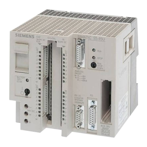
2.1.1 Design of the S5-90U S5-90U: LEDs, Controls and Interfaces 32.0 .1 33.0 INPUT 10x24VDC Power AC 100mA OUTPUT SIEMENS Battery SIMATIC S5-90U IM 90 STOP 6ES5 090- 8MA01 OUTPUT 6x RELAIS 32.0 32.1... - Page 36 Technical Description S5-90U/S5-95U S5-90U: Pin Assignments of the Programmer Interface The programmer interface is non-floating. The signal lines are connected to a 15-pin sub D socket. M (reference potential) M (reference potential) (TTY outgoing line -) OUT- +5.2 V (supply for external loads) (TTY outgoing line +) OUT+ 20 mA (TTY current source)
-
Page 37: Design Of The S5-95U
S5-90U/S5-95U Technical Description 2.1.2 Design of the S5-95U S5-95U: LEDs, Controls and Interfaces STOP Battery STOP COPY DC 24V Battery compartment Front panel connector for digital inputs (I 32.0 to I 33.7) and for digital outputs (Q 32.0 to Q 33.7) Battery low LED ON/OFF switch LED display for digital inputs and outputs... - Page 38 Technical Description S5-90U/S5-95U S5-95U : Pin Assignments of the Programmer Interface The programmer interface is non-floating. The signal lines are connected to a 15-pin sub D socket. (reference potential) (reference potential) (TTY outgoing line -) OUT- +5.2 V (supply for external loads) (TTY outgoing line +) OUT+ 20 mA (TTY current source)
-
Page 39: Internal Electrical Configuration
S5-90U/S5-95U Technical Description Internal Electrical Configuration 2.2.1 Internal Electrical Configuration of the S5-90U The S5-90U's onboard I/Os allow a floating configuration. The ten onboard inputs have a common ground connection. The ground connection is attached to the negative pole of the PLC's 24 V DC voltage source. Optocouplers separate all inputs from the control circuit's ground. -
Page 40: 2.2.2 Internal Electrical Configuration Of The S5-95U
Technical Description S5-90U/S5-95U 2.2.2 Internal Electrical Configuration of the S5-95U The digital onboard I/Os for the S5-95U are galvanically isolated from the control circuit by optocouplers and allow a floating configuration. The digital onboard I/Os are divided into groups (= number of inputs and outputs with separate 24 V DC connection) •... -
Page 41: Principle Of Operation Of The Plcs
S5-90U/S5-95U Technical Description Principle of Operation of the PLCs This section briefly describes the PLC's functional units processing your STEP 5 program. 2.3.1 Functional Units S5-100U S5-90U module(s) IM 90 S5-95U The IM 90 is required for Proces- • Operating system the S5-90U sor and only. - Page 42 Technical Description S5-90U/S5-95U The operating system is stored in a ROM. It is thus fixed and cannot be changed. All dynamic variables are stored in the RAM. These are the following: • STEP 5 program and compiled program. The STEP 5 program cannot be processed unless it is transformed by a compiler into a form that can be interpreted by the processor and arithmetic unit.
- Page 43 S5-90U/S5-95U Technical Description Note An interference pulse lasting approximately 150 µs is generated on switching on the supply voltage to the onboard I/O. "Normal" inputs do not accept this pulse. High-speed inputs (e. g. counters) recognize this pulse as a singal. Programmer Interface Interface for a programmer or operator control and monitoring device (TD or OP).
-
Page 44: Peculiarities Of The Plcs
Technical Description S5-90U/S5-95U 2.3.2 Peculiarities of the PLCs The STEP 5 program developed by the user is not directly executed by the processor and arithmetic unit. It must first be translated by a compiler so that it can be interpreted by the processor and arithmetic unit. - Page 45 S5-90U/S5-95U Technical Description Only the compiled program is executed by the processor and arithmetic unit whereas the STEP 5 program remains in the RAM. It can be read back into the programmer. In comparison with other PLCs whose processors and arithmetic units are able to process the STEP 5 program, this procedure involves some peculiarities when using the S5-90U/95U PLCs.
- Page 46 EWA 4NEB 812 6115-02b...
-
Page 47: Installation Guidelines
Installation Guidelines Mounting the PLC ........3 - 1 Mounting the PLCs with External I/Os . - Page 48 Figures Mounting the S5-90U on a Wall ....... 3 - 2 Drilling Template for Mounting the S5-90U Using Wall Brackets .
- Page 49 S5-90U/S5-95U Installation Guidelines Installation Guidelines Mounting the PLC The PLC can either be mounted to a wall using wall brackets or snapped onto a standard mounting rail. Table 3-1. Mounting Options for the PLCs S5-90U S5-95U Fixing part Without With external Without With external external I/Os...
- Page 56 Installation Guidelines S5-90U/S5-95U Mounting the PS 931 Power Supply Module Hook the power supply module onto the standard mounting rail. Press the module down firmly until the slide snaps onto the rail. Removal: Turn off the 115 V/230 V AC power supply. Loosen the connections between the PLC and the power supply module.
- Page 60 Installation Guidelines S5-90U/S5-95U Installing the interface module Hook the interface module to the standard mounting rail. Swing the interface module back until the slide on the bottom snaps into place on the rail. Use the flat ribbon cable to connect the module to the last bus unit. Use connecting cable 712-8 to join the two interface modules (in the case of the IM 318).
-
Page 61: Cabinet Mounting
S5-90U/S5-95U Installation Guidelines 3.2.5 Cabinet Mounting To help prevent noise, mount the programmable controller on a metal plate. The connections between the mounting rails should have a low impedance. Make sure that the system is bonded to earth. You can use the 8LW system or the 8LX system mounting plates (see Catalog NV 21). A minimum clearance of 210 mm between two mounting rails should be adhered to. - Page 62 Installation Guidelines S5-90U/S5-95U Vertical Mounting You can also mount the standard mounting rails vertically and then attach the modules one over the other. Because heat dissipation by convection is less effective in this case, the maximum ambient temperature allowed is 40° C (104° F). Use the same minimum clearances for a vertical configuration as for a horizontal configuration.
-
Page 63: Connection Methods
S5-90U/S5-95U Installation Guidelines Wiring 3.3.1 Connection Methods The following wiring techniques can be used for the S5-90U and S5-95U: • Standard screw-type connection • SIGUT screw-type connection • Crimp snap-in connection Examples of Standard Screw-Type Terminals: • Screw-type terminals of the S5-90U •... -
Page 68: 3.3.4 Connecting The Onboard I/Os Of The S5-90U
Installation Guidelines S5-90U/S5-95U 3.3.4 Connecting the Onboard I/Os of the S5-90U The signal cables for the onboard I/Os can be connected directly to the standard terminal on the PLC. Connecting Digital Inputs The digital inputs, located on the top of the PLC, are numbered with fixed bit addresses ranging from 32.0 to 33.1. - Page 69 S5-90U/S5-95U Installation Guidelines Connecting the Interrupt and Counter Inputs Terminal 33.0 can be used as interrupt input and terminal 33.1 as counter input. If you wish to use terminal 33.0 as interrupt input, set the parameters in DB 1 accordingly (see Chapter 10).
-
Page 70: 3.3.5 Connecting The Onboard I/Os Of The S5-95U
Installation Guidelines S5-90U/S5-95U 3.3.5 Connecting the Onboard I/Os of the S5-95U Use the following parts to connect the onboard I/Os of the S5-95U. • 40-pin front connector for digital inputs and outputs • 15-pin sub D connector for analog inputs and outputs •... - Page 71 S5-90U/S5-95U Installation Guidelines Connecting Analog Inputs and Outputs Attach the analog I/O signal cables to the PLC using a sub D connector. There are eight analog inputs and one analog output available. Depending on the terminal assignment, the analog output is either a "current"...
-
Page 72: Connecting External I/Os
Installation Guidelines S5-90U/S5-95U Connecting Interrupt and Counter Inputs There are four interrupt inputs and two counter inputs available in the S5-95U. The interrupt inputs and counter inputs have the same internal grounding point as the PLC. Use a 9-pin sub D connector to connect the signal cables for these inputs to the PLC. -
Page 73: Electrical Configuration With External I/Os
S5-90U/S5-95U Installation Guidelines Electrical Configuration with External I/Os 3.4.1 Electrical Configuration of the S5-90U with External I/Os Figure 3-26 shows a possible configuration. Pay attention to the following points when you design your configuration. • You must have a main switch (1) in accordance with VDE 0100 for your PLC, the sensors, and the actuators. - Page 74 Installation Guidelines S5-90U/S5-95U Grounded Configuration of an S5-90U S5-90U IM 90 DO DO 230 V AC Figure 3-26. Configuration for the S5-90U with External I/Os and a 115/220V AC Power Supply Ungrounded configurations are not possible for the S5-90U! 3-26 EWA 4NEB 812 6115-02b...
-
Page 75: Electrical Configuration Of The S5-95U With External I/Os
S5-90U/S5-95U Installation Guidelines 3.4.2 Electrical Configuration of the S5-95U with External I/Os Figures 3-27 and 3-28 show different configuration possibilities. Pay attention to the following points when you design your configuration. • You must have a main switch (1) in accordance with VDE 0100 for your PLC, the sensors, and the actuators. - Page 76 Installation Guidelines S5-90U/S5-95U Grounded Configuration of an S5-95U S5-95U Figure 3-27. Grounded Configuration of the S5-95U with a 24 V DC Power Supply (with Safe Electrical Isolation in Accordance with DIN VDE 0160) for a Programmable Controller and Non-Floating, External I/Os 3-28 EWA 4NEB 812 6115-02b...
- Page 77 S5-90U/S5-95U Installation Guidelines Ungrounded Configuration of an S5-95U 1 µF/ 100 K Isolated standard 500 V AC mounting rail S5-95U DO DO Figure 3-28. Ungrounded Configuration: 24 V DC Power Supply (with Safe Electrical Isolation According to VDE 0160) for Use with a Programmable Controller and External I/Os Interference voltages are discharged to the ground conductor (PE) via a capacitor.
-
Page 78: 3.4.3 Connecting Non-Floating And Floating Modules
Installation Guidelines S5-90U/S5-95U 3.4.3 Connecting Non-Floating and Floating Modules The following sections show the special features involved in installations with nonfloating and floating modules. Installation with Non-Floating Modules In installations with non-floating modules, the reference potential of the control circuit (M ) and internal the load circuits (M... - Page 79 S5-90U/S5-95U Installation Guidelines Note It is imperative that you connect the reference potential of the load power supply unit with the L- terminal of the module in the case of 24 V DC digital output modules. If this connection is missing (e.g. wirebreak), a current of typically 15 mA can flow at the outputs.
- Page 80 Installation Guidelines S5-90U/S5-95U Warning If you use non-floating I/O modules, you must provide an external connection between the chassis ground of the non-floating I/O module and the chassis ground of the CPU. Example of a Floating Configuration with Digital Modules A floating configuration is required in the following situations.
-
Page 81: Wiring Arrangement, Shielding And Measures Against Electromagnetic Interference
S5-90U/S5-95U Installation Guidelines Wiring Arrangement, Shielding and Measures against Electromagnetic Interference This section describes the wiring arrangements for bus cables, signal cables, and power supply cables that guarantee the electromagnetic compatibility (EMC) of your installation. 3.5.1 Running Cables Inside and Outside a Cabinet Dividing the lines into the following groups and running the groups separately will help you to achieve electromagnetic compatibility (EMC). -
Page 82: Running Cables Outside Buildings
Install these protective elements at the point where the cable enters the building. Note Lightning protection measures always require an individual assessment of the entire system. If you have any questions, please consult your local Siemens office or any company specializing in lightning protection. Grounding Make certain that you have sufficient equipotential bonding between the devices. -
Page 83: Equipotential Bonding
S5-90U/S5-95U Installation Guidelines 3.5.3 Equipotential Bonding Potential differences may occur between separate sections of the system if • Programmable controllers and I/Os are connected via non-floating interface modules or • Cables are shielded at both ends but grounded via different sections of the system. Potential differences may be caused, for instance, by differences in the system input voltage. -
Page 84: Shielding Cables
Installation Guidelines S5-90U/S5-95U 3.5.4 Shielding Cables Shielding is a measure to weaken (attenuate) magnetic, electric or electromagnetic interference fields. Interference currents on cable shields are discharged to ground over the shield bar which has a conductive connection to the housing. So that these interference currents do not become a source of noise in themselves, a low-resistance connection to the protective conductor is of special importance. -
Page 85: Special Measures For Interference-Free Operations
S5-90U/S5-95U Installation Guidelines Note the following when connecting the cable shield: • Use metal cable clamps for fixing the braided shield. The clamps have to enclose the shield over a large area and make good contact (see Figure 3-32). • Connect the shield to a shield bar immediately at the point where the cable enters the cabinet. - Page 86 Installation Guidelines S5-90U/S5-95U Mains Connection for Programmers Provide a power connection for a programmer in each cabinet. The plug must be supplied from the distribution line to which the protective ground for the cabinet is connected. Cabinet Lighting Use, for example, LINESTRA® lamps for cabinet lighting. Avoid the use of fluorescent lamps since these generate interference fields.
-
Page 87: Start-Up And Programmer Functions
Start-Up and Programmer Functions Operating Instructions ....... . 4 - 1 4.1.1 Programmable Controller Operator Panel . - Page 88 Figures Operator Panel of the S5-90U ....... . 4 - 1 Operator Panel of the S5-95U .
-
Page 90: Operating Modes
Start-Up and Program Tests S5-90U/S5-95U 4.1.2 Operating Modes "STOP" Operating Mode • The program is not executed. • The current values for timers, counters, flags, and process images are saved when the "STOP" operating mode begins. • The onboard outputs and the output modules are disabled; i.e. the digital outputs have the "0" signal state and the analog outputs are de-energized. -
Page 91: Performing An Overall Reset Of The Programmable Controller
S5-90U/S5-95U Start-Up and Program Tests 4.1.3 Performing an Overall Reset of the Programmable Controller You should perform an overall reset before you input a new program. An overall reset achieves the following: • All not integrated program and data blocks are erased. •... -
Page 92: Starting Up A System
Start-Up and Program Tests S5-90U/S5-95U Starting Up a System The following section contains suggestions for configuring and starting up a system containing programmable controllers. 4.2.1 Suggestions for Configuring and Installing the Programmable Controller A programmable controller is often used as a component in a larger system. The suggestions contained in the following warning are intended to help you safely install your programmable controller. -
Page 93: Steps For Starting Up The Programmable Controller
S5-90U/S5-95U Start-Up and Program Tests 4.2.2 Steps for Starting Up the Programmable Controller Steps for Starting Up the S5-90U and the S5-95U with and without External I/Os Table 4-1. Starting Up the S5-90U and the S5-95U with and without External I/Os Procedures Indications on S5-90U/S5-95U Disconnect system and PLC from... - Page 94 Start-Up and Program Tests S5-90U/S5-95U Table 4-1. Starting Up the S5-90U and S5-95U with and without External I/Os (Continued) Procedures Indications on S5-90U/S5-95U Insert battery into PLC. • PLC: Green operating mode LED lit; green signal status LEDs of the inputs lit. •...
- Page 95 S5-90U/S5-95U Start-Up and Program Tests Table 4-1. Starting Up the S5-90U and S5-95U with and without External I/Os (Continued) Procedures Indications on S5-90U/S5-95U Load program from memory LEDs (see Section 4.3). submodule into PLC if available (see Section 4.3). Otherwise, load program from programmer.
-
Page 96: Loading The Program Into The Plc
Start-Up and Program Tests S5-90U/S5-95U Loading the Program into the PLC The STEP 5 program is loaded into the RAM of the PLC. It includes all OBs, PBs, FBs, SBs and DBs, including DB1. The program can be loaded from a programmer connected to the PLC (on-line mode). -
Page 97: Loading The Program Manually
S5-90U/S5-95U Start-Up and Program Tests 4.3.2 Loading the Program Manually (S5-95U) Manual loading of the program is possible only in connection with the S5-95U. When you manually load a program, it is copied from the memory submodule into the PLC's program memory. -
Page 98: Saving A Program
Start-Up and Program Tests S5-90U/S5-95U Saving a Program You can save the STEP 5 program in the RAM of the PLC. The STEP 5 program includes all valid OBs, PBs, FBs, SBs and DBs, including DB1. The program can be saved in a program file or on a memory submodule using a programmer (on-line mode). -
Page 99: Function Of The Back-Up Battery
S5-90U/S5-95U Start-Up and Program Tests 4.4.2 Function of the Back-Up Battery If the power fails or the programmable controller is switched off, the contents of the internal memory are stored (retentive) only if a back-up battery is connected. When the programmable controller is switched on, the following contents are available: •... -
Page 100: Overview Of Programmer Functions
Start-Up and Program Tests S5-90U/S5-95U 4.5.1 Overview of Programmer Functions The following table lists the complete scope of functions available at the programmer interface. Table 4-2. Overview of Functions Programmer Function Possible for Possible for S5-90U S5-95U Designation Abbreviation Input block INPUT Output block OUTPUT... -
Page 101: Peculiarities Of The Programmer Functions For The S5-90U And S5-95U
S5-90U/S5-95U Start-Up and Program Tests 4.5.2 Peculiarities of the Programmer Functions for the S5-90U and S5-95U "Input block" Programmer Function for the S5-95U If the PLC is switched to RUN and if you want to modify or transfer blocks, the scan time is automatically extended. - Page 102 EWA 4NEB 812 6115-02b...
-
Page 103: Diagnostics And Trouble Shooting
Diagnostics and Trouble Shooting Diagnostic Byte ........5 - 1 LED Error Display . - Page 104 Figures Diagnostic Byte for the S5-90U ....... 5 - 1 Diagnostic Byte for the S5-95U .
- Page 105 S5-90U/S5-95U Diagnostics and Trouble Shooting Diagnostics and Trouble Shooting Diagnostic Byte The diagnostic byte offers you another means of controlling the process sequence. The diagnostic byte displays the following: • Whether a counter has reached the comparison value (counter overflow) •...
- Page 106 Diagnostics and Trouble Shooting S5-90U/S5-95U Diagnostic Byte Assignment for the S5-95U Bit no.: CB CA IB 35 Interrupt at I 34.3 No interrupt at I 34.3 Interrupt at I 34.2 No interrupt at I 34.2 Interrupt at I 34.1 No interrupt at I 34.1 Interrupt at I 34.0 No interrupt at I 34.0 Battery backup available...
- Page 107 S5-90U/S5-95U Diagnostics and Trouble Shooting Reading and Resetting the Diagnostic Byte In the central program, you can read in and evaluate the data stored in the diagnostic byte using binary operations (e.g., A I 35.0) or load operations (e.g., L IB 35). Example Explanation The diagnostic byte is...
- Page 108 Diagnostics and Trouble Shooting S5-90U/S5-95U Interrupt Analysis Using the Programmer The operating system sets various "analysis" bits in the case of any malfunction. These bits can be read by means of the ISTACK function of the programmer. 5.3.1 "ISTACK" Analysis Function The interrupt stack is an internal programmable controller memory area where the causes of mal- functions are stored.
- Page 109 S5-90U/S5-95U Diagnostics and Trouble Shooting ISTACK Display on the 710/730/750 and 770 Programmers The ISTACK display is divided up into two different programmer screen forms. The first screen form shows the control bits of the ISTACK, the second one basically lists the causes of errors. Table 5-2 shows the control bit screen form of the ISTACK.
-
Page 110: S5-90U And S5-95U
Diagnostics and Trouble Shooting S5-90U/S5-95U Tables 5-4 and 5-5 list the meanings fo the abbreviations used in the ISTACK display on the programmer. Table 5-4. Abbreviations for Control Bits and Causes of Errors Abbreviations of Error/Fault Causes Abbreviations of Control Bits Relevant for Relevant for S5-90U and S5-95U S5-90U and S5-95U (= Error IDs) -
Page 111: Meanings Of The Istack Displays For Errors Occurring During Restart And Program Execution
S5-90U/S5-95U Diagnostics and Trouble Shooting 5.3.2 Meanings of the ISTACK Displays for Errors Occurring During Restart and Program Execution You can use Table 5-6 to determine the cause of an interrupt in program processing. The PLC always enters the "STOP" mode. Note If DB1 is stated as the cause of the error in the ISTACK, refer to Section 9.4.5 for error elimination. -
Page 112: During Copying The Program
Diagnostics and Trouble Shooting S5-90U/S5-95U Table 5-6. Interrupt Analysis (Continued) ISTACK Cause of Error Error Elimination Display SUF* Substitution error: - Change actual parameter. - Function block called with an incorrect actual parameter. - For interrupt- and time-driven processing: - Disable interrupts. integral FB call while another FB is processed. -
Page 113: Program Errors
S5-90U/S5-95U Diagnostics and Trouble Shooting Program Errors The ISTACK displays two types of program errors: • Errors recognized by the compiler when compiling the program ("Compiler error", e.g. "NNN") • Errors recognized during program execution (runtime errors, such as "SUF" and "TRAF") 5.4.1 Determining an Error Address ”Compiler Error”... -
Page 114: 5.4.2 Program Tracing With The "Bstack" Function
Diagnostics and Trouble Shooting S5-90U/S5-95U Runtime Errors If a runtime error has occurred, the STEP address counter specifies the initial address of the errored block. The relative STEP address counter (REL-SAC) has the value "0000". In the case of the "SUF" and "TRAF" runtime errors, you can use a "trick" to determine the correct address of the error (for S5-95U only). - Page 115 S5-90U/S5-95U Diagnostics and Trouble Shooting Example: Program scanning was interrupted at function block FB2. The programmable controller went into the "STOP" mode with the error message "TRAF" (because of incorrect DB access, e.g., DB5 is two words long, DB3 is ten words long). "BSTACK"...
-
Page 116: Faults In The External I/Os
Diagnostics and Trouble Shooting S5-90U/S5-95U Faults in the External I/Os Fault Module with Power Check fault LED supply ok? supply leads (red) ? Is module addressable via Replace Is red LED lit? connection PII, PIQ (STATUS bus unit VAR, FORCE VAR) ? Replace mod. -
Page 117: System Parameters
S5-90U/S5-95U Diagnostics and Trouble Shooting System Parameters The "SYSPAR" programmer function can be used to read the system parameters (e.g. PLC software version) of the PLC (see Programmer Manual). The PLC does not Enter the "RUN" Mode Suppose the programmable controller cannot be brought into the "RUN" mode although all feasible causes of errors concerning parameterization (DB1) and the STEP 5 program can be excluded. - Page 118 EWA 4NEB 812 6115-02b...
-
Page 119: Addressing And Access To I/Os
Addressing and Access to I/Os Addressing the Onboard I/Os ......6 - 1 Addressing the External I/Os ......6 - 2 6.2.1 Slot Numbering . - Page 120 Figures Address Assignments for External I/Os ......6 - 2 Consecutive Numbering of Slots in a Single-Tier Configuration .
-
Page 121: Addressing And Access To I/Os
S5-90U/S5-95U Addressing and Access to I/Os Addressing and Access to I/Os The S5-90U and the S5-95U have two types of inputs and outputs. The inputs and outputs located on the programmable controller itself are called onboard I/Os. The S5-100U modules that expand your programmable controller are called external I/Os. -
Page 122: Addressing The External I/Os
Addressing and Access to I/Os S5-90U/S5-95U Addressing the External I/Os The addresses for the external I/Os are slot oriented. This means that once a module is snapped onto its slot on the bus unit, it is assigned a slot number and thus a fixed address in one or both of the process images. - Page 123 S5-90U/S5-95U Addressing and Access to I/Os If the programmable controller consists of more than one tier, numbering of the expansion tiers is continued at the slot on the extreme left. Slot numbers IM 316 26 27 IM 316 23 24 IM 316 14 15 IM 316...
- Page 124 Addressing and Access to I/Os S5-90U/S5-95U Example: Expanding from 14 to 18 Slots Existing configuration 12 13 2 3 4 5 6 New bus units Correct expansion procedure 12 13 16 17 The new bus units are added at the right. The interface module is moved correspondingly to the right.
-
Page 125: Digital Modules
S5-90U/S5-95U Addressing and Access to I/Os 6.2.2 Digital Modules Only two items of information ("0" or "1") per channel can be transferred either from or to a digital module. Digital modules are addressed channel by channel in the case of bit operations. There are two types of digital modules with different address ranges: •... - Page 126 Addressing and Access to I/Os S5-90U/S5-95U Digital Modules with more than Eight Channels Slot No. 64.0 to 64.7 72.0 to 72.7 120.0 to 120.7 The following 65.0 to 65.7 73.0 to 73.7 121.0 to 121.7 slots are not available for digital modules with more than eight channels...
-
Page 127: Analog Modules
S5-90U/S5-95U Addressing and Access to I/Os 6.2.3 Analog Modules Whereas either one "0" or "1" bit per cannel can be transferred from one digital module to another, 65536 different items of information (16 bits) can be exchanged on each channel between two analog modules. -
Page 128: Function Modules
Addressing and Access to I/Os S5-90U/S5-95U 6.2.4 Function Modules The address assignments vary for the individual function modules. Some function modules are addressed like digital modules, some like analog modules. For module addressing refer either to Chapter 16, "Function Modules", or to the Manual for a specific module. -
Page 129: Process Image And Access To I/Os
S5-90U/S5-95U Addressing and Access to I/Os Process Image and Access to I/Os The process input image (PII) includes information on inputs; information on outputs is written into the process output image (PIQ). The PII and the PIQ occupy 128 bytes each in the RAM of the PLC. I/O Areas and their Addresses in the Process Image of the S5-90U Table 6-2. - Page 130 Addressing and Access to I/Os S5-90U/S5-95U I/O Areas and their Addresses in the Process Image of the S5-95U Table 6-3. S5-95U: Structure of the PII and PIQ Process Input Image (PII) Process Output Image (PIQ) Address Address Assignment Assignment in PII in PIQ 0.0 to 31.7 Digital inputs of the external...
-
Page 131: Access To I/Os During Cyclic Program Execution
S5-90U/S5-95U Addressing and Access to I/Os 6.3.1 Access to I/Os During Cyclic Program Execution Direct I/O Access Direct I/O access enables the exchange of information with the I/Os without previously writing this information either into the process input image or process output image. In this way, the values currently present at the inputs are processed by the program and the result immediately routed to the outputs. - Page 132 Addressing and Access to I/Os S5-90U/S5-95U The following Figure illustrates the procedures for direct and indirect I/O access. Cyclic Program Onboard External I/Os I/Os Read data Process input image (PII) OB1: Cyclic program Read value from PII ACCU 1 IW x Read value direct from onboard I/Os AKKU 1...
-
Page 133: Access To I/Os During Time-Controlled Program Execution
S5-90U/S5-95U Addressing and Access to I/Os 6.3.2 Access to I/Os During Time-Controlled Program Execution (for S5-95U only) The S5-95U enables time-controlled program execution with the OB 13 (see Section 9.1.3). There are two possibilities for accessing the I/Os during time-controlled program execution: •... - Page 134 Addressing and Access to I/Os S5-90U/S5-95U The following Figure illustrates the procedures for direct and indirect I/O access. Cyclic Program Onboard External I/Os I/Os Process input image (PII) Time-controlled program OB1: Cyclic program Read Interrupt process input image data (interrupt PII) OB13: Time-controlled prog.
-
Page 135: Calculating The Scan Time And Response Time
S5-90U/S5-95U Addressing and Access to I/Os Calculating the Scan Time and Response Time Scan Time The scan time is the time required for one program cycle. The scan time includes the following: • Transfer time for the process image (PII and PIQ) •... - Page 136 Addressing and Access to I/Os S5-90U/S5-95U Shortest Possible Response Time: The input status changes immediately before the PII is read in. The change of the input signal is therefore taken into account in the PII. Operating system Res- ponse time User The input signal change is processed by the control program.
- Page 137 S5-90U/S5-95U Addressing and Access to I/Os Longest Possible Response Time: The status of the respective input changes while the PII is being read. The input signal change is not taken into account in the PII. Operating system User program Res- ponse The input signal change is now entered in the PII.
- Page 138 Addressing and Access to I/Os S5-90U/S5-95U Note Note the following points if you wish to reduce the scan time and the response time: • DB1 enables you to parameterize the number of analog inputs to be read into the PII cyclically from the onboard I/Os of the S5-95U (see Chapter 12).
- Page 139 S5-90U/S5-95U Addressing and Access to I/Os Table 6-7. Bits Assigned to the Various Modules in the PII/PIQ Bits Assigned to Module Module in the PII/PIQ • Digital modules with four channels • Diagnostic module • Comparator module • Timer module •...
- Page 140 Addressing and Access to I/Os S5-90U/S5-95U 4. Execution Time for Internal Timers All internal timers parameterized (see 6.5) are updated by the operating system in intervals of 10 ms. The time required by the operating system for a single updating cycle of all timers parameterized is as follows: S5-95U: =(number of timers parameterized)
- Page 141 S5-90U/S5-95U Addressing and Access to I/Os Calculating the Scan Time The scan time includes the following: • Process image transfer time • Operating system runtime • Program execution time • Execution time for internal timers Example: Your S5-95U configuration includes an IP 266 and an IP 267. All analog channels of the onboard I/Os are to be read into the PII.
- Page 142 Addressing and Access to I/Os S5-90U/S5-95U Calculating the Response time The response time includes the following: • 3 x process image transfer time+ • 3 x operating system runtime+ • 2 x program execution time+ • Execution time for internal timers+ •...
-
Page 143: Start-Up With/Without External I/Os And Parameterization Of Internal Timers (S5-95U Only)
S5-90U/S5-95U Addressing and Access to I/Os Start-Up with/without External I/Os and Parameterization of Internal Timers (S5-95U only) You can set some system characteristics in the "SDP:" (System-Dependent Parameters) parameter block of data block 1 (DB1). The syntax of DB1 and the procedure for parameterizing DB1 are described in Section 9.4. - Page 144 Addressing and Access to I/Os S5-90U/S5-95U Example: The program only requires 25 internal timers (T0 to T24) and you want to be certain that the programmable controller starts up only if the external I/O modules are ready. How to proceed (see Section 9-4): Display DB1 on the programmer.
-
Page 145: Introduction To Step 5
Introduction to STEP 5 Writing a Program ........7 - 1 7.1.1 Methods of Representation . - Page 146 Figures Nesting ..........7 - 5 Structure of a Block Header .
-
Page 147: Writing A Program
S5-90U/S5-95U Introduction to STEP 5 Introduction to STEP 5 This chapter explains how to program the S5-90U/S5-95U. It describes how to write a program, how the program is structured, the types of blocks the program uses, and the number representation of the STEP 5 programming language. -
Page 148: Operand Areas
Introduction to STEP 5 S5-90U/S5-95U The STEP 5 programming language has the following three operation types. • Basic • Supplementary • System Table 7-1 provides further information on these operations. Table 7-1. Comparison of Operation Types STEP 5 PROGRAMMING LANGUAGE Supplementary Basic Operations System Operations... -
Page 149: Program Structure
S5-90U/S5-95U Introduction to STEP 5 Program Structure The programs of both PLCs can either be linear or structured. Sections 7.2.1. and 7.2.2 describe these program types. 7.2.1 Linear Programming Programming individual operations in one section (block) is sufficient for handling simple automation jobs. -
Page 150: Structured Programming
Introduction to STEP 5 S5-90U/S5-95U 7.2.2 Structured Programming To solve complex tasks, it is advisable to divide a program into individual, self-contained program parts (blocks). This procedure has the following advantages: • Simple and clear programming, even for large programs •... - Page 151 S5-90U/S5-95U Introduction to STEP 5 The program uses block calls to exit one block and jump to another. You can therefore nest pro- gram, function, and sequence blocks randomly in up to 16 levels. Note When calculating the nesting depth, note that the operating system of the programmable controller can call an organization block under certain circumstances (e.
-
Page 152: Block Types
Introduction to STEP 5 S5-90U/S5-95U Block Types The following Table lists the most important characteristics of the individual block types. Table 7-2. Comparison of Block Types Block types Characteristics Number in S5-90U OB1, 3, 21, 22 PB0 to PB63 FB0 to FB63 DB2 to DB63 Number in S5-95U... - Page 153 S5-90U/S5-95U Introduction to STEP 5 Block Structure Each block consists of the following parts. • Block header specifying the block type, number, and length. The programmer generates the block header when it transforms the block. • Block body with the STEP 5 program or data. Synchronization Absolute pattern...
-
Page 154: Organization Blocks (Obs)
Introduction to STEP 5 S5-90U/S5-95U 7.3.1 Organization Blocks (OBs) Organization blocks constitute the interface between the operating system and the control program, and coordinate the execution of the control program. OBs can be grouped according to their tasks and called up as described below: •... - Page 155 S5-90U/S5-95U Introduction to STEP 5 Figure 7-3 shows how to set up a structured control program. It also illustrates the significance of organization blocks. OB21/OB22 SB1* FB61 Operating system Control program * Only for the S5-95U Figure 7-3. Example of Organization Block Use EWA 4NEB 812 6115-02b...
-
Page 156: Program Blocks (Pbs)
Introduction to STEP 5 S5-90U/S5-95U 7.3.2 Program Blocks (PBs) Self-contained program parts are programmed in program blocks. Special feature: Control functions can be represented graphically in program blocks. Call Block calls JU and JC activate program blocks. You can program these operations in all block types except data blocks. - Page 157 S5-90U/S5-95U Introduction to STEP 5 Block Header Besides the block header, function blocks have organizational forms that other blocks do not have. A function block's memory requirements consist of the following. • Block header as for other blocks (five words) (see Figure 7-2) •...
- Page 158 Introduction to STEP 5 S5-90U/S5-95U When assigning parameters, enter all block parameter specifications. Block header Name NAME: EXAMPLE DES: IN 1 Block parameter DES: IN 2 Formal operand Block parameter DES: OUT 1 A Data type Parameter type : A = IN 1 : A = IN 2 Control program...
- Page 159 S5-90U/S5-95U Introduction to STEP 5 Table 7-3. Block Parameter Types and Data Types with Permissible Actual Operands (only for S5-95U) Parameter Data Type Permissible Actual Operands Type I, Q for an operand with bit address x.y Inputs x.y Outputs x.y Flags for an operand with byte address Input bytes QB x...
- Page 160 Introduction to STEP 5 S5-90U/S5-95U The call consists of the following parts. • Call statement unconditional call ( J ump U nconditional) - JU - JC call if RLO = 1 ( J ump C onditional) • Parameter list (only if block parameters were defined in the FB) Function blocks can be called only if they have been programmed.
-
Page 161: Data Blocks (Dbs)
S5-90U/S5-95U Introduction to STEP 5 Executed program NAME : EXAMPLE DES : X1 I DES : X2 I DES : X3 Q BI : JU : A = X1 NAME : EXAMPLE First call : A = X2 := = : I 32.0 I 32.0 Parameter list for... - Page 162 Introduction to STEP 5 S5-90U/S5-95U Programming Data Blocks Begin programming a data block by specifying a block number between 2 and 63 for the S5-90U, and between 2 and 255 for the S5-95U. DB0 is reserved for the operating system, DB1 for setting parameters for internal functions.
-
Page 163: Processing Blocks
S5-90U/S5-95U Introduction to STEP 5 Processing Blocks Earlier sections in this chapter described how to use blocks. Chapter 8 introduces all of the operations required to work with blocks. You can change any blocks that have already been programmed. The following sections will deal only briefly with the different ways you can change blocks. -
Page 164: Number Representation
Introduction to STEP 5 S5-90U/S5-95U You can use the COMPRESS programmer function to clean up program memory. If there is a power failure during the compress operation when a block is being shifted and block shifting can not be completed, the programmable controller remains in the STOP mode. The ”NINEU”... - Page 165 S5-90U/S5-95U Introduction to STEP 5 You can work with binary-coded decimals to program timers and counters in the decimal system. BCD tetrads are defined in the range of 0 to 9. Example: 12-bit timer or counter value in BCD and decimal formats Word No.
- Page 166 Introduction to STEP 5 S5-90U/S5-95U You can use the ”LD” operation to load a binary number as a BCD number for timer and counter values. Example: Comparing a count in counter 1 with decimal number 499. The comparison value must be stored in the accumulator by means of the load operation.
- Page 167 STEP 5 Operations Basic Operations ........8.1.1 Boolean Logic Operations .
- Page 168 Figures Accumulator Structure ........8-10 Execution of the Load Operation .
-
Page 169: Step 5 Operations
S5-90U/S5-95U STEP 5 Operations STEP 5 Operations The STEP 5 programming language has the following three operation types. • Basic Operations include functions that can be executed in organization, program, sequence, and function blocks. Except for the addition (+F), subtraction (-F), and organizational ope- rations, the basic operations can be input and output in the statement list (STL), control system flowchart (CSF), or ladder diagram (LAD) methods of representation. -
Page 170: Boolean Logic Operations
STEP 5 Operations S5-90U/S5-95U 8.1.1 Boolean Logic Operations Table 8-1 provides an overview of Boolean logic operations. Examples follow the table. Table 8-1. Overview of Boolean Logic Operations Operation Operand Meaning Combine AND operations through logic OR Combine the result of the next AND logic operation (RLO) with the previous RLO through logic OR. - Page 171 S5-90U/S5-95U STEP 5 Operations AND Operation The AND operation scans to see if various conditions are satisfied simultaneously. Example Circuit Diagram Output Q32.5 is ”1” when all three inputs are ”1”. I32.0 The output is ”0” if at least one input is ”0”. The number of scans and the sequence of the logic I32.1 statements are optional.
- Page 172 STEP 5 Operations S5-90U/S5-95U AND before OR Operation Example Circuit Diagram Output Q32.5 is ”1” when at least one AND condition has been satisfied. I32.0 I32.2 Output Q32.5 is ”0” when neither of the two AND con- ditions has been satisfied. I32.1 I32.3 Q32.5...
- Page 173 S5-90U/S5-95U STEP 5 Operations OR before AND Operation Example Circuit Diagram Output Q32.5 is ”1” when one of the following conditions has been satisfied: I32.0 I32.2 I32.3 • Input I32.0 is ”1”. • Input I32.1 and either input I 32.2 or I 32.3 are ”1”. Output Q32.5 is ”0”...
- Page 174 STEP 5 Operations S5-90U/S5-95U OR before AND Operation Example Circuit Diagram Output Q32.5 is ”1” when both OR conditions have been satisfied. I32.0 I32.1 Output Q32.5 is ”0” when at least one OR condition has not been satisfied. I32.2 I32.3 Q32.5 I32.0 >...
-
Page 175: Set/Reset Operations
S5-90U/S5-95U STEP 5 Operations 8.1.2 Set/Reset Operations Set/reset operations store the result of logic operation (RLO) formed in the processor. The stored RLO represents the signal state of the addressed operand. Storage can be dynamic (assignment) or static (set and reset). Table 8-2 provides an overview of the set/reset operations. Examples follow the table. - Page 176 STEP 5 Operations S5-90U/S5-95U Flip-Flop for a Latching Signal Output Example Circuit Diagram A ”1” at input I32.1 sets flip-flop Q32.5 (signal state ”1”). If the signal state at input I32.5 changes to ”0”, the state of output Q32.5 is maintained, i.e., the signal is latched. I32.0 I32.1 A ”1”...
- Page 177 S5-90U/S5-95U STEP 5 Operations RS Flip-Flop with Flags Example Circuit Diagram A ”1” at input I32.1 sets flip-flop F 1.7 (signal state ”1”). If the signal state at input I32.1 changes to ”0”, the state of flag F 1.7 is maintained, i.e., the signal is latched. A ”1”...
-
Page 178: Load And Transfer Operations
STEP 5 Operations S5-90U/S5-95U 8.1.3 Load and Transfer Operations Use load operations and transfer operations to do the following tasks. • Exchange information between various operand areas • Prepare time and count values for further processing • Load constants for program processing Information flows indirectly via accumulators (ACCU 1 and ACCU 2). - Page 179 S5-90U/S5-95U STEP 5 Operations Table 8-3. Overview of Load and Transfer Operations Operation Operand Meaning Load The operand contents are copied into ACCU 1 regardless of the RLO. The RLO is not affected. Transfer The contents of ACCU 1 are assigned to an operand regardless of the RLO.
- Page 180 STEP 5 Operations S5-90U/S5-95U Load Operation: During loading, information is copied from a memory area, e.g., from the PII, into ACCU 1. The previous contents of ACCU 1 are shifted to ACCU 2. The original contents of ACCU 2 are lost. Example: Two consecutive bytes (IB 7 and IB 8) are loaded from the PII into the accumulator.
- Page 181 S5-90U/S5-95U STEP 5 Operations Loading and Transferring a Time (See also Timer and Counter Operations) Example Representation During graphic input, QW62 is assigned to output BI of a timer. The programmer automatically stores the corresponding load and transfer operation in the control program.
- Page 182 STEP 5 Operations S5-90U/S5-95U Loading and Transferring a Timer (Coded) Example Representation The contents of the memory location addressed with T 10 are loaded into the accumulator in BCD code. Then a transfer operation transfers the accumulator T 10 contents to the process image memory location Load addressed by QW 50.
-
Page 183: Timer Operations
S5-90U/S5-95U STEP 5 Operations 8.1.4 Timer Operations The program uses timer operations to implement and monitor chronological sequences. Table 8-4 provides an overview of timer operations. Examples follow the table. Table 8-4. Overview of Timer Operations Operation Operand Meaning Pulse Timer The timer is started on the leading edge of the RLO. - Page 184 STEP 5 Operations S5-90U/S5-95U Loading a Time Timer operations call internal timers. When a timer operation is started, the word in ACCU 1 is used as a time value. You must therefore first specify time values in the accumulator. You can load a timer with any of the following data types. constant time value data word input wort...
- Page 185 S5-90U/S5-95U STEP 5 Operations Example: KT 40.2 corresponds to 40 x 1 s. Tolerance: The time tolerance is equivalent to the time base. Examples Operand Time Interval KT 400.1 400 x 0.1 s. - 0.1 s. 39.9 s. to 40 s. Possible settings for the time KT 40.2...
- Page 186 STEP 5 Operations S5-90U/S5-95U Output of the Current Time You can use a load operation to put the current time into ACCU 1 and process it further from there (see Figure 8-4). Use the ”Load in BCD” operation for digital display output. Current time in T1 L T1 LD T1...
- Page 187 S5-90U/S5-95U STEP 5 Operations Starting a timer In the programmable controller, timers run asynchronously to program scanning. The time that has been set can run out during a program scanning cycle. It is evaluated by the next time scan. In the worst case, an entire program scanning cycle can go by before this evaluation.
- Page 188 STEP 5 Operations S5-90U/S5-95U Pulse Example: Output Q32.5 is set when the signal state at input I32.0 changes from ”0” to ”1”. However, the output should not remain set longer than 5 s. Timing Diagram Circuit Diagram Signal States I32.0 I32.0 Q32.5 Q32.5...
- Page 189 S5-90U/S5-95U STEP 5 Operations Extended pulse Example: Output Q32.5 is set for a specific time when the signal at input I32.0 changes to ”1”. The time is indicated in IW16. Timing Diagram Circuit Diagram Signal states I32.0 I32.0 Q32.5 Time Q32.5 T 2: Time relay with pulse shaper...
- Page 190 STEP 5 Operations S5-90U/S5-95U On-Delay Example: Output Q32.5 is set 9 s after input I32.0 and remains set as long as the input is ”1”. Timing Diagram Circuit Diagram Signal states I32.0 I32.0 Q32.5 Time in s Q32.5 32.0 900.0 I32.0 I32.0 NOP 0...
- Page 191 S5-90U/S5-95U STEP 5 Operations Stored On-Delay and Reset Example: Output Q32.5 is set 5 s after I32.0. Further changes in the signal state at input I32.0 do not affect the output. Input I32.1 resets timer T 4 to its initial value and sets output Q32.5 to zero. Timing Diagram Circuit Diagram Signal states...
- Page 192 STEP 5 Operations S5-90U/S5-95U Off-Delay Example: When input I32.0 is reset, output Q32.5 is set to zero after a certain delay (t). The value in FW14 specifies the delay time. Timing Diagram Circuit Diagram Signal states I32.0 I32.0 Q32.5 Time in s Q32.5 32.0 I32.0...
-
Page 193: Counter Operations
S5-90U/S5-95U STEP 5 Operations 8.1.5 Counter Operations The programmable controller uses counter operations to handle counting jobs directly. Counters can count up and down. The counting range is from 0 to 999 (three decades). Table 8-5 provides an overview of the counter operations. Examples follow the table. Table 8-5. - Page 194 STEP 5 Operations S5-90U/S5-95U Loading a Constant Count The following example shows how the count 38 is loaded. Operation Operand L KC Count (0 to 999) Loading a Count as Input, Output, Flag, or Data Word Load statement: The count 410 is stored in data word DW3 in BCD code. Bits 12 to 15 are insignificant for the count.
- Page 195 S5-90U/S5-95U STEP 5 Operations Outputting the Current Counter Status You can use a load operation to put the current counter status into ACCU 1 and process it further from there. The ”Load in BCD” operation outputs a digital display (see Figure 8-5). Current Counter Status in C2 L C2 LD C2...
- Page 196 STEP 5 Operations S5-90U/S5-95U Setting a Counter ”S” and Counting Down ”CD” Example: When input I32.1 is switched on (set), counter 1 is set to count 7. Output Q32.5 is now ”1”. Every time input I32.0 is switched on (count down), the count is decremented by 1. The output is set to ”0”...
- Page 197 S5-90U/S5-95U STEP 5 Operations Resetting a Counter ”R” and Counting Up ”CU” Example: When input I32.0 is switched on, the count in counter 1 is incremented by 1. As long as a second input (I32.1) is ”1”, the count is reset to ”0”. The A C1 operation results in signal state ”1”...
-
Page 198: 8.1.6 Comparison Operations
STEP 5 Operations S5-90U/S5-95U 8.1.6 Comparison Operations Comparison operations compare the contents of the two accumulators. The comparison does not change the accumulators' contents. Table 8-6 provides an overview of the comparison operations. An example follows the table. Table 8-6. Overview of Comparison Operations Operation Operand Meaning... -
Page 199: Arithmetic Operations
S5-90U/S5-95U STEP 5 Operations Example: The values of input bytes IB 19 and IB 20 are compared. If they are equal, output Q32.5 is set. Circuit Diagram CSF/LAD IB 19 IB 20 IB 19 32.5 Q32.5 IB 20 Q32.5 8.1.7 Arithmetic Operations Arithmetic operations interpret the contents of the accumulators as fixed-point numbers and manipulate them. - Page 200 STEP 5 Operations S5-90U/S5-95U Processing an Arithmetic Operation Before an arithmetic operation is executed, both operands must be loaded into the accumulators. Note When using arithmetic operations, make sure the operands have the same number format. Arithmetic operations are executed independently of the RLO. The result is available in ACCU 1 for further processing.
-
Page 201: Block Call Operations
S5-90U/S5-95U STEP 5 Operations 8.1.8 Block Call Operations Block call operations specify the sequence of a structured program. Table 8-8 provides an overview of the block call operations. Examples follow the table. Table 8-8. Overview of Block Call Operations Operation Operand Meaning Jump unconditionally... - Page 202 STEP 5 Operations S5-90U/S5-95U Unconditional Block Call ”JU” One block is called within another block, regardless of conditions. Example: A special function has been programmed in FB26. It is called at several locations in the program, e.g., in PB63, and processed. Program Sequence Explanation The ”JU FB26”...
- Page 203 S5-90U/S5-95U STEP 5 Operations Call a Data Block ”C DB” Data blocks are always called unconditionally. All data processed following the call refers to the data block that has been called. This operation cannot generate new data blocks. Blocks that are called must be programmed before program scanning.
- Page 204 STEP 5 Operations S5-90U/S5-95U Generating a Data Block Example Explanation Generate a data block with 128 data The constant fixed-point number KF + 127 words without the aid of a pro- +127 is loaded into ACCU 1. At grammer. the same time, the old contents of ACCU 1 are shifted to ACCU 2.
- Page 205 S5-90U/S5-95U STEP 5 Operations Block End ”BE” The ”BE” operation terminates a block. Data blocks do not need to be terminated. ”BE” is always the last statement in a block. In structured programming, program scanning jumps back to the block where the call for the current block was made.
-
Page 206: Other Operations
STEP 5 Operations S5-90U/S5-95U Conditional Block End ”BEC” The ”BEC” operation causes a return within a block if the previous condition has been satisfied (RLO = 1). Otherwise, linear program scanning is continued with RLO ”1”. Example: Scanning of program block FB20 is terminated if the RLO = ”1”. Program Sequence Explanation FB20... -
Page 207: Supplementary Operations
S5-90U/S5-95U STEP 5 Operations STOP Operation The ”STP” operation puts the PLC into the ”STOP” mode. This can be desirable for time-critical system circumstances or when a PLC error occurs. After the statement is processed, the control program is scanned to the end, regardless of the RLO. Afterwards the PLC goes into the ”STOP”... -
Page 208: Load Operation (Only For The S5-95U)
STEP 5 Operations S5-90U/S5-95U 8.2.1 Load Operation (only for the S5-95U) As with the basic load operations, the supplementary load operation copies information into the accumulator. Table 8-10 explains the load operation. An example follows the table. Table 8-10. Load Operation Operation Operand Meaning... -
Page 209: Enable Operation (Only For The S5-95U)
S5-90U/S5-95U STEP 5 Operations 8.2.2 Enable Operation (only for the S5-95U) Use the enable operation (FR) to execute the following operations even without edge change. • Start a timer • Set a counter • Count up and down Table 8-11 presents the enable operation. An example follows the table. Table 8-11. -
Page 210: Bit Test Operations (Only For The S5-95U)
STEP 5 Operations S5-90U/S5-95U 8.2.3 Bit Test Operations (only for the S5-95U) Bit test operations scan digital operands bit by bit and affect them. Bit test operations must always be at the beginning of a logic operation. Table 8-12 provides an overview of these operations. Table 8-12. - Page 211 S5-90U/S5-95U STEP 5 Operations Example Explanation A photoelectric barrier that counts Call data block 10. piece goods is installed at input 32.0 I32.0. After every 100 pieces, the Input I32.1 loads the count of program is to jump to FB5 or FB6. counter 10 with the constant 0.
-
Page 212: Digital Logic Operations
STEP 5 Operations S5-90U/S5-95U 8.2.4 Digital Logic Operations Digital logic operations combine the contents of both accumulators logically bit by bit. Table 8-14 provides an overview of these digital logic operations. Examples follow the table. Table 8-14. Overview of Digital Logic Operations Operation Operand Meaning... - Page 213 S5-90U/S5-95U STEP 5 Operations The result of the arithmetic operation is available in ACCU 1 for further processing. The contents of ACCU 2 are not affected. Explanation Load input word IW92 into ACCU 1. IW 92 Load a constant into ACCU 1. The previous contents of ACCU 1 are shifted KH 00FF to ACCU 2.
- Page 214 STEP 5 Operations S5-90U/S5-95U Explanation Load input word IW36 into ACCU 1. IW 36 Load a constant into ACCU 1. The previous contents of ACCU 1 are shifted KH 00FF to ACCU 2. Combine the contents of both accumulators bit by bit through logic OR. Transfer the result (contents of ACCU 1) to input word IW36.
- Page 215 S5-90U/S5-95U STEP 5 Operations Explanation Load input word IW70 into ACCU 1. IW 70 Load input word IW6 into ACCU 1. The previous contents of ACCU 1 are IW 6 shifted to ACCU 2. Combine the contents of both accumulators bit by bit through logic EXCLUSIVE OR.
-
Page 216: Shift Operations
STEP 5 Operations S5-90U/S5-95U 8.2.5 Shift Operations Shift operations shift a bit pattern in ACCU 1. The contents of ACCU 2 are not affected. Shifting multiplies or divides the contents of ACCU 1 by powers of two. Table 8-15 provides an overview of the shift operations. - Page 217 S5-90U/S5-95U STEP 5 Operations Explanation Load the contents of data word DW2 into ACCU 1. DW 2 Shift the bit pattern in ACCU 1 three positions to the left. SLW 3 Transfer the result (contents of ACCU 1) to data word DW3. DW 3 Numeric Example (DW2)
-
Page 218: Conversion Operations
STEP 5 Operations S5-90U/S5-95U 8.2.6 Conversion Operations Conversion operations convert the values in ACCU 1. Table 8-16 provides an overview of the conversion operations. Examples follow the table. Table 8-16. Overview of Conversion Operations Operation Operand Meaning One's complement The contents of ACCU 1 are inverted bit by bit. Two's complement The contents of ACCU 1 are inverted bit by bit. - Page 219 S5-90U/S5-95U STEP 5 Operations Explanation Load the contents of input word IW12 into ACCU 1. IW 12 Invert all bits. Add a ”1” at the least significant position. Transfer the altered word to data word DW100. DW 100 Numeric Example Form the negative value of the value IW12 in input word IW12.
-
Page 220: Decrement/Increment (Only For The S5-95U)
STEP 5 Operations S5-90U/S5-95U 8.2.7 Decrement/Increment (only for the S5-95U) The decrement/increment operations change the data loaded into ACCU 1. Table 8-17 provides an overview of the decrement/increment operations. An example follows the table. Table 8-17. Decrement/Increment Operations Operation Operand Meaning Decrement* Decrement the contents of the accumulator. -
Page 221: Disable/Enable Interrupt
S5-90U/S5-95U STEP 5 Operations 8.2.8 Disable/Enable Interrupt The disable/enable interrupt operations affect interrupt and time-driven program scanning. They prevent process or time interrupts from interfering with the processing of a sequence of statements or blocks. Table 8-18 lists the disable/enable interrupt operations. An example follows the table. Table 8-18. -
Page 222: Do Operation (Only For The S5-95U)
STEP 5 Operations S5-90U/S5-95U 8.2.9 DO Operation (only for the S5-95U) The ”B” operation makes it possible for you to process STEP 5 statements as indexed operations. This makes it possible for you to change the parameter of an operand during control program processing. - Page 223 S5-90U/S5-95U STEP 5 Operations Figure 8-6 shows how the contents of a data word determine the parameter of the next statement. Actual program DW 12 KH = 0108 DW 13 KH = 0001 :SS T :SS T Figure 8-6. Executing a DO Operation The following example illustrates how new parameters are generated in every program scan.
-
Page 224: 8.2.10 Jump Operations
STEP 5 Operations S5-90U/S5-95U 8.2.10 Jump Operations Table 8.20 provides an overview of the jump operations. An example follows the table Table 8-20. Overview of Jump Operations Operation Operand Meaning JU = Jump unconditionally The unconditional jump is executed independently of conditions. Jump conditionally The conditional jump is executed if the RLO is ”1”. - Page 225 S5-90U/S5-95U STEP 5 Operations Processing the Jump Operations A symbolic jump destination (jump label) must always be entered next to a jump operation. This jump label can have up to four characters. The first character must be a letter of the alphabet. When programming, please be aware of the following items.
-
Page 226: Substitution Operations (Only For The S5-95U)
STEP 5 Operations S5-90U/S5-95U 8.2.11 Substitution Operations (only for the S5-95U) If you plan to process a program with various operands and without a lot of changes, it is advisable to assign parameters to individual operands (see section 7.3.4). If you have to change the ope- rands, you only need to reassign the parameters in the function block call. - Page 227 S5-90U/S5-95U STEP 5 Operations Set/Reset Operations Table 8-22 provides an overview of the set/reset operations. An example follows the table. Table 8-22. Overview of Set/Reset Operations Operation Operand Meaning Set a formal operand (binary). RB = Reset a formal operand (binary). Assign The RLO is assigned to a formal operand.
- Page 228 STEP 5 Operations S5-90U/S5-95U Load and Transfer Operations Table 8-23 provides an overview of the load operations and transfer operations. An example follows the table. Table 8-23. Overview of Load and Transfer Operations Operation Operand Meaning Load a formal operand. Load a formal operand in BCD code.
- Page 229 S5-90U/S5-95U STEP 5 Operations Timer and Counter Operations Table 8-24 provides an overview of timer operations and counter operations. Examples follow the table. Table 8-24. Overview of Timer and Counter Operations Operation Operand Meaning Enable a formal operand for cold restart. (For a description, see ”FT”...
- Page 230 STEP 5 Operations S5-90U/S5-95U The following examples show how to work with timer and counter operations. Example 1: Function Block Call Program in Function Block (FB32) Executed Program =I 5 32.0 FB 32 =I 6 32.1 NAME :TIME 005.2 I 32.0 :SFD =TIM5 I 32.1...
- Page 231 S5-90U/S5-95U STEP 5 Operations DO Operation Table 8-25 and the example that follows explain the processing operation. Table 8-25. Processing Operation Operation Operand Meaning DO = Process formal operand The substituted blocks are called unconditionally. Parameter Data Formal operands Actual operands permitted type type DB, PB, SB, FB...
-
Page 232: System Operations (Only For The S5-95U)
STEP 5 Operations S5-90U/S5-95U System Operations (only for the S5-95U) System operations and supplementary operations have the following limitations. • You can program them only in function blocks. • You can program them only in the STL method of representation. Since system operations access system data, only users with system knowledge should use them. - Page 233 S5-90U/S5-95U STEP 5 Operations Table 8-27. Overview of Load and Transfer Operations Operation Operand Meaning Load the register indirectly The contents of a memory word are loaded into the specified register (ACCU 1, 2). The address is in ACCU 1. Transfer the register indirectly The contents of the indicated register are transferred to a memory location.
- Page 234 STEP 5 Operations S5-90U/S5-95U Processing a Field Transfer A field transfer is processed independently of the RLO. The parameter indicates the length of the data field (in bytes) that is to be transferred. The field can be up to 255 bytes long. The address of the source field is in ACCU 2.
-
Page 235: Arithmetic Operation (Only For The S5-95U)
S5-90U/S5-95U STEP 5 Operations Transferring to the System Data Area Example: Set the scan monitoring time for the OB13 calls to 1 s after each mode change from ”STOP” to ”RUN”. The following function block can be called from OB21, for example. Explanation Block number and type FB 11... -
Page 236: Other Operations (Only For The S5-95U)
STEP 5 Operations S5-90U/S5-95U Example Explanation Decrement the constant 1020 by 33 The constant 1020 is loaded into 1020 and store the result in flag word ACCU 1. FW 28. Afterwards add the constant The constant -33 is added to 256 to the result and store the sum in the ACCU contents. -
Page 237: Condition Code Generation
S5-90U/S5-95U STEP 5 Operations Condition Code Generation The processor of the programmable controller has the following three condition codes. • CC 0 • CC 1 • OV (overflow) The following operations affect the condition codes. • Comparison operations • Arithmetic operations •... - Page 238 STEP 5 Operations S5-90U/S5-95U Condition Code Generation for Digital Logic Operations Digital logic operations set CC 0 and CC 1. They do not affect the overflow condition code (see Table 8-32). The setting depends on the contents of the ACCU after the operation has been pro- cessed.
-
Page 239: Sample Programs
S5-90U/S5-95U STEP 5 Operations Sample Programs Sections 8.5.1 through 8.5.3 provide a few sample programs that you can enter and test in all three methods of representation on a programmer. 8.5.1 Momentary-Contact Relay (Edge Evaluation) Example Circuit Diagram On each leading edge of the signal at input I 32.0, the AND condition ”A I32.0 and AN F 64.0”... - Page 240 STEP 5 Operations S5-90U/S5-95U Timing Diagram Circuit Diagram Signal states I32.0 I32.0 Q32.5 Q32.5 Time I32.0 & 32.0 I32.0 F 1.0 F 1.1 F 1.0 F 1.1 F 1.0 F 1.1 F 1.0 F 1.1 32.0 I32.0 I 32.0 NOP 0 32.5 F 1.1 &...
-
Page 241: Clock (Clock-Pulse Generator)
S5-90U/S5-95U STEP 5 Operations 8.5.3 Clock (Clock-Pulse Generator) This subsection describes how to program a clock-pulse generator. Example: A clock-pulse generator can be implemented using a self-clocking timer that is followed in the circuit by a binary scaler. Flag F 2.0 restarts timer T 7 each time it runs down, i.e., flag F 2.0 is ”1”... - Page 242 EWA 4NEB 812 6115-02b...
-
Page 243: Integrated Blocks And Their Functions
Integrated Blocks and Their Functions Integrated Organization Blocks (OBs) ..... 9 - 1 9.1.1 Cyclic Program Execution (OB1) ......9 - 2 9.1.2 Interrupt-Driven Program Execution (OB3) - Page 244 Figures Time-Controlled Program Execution - Possible Interrupts ... . . 9 - 4 Restart Procedure ......... 9 - 5 Calling Up the OB251 PID Algorithm .
-
Page 245: Integrated Blocks And Their Functions
S5-90U/S5-95U Integrated Blocks and Their Functions Integrated Blocks and Their Functions The following Sections describe all blocks integrated in the operating system of the PLC. Users can make use of the functions implemented in these blocks depending on their specific requirements. -
Page 246: Cyclic Program Execution (Ob1)
Integrated Blocks and Their Functions S5-90U/S5-95U 9.1.1 Cyclic Program Execution (OB1) Function of OB1 OB1 can be used for both linear and structured program execution. For structured programming, only block calls should be written into OB1. The blocks called (PBs, FBs and SBs) should form self-contained functional units to obtain a clear overall program structure. -
Page 247: Interrupt-Driven Program Execution (Ob3)
S5-90U/S5-95U Integrated Blocks and Their Functions 9.1.2 Interrupt-Driven Program Execution (OB3) Function of OB3 OB3 includes the control program section for the response to a process interrupt or a completed count procedure. Calling OB3 OB3 can be called due to a certain process interrupt or when a comparison value of the onboard counter is reached. - Page 248 Integrated Blocks and Their Functions S5-90U/S5-95U Prerequisites for OB13 Execution Time-controlled program execution using OB13 is possible only if the following requirements are met: • OB13 is programmed. • The OB13 call interval set in DB1 10. • Interrupt processing is not disabled by the STEP 5 operation "IA" (see Section 8.2.8). •...
-
Page 249: Restart Processing (Ob21, Ob22)
S5-90U/S5-95U Integrated Blocks and Their Functions 9.1.4 Restart Processing (OB21, OB22) Functions of the OBs OB21 and OB22 are available for restart processing. The restart OBs can be used for the (single) execution of program sections to be processed prior to the first-time cyclic program execution with OB1. -
Page 250: Retriggering The Scan Time (Ob31; For S5-95U Only)
Integrated Blocks and Their Functions S5-90U/S5-95U Prerequisites for OB21/OB22 Execution Restart processing using the OB21 is possible only if the following requirements are met: • OB21 is programmed. • The PLC is in the "POWER ON" state. Restart processing using the OB22 is possible only if the following requirements are met: •... -
Page 251: Procedure After Battery Failure (Ob34; For S5-95U Only)
S5-90U/S5-95U Integrated Blocks and Their Functions 9.1.6 Procedure after Battery Failure (OB34; for S5-95U only) Function of OB34 The response to a failure of the backup battery, for example an indication on the operator panel (OP) can be programmed in OB34. Calling OB34 The operating system automatically calls up OB34 prior to each program cycle if it recognizes a battery failure (BAU) at the cycle checkpoint. -
Page 252: Ob251 Pid Algorithm (For S5-95U Only)
Integrated Blocks and Their Functions S5-90U/S5-95U 9.1.7 OB251 PID Algorithm (for S5-95U only) A PID algorithm is integrated in the operating system of the S5-95U. OB251 helps you use this algorithm to meet your needs. Before calling up OB251, you must first open a data block called the controller DB. It contains the controller parameters and other controller specific data. - Page 253 S5-90U/S5-95U Integrated Blocks and Their Functions BGOG STEU STEU Bit 5 Bit 2 Sum- ming unit Lim- iter Manual function STEU STEU STEU STEU Bit 1 Bit 0 Bit 3 Bit 4 YH, dYH BGUG Figure 9-4. Block Diagram of the PID Controller Table 9-2.
- Page 254 Integrated Blocks and Their Functions S5-90U/S5-95U Table 9-3. Description of the Control Bits in Control Word ”STEU” Signal Control Name Description State AUTO Manual mode The following variables are updated in Manual mode: , XW and PW , XZ and PZ , when STEU bit 1=1 and Z , when STEU bit 5=0...
- Page 255 S5-90U/S5-95U Integrated Blocks and Their Functions Correction Rate Algorithm The relevant correction increment dY is computed at instant t= k TA according to the following • formula: • Without feedforward control (D11.5=1); XW is forwarded to the differentiator (D11.1=0) = K[(XW - XW ) R+TI + (TD (XW...
- Page 256 Integrated Blocks and Their Functions S5-90U/S5-95U At instant t , manipulated variable Y is computed as follows: Initializing the PID Algorithm OB251's interface to its environment is the controller DB. All data needed to compute the next manipulated variable value is stored in this DB. Each controller must have its own controller data block.
- Page 257 S5-90U/S5-95U Integrated Blocks and Their Functions Table 9-4. Format of the Controller DB (Continued) Data Word Name Comments Control word (bit pattern) STEU Value for manual operation (- 2047 to +2047) Upper limit value (- 2047 to +2047) BGOG BGUG Lower limit value (- 2047 to +2047) Actual value (- 2047 to +2047) Disturbance variable (- 2047 to +2047)
- Page 258 Integrated Blocks and Their Functions S5-90U/S5-95U Selecting the Sampling Interval In order to be able to use the known analog method of consideration for digital control loops too, do not select a sampling interval that is too large. Experience has shown that a TA sampling interval of approximately 1/10 of the time constant produces a control result comparable to the equivalent analog result.
- Page 259 S5-90U/S5-95U Integrated Blocks and Their Functions Example for the Use of the PID Controller Algorithm: A PID controller is supposed to keep an annealing furnace at a constant temperature. The temperature setpoint is entered via a potentiometer. The setpoints and actual values are acquired via analog channels 0 (IW 40) and 1 (IW 42) and forwarded to the controller.
- Page 260 Integrated Blocks and Their Functions S5-90U/S5-95U Calling the Controller in the Program: OB13 Description : JU FB Process controller NAME : CONTROLLER 1 The controller's sampling interval depends on the time base used to call OB13 (set in DB1; see also Section ”Selecting the Sampling Interval”).
- Page 261 S5-90U/S5-95U Integrated Blocks and Their Functions FB10 Description NAME :CONTROLLER 1 DB 30 Select controller's DB ***************************************** Read controller's control bits ***************************************** PY 32 Read controller's MB 10 control bits DR 11 and store in DR11 Note carefully: DR11 contains important control data for OB251, the control bits must therefore be transferred with T DR11 to prevent...
- Page 262 Integrated Blocks and Their Functions S5-90U/S5-95U FB10 (Continued) STL Explanation : JU FB 250 Read setpoint NAME : RLG: AI KF +8 Module address KNKT KY 1,6 Channel no. 1, fixed-point bipolar KF +2047 Upper limit for setpoint KF - 2047 Lower limit for setpoint EINZ 12.0...
- Page 263 S5-90U/S5-95U Integrated Blocks and Their Functions DB30 Explanation 0000; +01000; K parameter (here=1), factor 0.001 0000; (value range: - 32768 to 32767) +01000; R parameter (here=1), factor 0.001 0000; (value range: - 32768 to 32767) +00010; TI=TA/TN (here=0.01), factor 0.001 0000;...
-
Page 264: Integrated Function Blocks (Fbs)
Integrated Blocks and Their Functions S5-90U/S5-95U Integrated Function Blocks (FBs) The function blocks listed in Table 9.5 are integrated in the PLC. They can be called up from the control program using the "JU FB x" or "JC FB x" instruction (x stands for the block number). The integrated FBs cannot be deleted. -
Page 265: Code Converter : 16 - Fb
S5-90U/S5-95U Integrated Blocks and Their Functions Table 9-7. Call of FB240 FB 240 : JU FB 240 NAME : COD:B4 COD: B4 DUAL SBCD SBCD DUAL 9.2.2 Code Converter : 16 - FB 241- Use function block FB 241 to convert a fixed-point binary number (16 bits) to a number in BCD code with additional consideration of the sign An eight-bit binary number must be transferred to a 16-bit word before conversion. - Page 266 Integrated Blocks and Their Functions S5-90U/S5-95U 9.2.3 Multiplier : 16 - FB242 - Use function block FB 242 to multiply one fixed-point binary number (16 bits) by another The product is represented by a fixed-point binary number (32 bits) The result is also scanned for zero. An eight-bit number must be transferred to a 16-bit word prior to multiplication.
- Page 267 S5-90U/S5-95U Integrated Blocks and Their Functions 9.2.4 Divider : 16 - FB243 - Use function block FB 243 to divide one fixed-point binary number (16 bits) by another The result (quotient and remainder) is represented by two fixed-point binary numbers (16 bits each). The divisor and the result are also scanned for zero An eight-bit number must be transferred to a 16-bit word prior to division.
-
Page 268: Reading Of Analog Values (Fb250)
Integrated Blocks and Their Functions S5-90U/S5-95U 9.2.5 Reading of Analog Values (FB250) FB250 reads an analog value from an analog input or an analog input module and outputs the value XA in a range defined (scaled) by the user. Chapter 12 includes detailed information on how to call and parameterize FB250. Chapter 12 additionally describes an example of analog value processing with FB250 and FB251. -
Page 269: Integrated Data Block 1 (Db1)
S5-90U/S5-95U Integrated Blocks and Their Functions Integrated Data Block 1 (DB1) The PLC features functions that can be set (parameterized) to suit user-specific requirements. The functions can be parameterized in data block DB1. A default DB1 is already integrated in the PLC to facilitate parameter assignment. It is available immediately after an overall reset and can be modified as required. -
Page 270: Parameter Blocks
Integrated Blocks and Their Functions S5-90U/S5-95U 9.4.1 Parameter Blocks The following Table shows the functions that can be parameterized in DB1. Table 9-14. Parameter Blocks in DB1 Parameter Blocks and Their Default Block Described S5-90U S5-95U Settings in Default DB1 in Section Onboard Analog inputs OBA:... -
Page 271: Rules To Observe When Generating Db1
S5-90U/S5-95U Integrated Blocks and Their Functions 9.4.2 Rules to Observe When Generating DB1 When generating DB1, certain rules (syntax) must be observed to make sure that it can be interpreted by the PLC. General structure of DB1 Example: Start ID_ DB1_ Block ID:_ OBI:_... - Page 272 Integrated Blocks and Their Functions S5-90U/S5-95U Rules that Should Always be Observed when Generating a DB1: Start ID, block ID, parameter names, arguments, block end IDs and end symbols always consist of a sequence of characters terminated by at least one filler. Fillers can be blanks or commas. Fillers are impermissible within a character sequence.
- Page 273 S5-90U/S5-95U Integrated Blocks and Their Functions You can use the following flowchart to check your DB1 with regard to syntax conventions. In a correct DB1 syntax, start ID, block IDs, parameter names, arguments, block end IDs and end symbols appear in the sequence and form described in the flowchart. Start ID: Start ID •...
-
Page 274: Transferring Db1 Parameters To The Programmable Controller
Integrated Blocks and Their Functions S5-90U/S5-95U 9.4.3 Transferring DB1 Parameters to the Programmable Controller Unlike all the other data blocks, DB1 is processed (only) during the PLC's transition to "RUN". If DB1 is free of errors, i.e. if it can be fully interpreted by the PLC, the PLC transfers its parameters into the system data area. -
Page 275: 9.4.5 How To Recognize And Correct Parameter Errors
S5-90U/S5-95U Integrated Blocks and Their Functions 9.4.5 How to Recognize and Correct Parameter Errors If the PLC detects a parameter error in DB1, it will enter the STOP mode even after a transition from STOP to RUN, i.e. the red LED lights up. There are two ways of analyzing parameter errors: •... - Page 276 Integrated Blocks and Their Functions S5-90U/S5-95U How to Proceed: Perform an overall reset on the programmable controller. Display the default DB1 on the programmer. Position the cursor on the E of the ”END” ID at the end of the default DB1. Enter the characters, including the blanks, that are highlighted in Figure 9-15.
- Page 277 S5-90U/S5-95U Integrated Blocks and Their Functions Coding the Cause and Location of the Error The following screen display shows a complete list of the parameter error codes. 0 6 0 3 0 0 0 0 0 0 0 0 Screen display with 0 0 0 0 parameter error codes MW10...
- Page 278 Integrated Blocks and Their Functions S5-90U/S5-95U Locating Parameter Errors in the ”ISTACK” If the programmable controller recognizes an error in DB1 , then the programmable controller remains in the ”STOP” mode and stores a message in ”ISTACK” describing where the error happened.
-
Page 279: Onboard Interrupt Inputs
Onboard Interrupt Inputs 10.1 Setting Parameters for Interrupt Inputs in DB1 ....10- 1 10.2 Interrogating the Cause for an Interrupt in the Diagnostic Byte ..10- 2 10.3 Interrupt Priority . - Page 280 Figures 10-1 Sequence of Interrupts Requiring Entries to be Made in the Queue ..10- 5 10-2 Example of Acquisition of Interrupt Causes in the Diagnostic Byte ..10- 6 Tables 10-1 Parameters for the Interrupt Inputs (S5-90U) .
-
Page 281: Onboard Interrupt Inputs
S5-90U/S5-95U Onboard Interrupt Inputs Onboard Interrupt Inputs The S5-90U has one interrupt input (I 33.0). The S5-95U is provided with four separate interrupt inputs (I 34.0 to I 34.3). Please refer to Sections 3.3.4 and 3.3.5 for the interrupt input assignments of the S5-90U and the S5-95U. -
Page 282: Interrogating The Cause For An Interrupt In The Diagnostic Byte
Onboard Interrupt Inputs S5-90U/S5-95U Example: All four interrupt inputs (S5-95U) are enabled. Table 10-3. Setting Parameters for Interrupt Inputs Setting Parameters for Interrupt Inputs Explanation KS='DB1 OBA: AI 0 ; OBI: Interrupt after positive edge at I 34.0; KS='IP 0 IN 1 IPN 2 INP 3 ; ' Interrupt after negative edge at I 34.1;... - Page 283 S5-90U/S5-95U Onboard Interrupt Inputs Example: An electronic transducer is connected to interrupt input I 34.0. When the transducer initiates an interrupt, the program branches to FB3. Table 10-4. Program Example Including OB3 Explanation 35.4 There was an interrupt at I 34.0. 35.4 Bit 4 in the diagnostic byte is reset to “0“.
-
Page 284: Interrupt Priority
Onboard Interrupt Inputs S5-90U/S5-95U 10.3 Interrupt Priority In the S5-90U: You cannot stop interrupt processing once it has started. If an interrupt and a counter overflow occur simultaneously, interrupt processing has priority. Only one new cause for an interrupt can be stored while interrupt processing is running. If more causes for interrupts are present than can be stored, then they are ignored. - Page 285 S5-90U/S5-95U Onboard Interrupt Inputs Example of Interrupt Priorities: The cyclic program (OB1) is being processed in the S5-95U. An interrupt (signal edges) occurs at each of the inputs I 34.0 to 34.3. The sequence of the interrupts is shown in Figure 10-1. Inter- OB3 running and IB 35 specifies edge at I 34.0...
- Page 286 Onboard Interrupt Inputs S5-90U/S5-95U More than eight Causes of Interrupts are Signalled to the S5-95U: If more causes of interrupts are present than can be stored in the "queue" (> eight interrupts), the corresponding number of additional entries is made in the diagnostic byte for the eighth interrupt (specification of several channels triggering interrupts).
-
Page 287: Calculating Interrupt Reaction Times
S5-90U/S5-95U Onboard Interrupt Inputs 10.4 Calculating Interrupt Reaction Times The interrupt reaction times is the amount of time that passes from the first occurence of an interrupt until the first statement in OB3 is called up. The interrupt reaction time is dependent upon the delay time of the interrupt input and upon the corresponding operating system run time. - Page 288 EWA 4NEB 812 6115-02b...
-
Page 289: Onboard Counter Inputs
Onboard Counter Inputs 11.1 Setting Parameters for Counter Inputs in DB1 ....11- 3 11.2 Programming the Reaction to Interrupts in OB3 ....11- 4 11.3 Scanning the Actual Counter Status... - Page 290 Figures 11-1 Principle of Operation of the Onboard Counter Inputs ....11- 2 Tables 11-1 Characteristics of the Onboard Counter Inputs ....11- 1 11-2 Parameters for Counter Inputs of the S5-90U .
-
Page 291: Onboard Counter Inputs
S5-90U/S5-95U Onboard Counter Inputs Onboard Counter Inputs The S5-90U is provided with a counter input which can optionally be used as digital input. The S5-95U has two counter inputs which, however, cannot be used as digital inputs. Table 11-1 gives an overview of the data of the counter and counter inputs. Table 11-1. - Page 292 Onboard Counter Inputs S5-90U/S5-95U Example: • Counter counts positive edges • The comparison value is 3 Signal state at counter input 24 V Time Actual counter status Com- parison value Time Counter is reset to "0" Entry in diagnostic byte and call of OB3 Figure 11-1.
-
Page 293: 11.1 Setting Parameters For Counter Inputs In Db1
S5-90U/S5-95U Onboard Counter Inputs 11.1 Setting Parameters for Counter Inputs in DB1 The counter function is not available unless you parameterize it in DB1. The counters are disabled in the default DB1. The procedure for entering, modifying and transferring DB1 is explained in Chapter 9. Possible DB1 Parameters in the S5-90U Table 11-2. -
Page 294: Programming The Reaction To Interrupts In Ob3
Onboard Counter Inputs S5-90U/S5-95U Example: Setting Parameters for Counter A and Counter B (S5-95U) Table 11-4. Setting Parameters for Counter Inputs Setting Parameters for Counter Inputs Explanation =' OBC: CAP 500 CBN 999 ; Counter A counts positive edges; compar. value 500 =' ' Counter B counts negative edges;... -
Page 295: Scanning The Actual Counter Status
S5-90U/S5-95U Onboard Counter Inputs 11.3 Scanning the Actual Counter Status Table 11-6 shows how to scan the actual status of the counter. Table 11-6. Scanning the Actual Counter Status PLCs: S5-90U S5-95U Access Possibilities: Location of the counters IB 36 ... 37 Counter A: IB 36 to 37 Counter B: IB 38 to 39 Scanning counter status... - Page 296 Onboard Counter Inputs S5-90U/S5-95U Example: When the comparison value is reached, a new comparison value is to be entered for counter A (S5-95U). Explanation Counter A counted until it reached the comparison value. An interrupt was triggered. 35.0 Bit 35.0 in the diagnostic byte is reset. 35.0 The program branches to FB10.
-
Page 297: Cascading Counters (With The S5-95U Only)
S5-90U/S5-95U Onboard Counter Inputs 11.5 Cascading Counters (with the S5-95U only) Instead of using counter A and counter B individually and independently of each other, you can combine them (cascading). Use cascading of counters if you want to count amounts larger than 65,535 (up to 4,294,967,295). The registers of both counters work together like a larger counter with more digits. - Page 298 Onboard Counter Inputs S5-90U/S5-95U • Scanning the Actual Counter Status The counter status can be scanned and reset to "0". The same STEP 5 operations as for individual counters can be used (see Section 11.3). In the following, you will find a program example for the input of a new comparison value for the counter cascade.
-
Page 299: Calculating The Counter Frequency Limit
S5-90U/S5-95U Onboard Counter Inputs 11.6 Calculating the Counter Frequency Limit The maximum counting frequency (frequency limit) - without connecting programmers, OPs, SINEC L1/L2 is as follows: S5-90U: 1 kHz S5-95U: 5 kHz for counter A, 2 kHz for counter B, 5 kHz for counter cascade. - Page 300 EWA 4NEB 812 6115-02b...
-
Page 301: Analog Value Processing
Analog Value Processing 12.1 Reading in Analog Values ......12- 2 12.1.1 General Representation of Analog Input Values . - Page 302 Figures 12-1 Scaling Schematic for FB250 ....... . . 12- 6 12-2 Transforming the Nominal Range to a Specified Range .
-
Page 303: Analog Value Processing
S5-90U/S5-95U Analog Value Processing Analog Value Processing This Chapter deals with the analog value processing functions of the onboard I/Os. It also includes general information on reading in and output of analog values by means of analog input and analog output modules. -
Page 304: Reading In Analog Values
Analog Value Processing S5-90U/S5-95U 12.1 Reading in Analog Values The following Table shows the various possibilities for reading in analog values both via onboard I/Os and external I/Os. Table 12.3 Reading in Analog Values Possibilities for Reading in Onboard I/Os External I/Os Analog Values (Analog Input Modules) -
Page 305: 12.1.1 General Representation Of Analog Input Values
S5-90U/S5-95U Analog Value Processing Example: Parameterizing analog inputs 1 to 4. Table 12-5. Analog Inputs Parameterizing Analog Input Explanation ='DB1 OBA: AI 4 ; OBI: Analog inputs 1 to 4 (channels 0 to 3) are cyclically read into the PII. Information on Example: Analog inputs 1 to 4 can be read in from the PII using operations L IW 40 to L IW 46. - Page 306 Analog Value Processing S5-90U/S5-95U The assignment of units (in IW 40 to IW 54) to the measured value read in is as follows: Table 12-7. Analog Value Representation of Inputs (0 to 10 V; Onboard I/Os) Measured High-Order Low-Order Units Range Value in V Byte...
-
Page 307: 12.1.2 Reading In And Scaling An Analog Value -Fb250
S5-90U/S5-95U Analog Value Processing 12.1.2 Reading in and Scaling an Analog Value -FB250- Function block FB250 reads in an analog value from an analog input module and outputs a value XA in the scale range specified by the user. The FB250 can be used in the S5-95U. Execution time of the FB 250 2.4 ms. - Page 308 Analog Value Processing S5-90U/S5-95U Table 12-9. Call and Parameter Assignments of FB250 Assignment Parameter Explanation Type External I/Os Onboard I/Os Slot number D KF 0 to 7 KNKT Channel number D KY KY=x,y KY=x,y Channel type x=0 to 3 x=0 to 7 y=3 to 6 Unipolar 3: Absolute value repres.
-
Page 309: Time Required For Reading And Accuracy Of The Analog Value Read In
S5-90U/S5-95U Analog Value Processing Note The cyclically read onboard analog inputs of the S5-95U (must be parameterized in DB1) can be read in directly by means of the integrated FB250 (Reading in analog value). If you still wish to use the integrated FB250 for reading in analog values although the analog inputs are not read cyclically, you have to set the bit "Single scan"... -
Page 310: 12.1.4 Using Analog Inputs Of The S5-95U As Additional Digital Inputs
Analog Value Processing S5-90U/S5-95U Accuracy of the Analog Value Read In order to establish the accuracy of an analog value (actual analog value), you have to calculate the absolute error of the analog value. Use the formula below to determine the absolute error of the analog value read in: Nominal analog Operational limit in % Absolute error=... -
Page 311: Output Of Analog Values
S5-90U/S5-95U Analog Value Processing Nota If you used analog inputs as digital inputs and then use the digital inputs as analog inputs again, accuracy can no longer be guaranteed. 12.2 Output of Analog Values The bit pattern output by the PLC is converted into analog output voltages or currents at the outputs. -
Page 312: 12.2.2 Outputting Analog Values -Fb251
Analog Value Processing S5-90U/S5-95U Table 12-13. Analog Value Representation of Outputs (Onboard I/Os) Output value High-Order Low-Order Units Range Byte Byte in V in mA 1024 0 1 0 0 0 0 0 0 0 0 0 0 0 0 0 0 0 0 1 0 0 0 0 0 0 0 0 0 0 0 0 0 Nominal range 0.0098... - Page 313 S5-90U/S5-95U Analog Value Processing Table 12-15. Parameter Assignment of FB251 Assignment Parameter Meaning Type External I/Os Onboard I/Os Analog value to be output Input value (two's complement) in the range UGR to OGR Slot address D KF 0 to 7 KNKT Channel number D KY...
-
Page 314: 12.2.3 Time Required For Output And Accuracy Of The Analog Value Output
Analog Value Processing S5-90U/S5-95U 12.2.3 Time Required for Output and Accuracy of the Analog Value Output The Table below shows the various possibilities for calculating the time required for the output of an analog value. Table 12-16. Maximum Duration for Outputting an Analog Value Possibilities for Outputting Maximum Duration Maximum Duration... - Page 315 S5-90U/S5-95U Analog Value Processing Accuracy of the Analog Value Output In order to establish the accuracy of an analog output value (actual analog value), you have to calculate the absolute error of the analog value. Use the formula below to determine the absolute error of the analog value output: Nominal analog Operational limit in % Absolute error =...
-
Page 316: Example: Analog Value Processing With Fb250 And Fb251
Analog Value Processing S5-90U/S5-95U 12.3 Example: Analog Value Processing with FB250 and FB251 There are eight analog inputs and one analog output on the S5-95U The inputs are preset at the factory so that if no parameters are entered, the inputs can only be read in via a direct I/O access (L PW). - Page 317 S5-90U/S5-95U Analog Value Processing Table 12-17. Setting Parameters in FB250 Explanation : JU FB 250 In the temperature range from 20 to 28 degrees Celsius, the analog NAME : RLG:AE input (channel number 0) delivers a nominal value from 0 to 10 V KF=+8 (channel type 4).
- Page 318 Analog Value Processing S5-90U/S5-95U Outputting an Analog Value (FB251) In order to output the analog value, call up FB251 on the programmer and assign it parameters as shown in the example (see Table 12-19). Flag word 130 contains the fixed-point number that FB250 calculated.
- Page 319 S5-90U/S5-95U Analog Value Processing Table 12-20. Parameters for FB251 Parameter Meaning Type Assignment Analog value to Input value (2's complement) be output in the UGR to OGR range Slot number D KF 8 (for onboard I/Os) KNKT Channel number D KY KY=x,y Channel type x=0 (for onboard I/Os)
- Page 320 Analog Value Processing S5-90U/S5-95U 2. Output Value: Analog value output = 5 V Nominal analog output value = 10 V Operational limit = 1.0% 1.0% 0.1 V Absolute error = 10 V 100% 5 V - 0.1 Actual value 5 V + 0.1 V Actual value= 5 V ±...
- Page 321 Integral Real-Time Clock (only in the S5-95U) 13.1 Function ......... . 13- 1 13.2 Structure of the Clock Data Area .
- Page 322 Figures 13-1 How DB1 or the Control Program and the Clock Access the Clock Data Area 13- 2 13-2 DB1 with Default Parameters for the Integral Real-Time Clock of the S5-95U Basic Unit ........13- 8 13-3 Example - Setting the Clock in DB1 .
-
Page 323: Integral Real-Time Clock (Only In The S5-95U)
S5-90U/S5-95U Integral Real-Time Clock Integral Real-Time Clock (only in the S5-95U) 13.1 Function The integral real-time clock (hardware clock) offers the following possibilities of controlling the process sequence. • Clock and calendar function used to configure clock-time dependent control, for example. •... -
Page 324: 13.2 Structure Of The Clock Data Area
Integral Real-Time Clock S5-90U/S5-95U 13.2 Structure of the Clock Data Area You need only to change the default values in DB1 to program the clock in DB1. See section 13.5. During start-up, the DB1 interpreter writes all information into the system data area (for system data assignment through integral clock see Appendix B). - Page 325 S5-90U/S5-95U Integral Real-Time Clock Table 13-1 provides you with information about where specific clock data is located within the clock data area. If the clock data area is located • in a data block, then the word numbers in the table apply, •...
- Page 326 Integral Real-Time Clock S5-90U/S5-95U Make certain you are aware of the following information when you make inputs into the clock data area: • Entries into the clock data area must be in BCD code. • The clock runs either in the 12-hour mode or the 24-hour mode depending on how you set bit 1 in the status word.
-
Page 327: Structure Of The Status Word And How To Scan It
S5-90U/S5-95U Integral Real-Time Clock 13.3 Structure of the Status Word and How to Scan it You can scan the status word to identify errors in the entered settings. You can deliberately change certain bits in the status word to enable or disable transfer or read operations. •... - Page 328 Integral Real-Time Clock S5-90U/S5-95U Table 13-3. Significance of the Bits of the Status Word (Continued) Flags Read/Over- Signal Meaning write Bit? State Words 0 to 3 are saved in words 18 to 21 when a Operat- Read and switchover from RUN to STOP or a POWER OFF overwrite occurs.
-
Page 329: Backup Of The Hardware Clock
S5-90U/S5-95U Integral Real-Time Clock • The operating system resets the ”transfer settings” bits (bits 2, 10, and 14 in the status word) under the following conditions. - The settings have been transferred. - The settings have not been transferred because they were outside of the permissible range. The corresponding error bit (bits 0, 8, and 12 in the status word) is set. -
Page 330: Setting Parameters In Db1
Integral Real-Time Clock S5-90U/S5-95U 13.5 Setting Parameters in DB1 You must set the clock parameters in DB1 to be able to use the clock functions. Follow the same rules you used in setting parameters for other functions in DB 1 (see Section 9.4). After having performed an overall reset, output default DB1 to the programmer. - Page 331 S5-90U/S5-95U Integral Real-Time Clock In order to see how and with which values the clock runs, you can monitor the clock data area with the programmer function ”STATUS VAR”. You receive, for example: Table 13-4. Reading the Current Clock Time and Current Date Operand Signal States Explanation...
-
Page 332: Setting The Clock In Db1
Integral Real-Time Clock S5-90U/S5-95U The following sections contain examples for programming the clock. Adhere to the rules described in Section 9.4 for setting parameters when you enter these examples into the programmable controller. Note If the programmable controller recognizes a parameter setting error in DB1, the programmable controller remains in the STOP mode even after it has been switched from STOP to RUN. -
Page 333: Setting The Operating Hours Counter In Db1
S5-90U/S5-95U Integral Real-Time Clock 13.5.3 Setting the Operating Hours Counter in DB1 The programmable controller has been replaced. You set the start value for the operating hours counter at 1600 hours. Setting the Operating Hours Counter Explanation =' 100 CLP: STW MW10'; The status word is located in flag word MW102. -
Page 334: Programming The Integral Real-Time Clock In The User Program
Integral Real-Time Clock S5-90U/S5-95U 13.6 Programming the Integral Real-Time Clock in the User Program The programming of the clock in the user program should be performed only by users with extensive knowledge of the system. For all other users, use of DB1 is recommended (see Sections 13.5 and 13.6). - Page 335 S5-90U/S5-95U Integral Real-Time Clock FB10 STL Explanation NAME :UHR-STEL SETTING THE CLOCK :WDAY I/Q/D/B/T/C: I BI/BY/W/D: BY :DAY I/Q/D/B/T/C: I BI/BY/W/D: BY :MON I/Q/D/B/T/C: I BI/BY/W/D: BY :YEAR I/Q/D/B/T/C: I BI/BY/W/D: BY :HOUR I/Q/D/B/T/C: I BI/BY/W/D: BY :AMPM I/Q/D/B/T/C: I BI/BY/W/D: BI :MIN I/Q/D/B/T/C: I...
- Page 336 Integral Real-Time Clock S5-90U/S5-95U FB10 STL (continued) Explanation 11.2 HAVE SETTINGS BEEN TRANSFERRED? =M002 IF YES, JUMP TO M002 =ERR SET ERROR BIT IF THERE ARE ERRORS :BEU M002 :AN 11.0 WERE THERE ERRORS WHILE ENTERING SETTINGS? =ERR IF NO, RESET ERROR BIT :BEC IF NO ERROR, THEN BEC =ERR...
- Page 337 S5-90U/S5-95U Integral Real-Time Clock FB13 STL Explanation NAME :UHR-LES READING THE CLOCK :WDAY I/Q/D/B/T/C: BI/BY/W/D/:BY :DAY I/Q/D/B/T/C: BI/BY/W/D/:BY :MON I/Q/D/B/T/C: BI/BY/W/D/:BY :YEAR I/Q/D/B/T/C: BI/BY/W/D/:BY :HOUR I/Q/D/B/T/C: BI/BY/W/D/:BY :AMPM I/Q/D/B/T/C: BI/BY/W/D/:BI :MIN I/Q/D/B/T/C: BI/BY/W/D/:BY :SEC I/Q/D/B/T/C: BI/BY/W/D/:BY :MODE I/Q/D/B/T/C: BI/BY/W/D/:BI WEEKDAY =WDAY =DAY MONTH...
-
Page 338: Programming The Prompt Function
Integral Real-Time Clock S5-90U/S5-95U Storing the Updated Time/Date after a RUN to STOP Switch Note This clock data area is only written to if the following requirements are met. • Bit 5 in the status word is set to ”1”. •... - Page 339 S5-90U/S5-95U Integral Real-Time Clock Write the settings into the clock data area Set transfer bit 14 in the control program Wait about two seconds (entering wait program Possible errors: - Clock is not available. Bit 14=1 - Clock system data is incorrect or not available.
- Page 340 Integral Real-Time Clock S5-90U/S5-95U Prompt Time Sequence • Bit 13 in the status word is set after the prompt time has elapsed. • Bit 13 remains set until you reset it in the control program. • The prompt time can be read at any time. Caution If the prompt time is reached in the STOP mode or during Power OFF, the prompt time cannot be evaluated.
- Page 341 S5-90U/S5-95U Integral Real-Time Clock FB11 STL Explanation NAME :WECKZ-ST SETTING THE PROMPT TIME :WDAY I/Q/D/B/T/C: I BI/BY/W/D: BY :DATE I/Q/D/B/T/C: I BI/BY/W/D: BY :MON I/Q/D/B/T/C: I BI/BY/W/D: BY :HOUR I/Q/D/B/T/C: I BI/BY/W/D: BY :AMPM I/Q/D/B/T/C: I BI/BY/W/D: BI :MIN I/Q/D/B/T/C: I BI/BY/W/D: BY :SEC I/Q/D/B/T/C: I...
- Page 342 Integral Real-Time Clock S5-90U/S5-95U FB11 STL (continued) Explanation =HOUR STORE VALUE FOR HOURS =AMPM IF AM/PM = 1 (AFTERNOON) AND =MODE 12-HOUR MODE IS SET, THE =MORN CORRESPONDING BIT IN THE CLOCK KH 0080 DATA AREA IS SET MORN :T =MIN STORE VALUE FOR MINUTES =SEC...
-
Page 343: Programming The Operating Hours Counter
S5-90U/S5-95U Integral Real-Time Clock 13.6.3 Programming the Operating Hours Counter You can enable the operating hours counter with bit 9 of the status word. This allows you to establish, for example, the number of hours a motor has been in operation. The operating hours counter is active only in the RUN mode. - Page 344 Integral Real-Time Clock S5-90U/S5-95U Write the settings into the clock data area Set transfer bit 10 in the control program Wait about two seconds (entering a wait program Possible errors: - Clock is not available. Status word - Clock system data Bit 10=1 is incorrect or not available.
- Page 345 S5-90U/S5-95U Integral Real-Time Clock Example: Setting the operating hours counter The status of I 32.7 determines whether the operating hours counter values are transferred. You must transfer these values to flag bytes FY136 to FY140 before setting input I 32.7 (not implemented in the example program).
- Page 346 Integral Real-Time Clock S5-90U/S5-95U FB12 STL Explanation NAME :BETRST-S SETTING THE OPERATING HOURS COUNTER :SEC I/Q/D/B/T/C: BI/BY/W/D: :MIN I/Q/D/B/T/C: BI/BY/W/D: :HOUR0 I/Q/D/B/T/C: BI/BY/W/D: :HOUR2 I/Q/D/B/T/C: BI/BY/W/D: :HOUR4 I/Q/D/B/T/C: BI/BY/W/D: :ERR I/Q/D/B/T/C: BI/BY/W/D: 20.2 FLAG IS RESET IF SETTINGS =M001 ALREADY READ INTO THE 20.2 CLOCK DATA AREA CLOCK DATA AREA...
- Page 347 S5-90U/S5-95U Integral Real-Time Clock Reading the Current Operating Hours Counter The current data is stored in words 12 to 14 of the clock data area. You can use load operations to read out the data. Example: Reading the operating hours counter You need to switch off a machine for inspection after every 300 hours of operation.
-
Page 348: Entering The Clock Time Correction Factor
Integral Real-Time Clock S5-90U/S5-95U 13.6.4 Entering the Clock Time Correction Factor You can configure a correction value that increases the exactness of the integral real-time clock. The correction value is displayed in seconds/month. The month is defined as 30 days. Absolute Address Range System Data Word... -
Page 349: Communication Via Sinec L1 Lan
Communication via SINEC L1 LAN 14.1 Connection of the Programmable Controllers to the L1 Bus Cable 14- 1 14.2 Basic Principle of Data Interchange ..... . . 14- 2 14.3 Parameterization of the PLC for Data Interchange in DB1... - Page 350 Figures 14-1 Structure of a SINEC L1 LAN ....... . . 14- 1 14-2 Connection of the Bus Cable .
-
Page 351: Communication Via Sinec L1 Lan
S5-90U/S5-95U Communication via SINEC L1 LAN Communication via SINEC L1 LAN SINEC L1 is a local area network that enables SIMATIC S5 programmable controllers to communi- cate with each other. It operates on the master-slave principle. One single programmable controller, called master, is responsible for the entire communication and monitoring of the data exchange in the local area network, as well as for enabling and monitoring of programming functions via the LAN. -
Page 352: Connection Of The Programmable Controllers To The L1 Bus Cable
0.3 A; terminal D=ground). The following note applies to bus terminals with an external supply: Note Refer to the section "Bus Terminals for non-Siemens Nodes" in the SINEC L1 manual, beginning with Version 5, Section 1.3.4. If there is a power failure with the S5-90U, the 5-V supply to the bus terminals must be turned off, otherwise no other bus functions are possible. -
Page 353: Basic Principle Of Data Interchange
S5-90U/S5-95U Communication via SINEC L1 LAN 14.2 Basic Principle of Data Interchange Data interchange requires the following mailboxes and bytes to be defined once: • A Send Mailbox (SF), containing the data to be sent (max. 64 bytes). • A Coordination Byte Send (KBS), which is used for coordination between the control program and SINEC L1. - Page 354 Communication via SINEC L1 LAN S5-90U/S5-95U 14.3 Parameterization of the PLC for Data Interchange in DB1 The following parameters are set in DB1: • Slave number of the programmable controller (SLN) • Location of the Send Mailbox (SF) • Location of the Receive Mailbox (EF) •...
-
Page 355: Sending Data
S5-90U/S5-95U Communication via SINEC L1 LAN Example: The S5-95U is to be connected to the SINEC L1 local area network as a slave with slave number 2. Table 14-2. Entering Parameters for SINEC L1 Explanation KS ='N ; SL1: SLN 2 SF ' The PLC has slave number 2;... - Page 356 Communication via SINEC L1 LAN S5-90U/S5-95U Structure of the Coordination Byte Send (KBS) Figure 14-6 shows the structure of the Coordination Byte Send (KBS). No error Error during last data transfer No express transmission Express transmission (request a bus interrupt for this transmission) Program is able to process Send Mailbox (operating system has no access)
-
Page 357: Receiving Data
S5-90U/S5-95U Communication via SINEC L1 LAN 14.5 Receiving Data The prerequisites for receiving data are as follows: The parameters for the location of the Receive Mailbox and the Coordination Byte Receive (KBE) have been set in DB1 (see Section 14.3). Receive Mailbox Figure 14-7 shows you which information has to be stored in what part of the Receive Mailbox. - Page 358 Communication via SINEC L1 LAN S5-90U/S5-95U Structure of the Coordination Byte Receive (KBE) Figure 14-8 shows the structure of the Coordination Byte Receive (KBE). No error Error during last data transfer No slave failed At least one slave failed Bus in "STOP" mode Bus in "RUN"...
-
Page 359: Program Example
S5-90U/S5-95U Communication via SINEC L1 LAN 14.6 Program Example In this section, the structure of a control program for an S5-95U as a slave to the SINEC L1 LAN is explained in detail. Example: An S5-95U is to be used as a slave in the SINEC L1 local area network. The S5-95U has a slave number 4 and is to communicate with slave number 2. - Page 360 Communication via SINEC L1 LAN S5-90U/S5-95U DB1 STL Explanation ; SL1: SLN 4 SF '; Slave number: 4 ; Send Mailbox: ='DB100DW80 EF DB100DW40 '; DB100 from DW 80; Receive Mailbox: DB100 from DW 40; KBE MB61 KBS MB6'; ”Receive” coordination byte: FY 61; PGN 1 SDP: N';...
- Page 361 S5-90U/S5-95U Communication via SINEC L1 LAN FB100 STL (continued) Explanation KF +72 FW 252 Scan to determine whether all 32 DW have already been copied :!=F :JC =M002 then jump to receive mailbox enable FW 252 otherwise, data word numbers are :ADD KF +1 incremented by 1 FW 252...
- Page 362 EWA 4NEB 812 6115-02b...
-
Page 363: Module Spectrum
Module Spectrum 15.1 General Technical Specifications ......15- 3 15.2 Power Supply Modules ....... . 15- 4 15.3 Bus Units... - Page 364 Figures 15-1 Thermocouple ..........15- 40 15-2 Connecting Thermocouples of the Same Type Directly to the Module .
- Page 365 Tables 15-1 Overview of Digital Input Modules ......15- 11 15-2 Overview of Digital Output Modules .
- Page 366 Tables 15-30 Analog Input Module 464-8MF21, 2×PT 100 ”without Linearization” (Unipolar) ..........15- 87 15-31 Analog Input Module 464-8MF21,±500 mV (Bipolar Fixed-Point Number) .
-
Page 367: Module Spectrum
73/23/EC "Electrical Equipment Designed for Use between Certain Voltage Limits" (Low-Voltage Directive) The EC declarations of conformity are held at the disposal of the competent authorities at the address below: Siemens Aktiengesellschaft Bereich Automatisierungstechnik A&D AS E 4 Postfach 1963... - Page 368 Module Spectrum S5-90U/S5-95U Installing the units PLCs in the SIMATIC S5-90U, S5-95U and S5-100U series must be installed in electrical equipment rooms or in enclosed housing (e.g. control boxes made of metal or plastic). Oberserving the Installation Guidelines S5 modules meet the requirements, if installed and operated in accordance with the Installation Guidelines (see chapter 3).
-
Page 369: General Technical Specifications
S5-90U/S5-95U Module Spectrum 15.1 General Technical Specifications Electromagnetic Compatibility (EMC) Climatic Environmental Conditions Noise Immunity Static electricity to IEC 801-2 Temperature (discharge on all parts that are accessible to the operator Operating during normal operation) - horizontal design 0 to+60° C (32 to 140° F) - Test voltage 2.5 kV - vertical design... -
Page 370: Power Supply Modules
500 g (1.1 lbs.) 2×4,7 n * with core end sleeves When interference-susceptible loads are connected, the use of a mains filter on the 24 V side is recommended (e.g. No. B84114-D-B20 from Siemens). 15-4 EWA 4NEB 812 6115-02b... - Page 371 S5-90U/S5-95U Module Spectrum Power Supply Module PS 935 (6ES5 935-8ME11) Technical Specifications Number of inputs (only internal) 2×4 bits Input voltage - rated value 24 V DC - permissible range dyn. 18.5 to 30.2 V DC stat. 20.4 to 28.8 V DC - Polarity reveral protection Radio interference level A to VDE 0871...
-
Page 372: Bus Units
Bus Unit (SIGUT) (6ES5 700-8MA11) Technical specifications Type of connection SIGUT screw-type terminals Number of plug-in modules Number of bus units per programmable SIEMENS controller max. Connection between two bus units flat ribbon Number of terminals 10 per slot Rated insulation voltage... - Page 373 Module Spectrum Bus Unit (Crimp-Snap-In Connections) (6ES5 700-8MA22) Technical specifications Type of connection Crimp snap-in Number of plug-in modules Number of bus units SIEMENS per programmable controller max. Connection between two bus units flat ribbon Number of terminals 10 per slot...
-
Page 374: Interface Modules
Module Spectrum S5-90U/S5-95U 15.4 Interface Modules IM 315 Interface Module (6ES5 315-8MA11) SIEMENS SIMATIC S5 INTERFACE MODULE 6ES5 315-8MA11 MADE IN GERMANY Technical specifications Data Current supply to the expansion unit max. 2.5 A Number of interface modules per S5-100U max. - Page 375 6ES5 712-8AF00 - Cable connector (2.5 m/8.2 ft.) 6ES5 712-8BC50 - Cable connector (5.0 m/16.4 ft.) 6ES5 712-8BF00 - Cable connector SIEMENS (10 m/33 ft.) 6ES5 712-8CB00 SIMATIC S5 INTERFACE MODULE 6ES5 316-8MA11 Cable insulation in ducts permissible MADE IN GERMANY...
- Page 376 Module Spectrum S5-90U/S5-95U IM 90 Interface Module (6ES5 090-8ME11) Technical Specifications Current supply (internal) Input voltage - rated value 115 V/230 V AC - permissible range 93 to 127 V/ 187 to 253 V Line frequency - permissible range 50 to 63 Hz Current consumption from 115 V (IM 90) 190 mA...
-
Page 377: Digital Modules
S5-90U/S5-95U Module Spectrum 15.5 Digital Modules Digital Input Modules Table 15-1. Overview of Digital Input Modules Order No. Number Galvanic Input Voltage Special Features of Inputs Isolation Rated Value 6ES5 420-8MA11 24 V DC Fault indication: ”no L+ supply” 6ES5 421-8MA12 24 V DC Fault indication: ”no L+/M supply”... - Page 378 Module Spectrum S5-90U/S5-95U Digital Input/Output Modules Table 15-3. Overview of Digital Input/Output Modules Order No. Number of Galvanic Isolation Input Load Output Special Feature Voltage Voltage Current at Inputs Out- Inputs Out- Rated Rated ”1” Signal puts puts Value Value 6ES5 482-8MA13 24 V DC 24 V DC...
-
Page 379: Digital Input Modules
S5-90U/S5-95U Module Spectrum 15.5.1 Digital Input Modules Digital Input Module 4×24 V DC (6ES5 420-8MA11) Technical specifications Number of inputs Galvanic isolation - in groups of Input voltage L+ - rated value 24 V DC - ”0” signal 0 to 5 V - ”1”... - Page 380 Module Spectrum S5-90U/S5-95U Digital Input Module 8×24 V DC (6ES5 421-8MA12) Technical specifications Number of inputs Galvanic isolation - in groups of Input voltage L+ - rated value 24 V DC - ”0” signal 0 to 5 V - ”1” signal 13 to 33 V Input current at ”1”...
- Page 381 S5-90U/S5-95U Module Spectrum Digital Input Module 16×24 V DC (6ES5 422-8MA11) (6ES5 490-8MA12) (6ES5 490-8MB11) Technical specifications Number of inputs Galvanic isolation Input voltage L+ - rated value 24 V DC DIGITAL - ”0” signal 0 to 5 V 16xDC 24 V - ”1”...
- Page 382 Module Spectrum S5-90U/S5-95U Digital Input Module 4 × 24 to 60 V DC (6ES5 430-8MB11) Technical specifications Number of inputs Galvanic isolation yes (optocoupler) - in groups of Input voltage L+ - rated value 24 to 60 V DC - ”0” signal - 33 to 8 V - ”1”...
- Page 383 S5-90U/S5-95U Module Spectrum Digital Input Module 4×115 V AC (6ES5 430-8MC11) Technical specifications Number of inputs Galvanic isolation yes (optocoupler) - in groups of Input voltage L1 - rated value 115 V AC/DC - ”0” signal 0 to 40 V - ”1”...
- Page 384 Module Spectrum S5-90U/S5-95U Digital Input Module 4×230 V AC (6ES5 430-8MD11) Technical specifications Number of inputs Galvanic isolation yes (optocoupler) - in groups of Input voltage L1 - rated value 230 V AC/DC - ”0” signal 0 to 70 V - ”1”...
- Page 385 S5-90U/S5-95U Module Spectrum Digital Input Module 8 x 24 V DC (6ES5 431-8MA11) Technical Specifications Number of inputs Galvanic isolation yes (optocoupler) - in groups of Input voltage L+ - rated value 24 V DC - "0" signal 0 to 5 V - "1"...
- Page 386 Module Spectrum S5-90U/S5-95U Digital Input Module 8×115 V AC (6ES5 431-8MC11) Technical specifications Number of inputs Galvanic isolation yes (optocoupler) - in groups of Input voltage L1 - rated value 115 V AC/DC - ”0” signal 0 to 40 V - ”1”...
- Page 387 S5-90U/S5-95U Module Spectrum Digital Input Module 8 x 230 V AC (6ES5 431-8MD11) Technical specifications Number of inputs Galvanic isolation yes (optocoupler) - in groups of Input voltage L1 - rated value 230 V AC/DC - ”0” signal 0 to 95 V - ”1”...
- Page 388 Module Spectrum S5-90U/S5-95U Digital Input Module 8 x 5 to 24 V DC (6ES5 433-8MA11) Technical Specifications Number of inputs Galvanic isolation yes (optocoupler) - in groups of Input voltage L+ - rated value 5 to 24 V DC - "0" signal Vin approx.
-
Page 389: Digital Output Modules
S5-90U/S5-95U Module Spectrum 15.5.2 Digital Output Modules Output Modules with Error Diagnostics The output modules 4 x 24 V DC/0.5 A (6ES5 440-8MA12) 4 x 24 V DC/2.0 A (6ES5 440-8MA22) 4 x 24 to 60 V DC/0.5 A (6ES5 450-8MB11) can signal errors to the CPU in addition to indicating of faults (red LED). - Page 390 Module Spectrum S5-90U/S5-95U Digital Output Module 4×24 V DC/0.5 A (6ES5 440-8MA12) Technical specifications Number of outputs Galvanic isolation - in groups of Load voltage L+ - rated value 24 V DC - permissible range 20 to 30 V (including ripple) - value at t<0.5 s 35 V Output current...
- Page 391 S5-90U/S5-95U Module Spectrum Digital Output Module 4 x 24 V DC/2 A (6ES5 440-8MA22) Technical specifications Number of outputs Galvanic isolation - in groups of Load voltage L+ - rated value 24 V DC - permissible range 20 to 30 V (including ripple) - value at t<...
- Page 392 Module Spectrum S5-90U/S5-95U Digital Output Module 8×24 V DC/0.5 A (6ES5 441-8MA11) Technical specifications Number of outputs Galvanic isolation - in groups of Load voltage L+ - rated value 24 V DC - permissible range 20 to 30 V (including ripple) - value at t<0.5 s 35 V Warning...
- Page 393 S5-90U/S5-95U Module Spectrum Digital Output Module 4×24 to 60 V DC/0.5 A (6ES5 450-8MB11) Technical specifications Number of outputs Galvanic isolation yes (optocoupler) - in groups of Load voltage L+ - rated value 24 to 60 V DC - permissible range 20 to 72 V Output current for ”1”...
- Page 394 Module Spectrum S5-90U/S5-95U Digital Output Module 4×115 to 230 V AC/1 A (6ES5 450-8MD11) Technical specifications Number of outputs Galvanic isolation - in groups of Load voltage L1 - rated value 115 to 230 V AC - frequency max. 47 to 63 Hz - permissible range 85 to 264 V Output current for...
- Page 395 S5-90U/S5-95U Module Spectrum Digital Output Module 8 x 24 V DC/1 A (6ES5 451-8MA11) Technical specifications Number of outputs Galvanic isolation yes (optocoupler) - in groups of Load voltage L+ - rated value 24 V DC - permissible range (including ripple) 20 to 30 V - value at t<0.5 s 35 V...
- Page 396 Module Spectrum S5-90U/S5-95U Digital Output Module 8×115 to 230 V AC/0.5 A (6ES5 451-8MD11) Technical specifications Number of outputs Galvanic isolation yes (optocoupler) - in groups of Load voltage L1 - rated value 115 to 230 V AC - frequency max.
- Page 397 S5-90U/S5-95U Module Spectrum Digital Output Module 8×5 to 24 V DC/0.1 A (6ES5 453-8MA11) Technical specifications Number of outputs Galvanic isolation - in groups of Load voltage L+ - rated value 5 to 24 V DC - permissible range 4.75 to 30 V (including ripple) - value at t<0.5 s 35 V...
- Page 398 Module Spectrum S5-90U/S5-95U Relay Output Module 8 x 30 V DC/230 V AC (6ES5 451-8MR12) Crimp Snap-in Connector, 40-pin (6ES5 490-8MA13/-8MA03) Screw Plug Connector, 20-pin (6ES5 490-8MB21) Screw Plug Connector, 40-pin (6ES5 490-8MB11) Technical specifications Outputs 8 relay outputs, contact switching varistor SIOV- S07-K275 Galvanic isolation...
- Page 399 SIOV-S07- K275 Galvanic isolation yes (optocoupler) - in groups of Continuous current I Relay type Siemens V 23127-D 0006- A402 Switching capacity of the contacts - resistive load max. 5 A at 250 V AC 2.5 A at 30 V DC - inductive load max.
-
Page 400: Digital Input/Output Modules
Module Spectrum S5-90U/S5-95U 15.5.3 Digital Input/Output Modules Digital Input/Output Module with LED Display (6ES5 482-8MA13) Crimp Snap-in Connector, 40-pin (6ES5 490-8MA13/8MA03) Screw Plug Connector, 40-pin (6ES5 490-8MB11) DIGITAL 32x24V DC n + 1 0.5 A 0.5A 1 2 3 +9 V Data M L + 180 K... - Page 401 S5-90U/S5-95U Module Spectrum Digital Input/Output Module with LED Display (continued) (6ES5 482-8MA13) Technical specifications Output side Cable length Number of outputs - unshielded 100 m (330 ft.) Galvanic isolation - in groups of Rated insulation voltage (+9 V to 12 V AC Load voltage L+ - insulation group 1 x B...
-
Page 402: Analog Modules
Module Spectrum S5-90U/S5-95U 15.6 Analog Modules Analog Input Modules Table 15-5. Overview of Analog Input Modules Order No. Number Galvanic Input Range Special Features Resolution of Inputs Isolation 6ES5 464-8MA11 ±50 mV 12 bits + sign for thermocouples 6ES5 464-8MA21 ±50 mV 12 bits+ sign for thermocouples with... -
Page 403: Analog Input Modules
S5-90U/S5-95U Module Spectrum 15.6.1 Analog Input Modules Analog Input Modules - Connecting Current and Voltage Sensors to Analog Input Modules Analog input modules convert analog process signals to digital values that the CPU can process (via the process input image PII). Observe the following rules to connect current and voltage sensors to analog input modules. - Page 404 Module Spectrum S5-90U/S5-95U Analog Input Module 4 x±50 mV (6ES5 464-8MA11) broken wire operating mode Comp. Ch.0 Ch.1 Ch.2 Ch.3 10 - ANALOG INPUT 4 x±50 mV 6ES5 464-8MA11 +9 V Data broken wire Cu Cu Compen- sating Terminal box Ch.0 Ch.1 Ch.2...
- Page 405 S5-90U/S5-95U Module Spectrum Analog Input Module 4 x±50 mV (continued) (6ES5 464-8MA11) Technical specifications Noise suppression Input ranges for f=nx (rated values) ±50 mV (50/60 Hz±1%); n=1, 2, ... Number of inputs 1, 2 or 4 - common-mode (selectable) rejection min.
- Page 406 Module Spectrum S5-90U/S5-95U Function The module 6ES5 464-8MA11 is suitable for connection of thermocouples and for voltage measurement. Design and Mode of Operation of Thermocouples A thermocouple consists of • the thermocouple wires (sensors) and • the necessary installation and connection components. The thermocouple consists of two wires of different metals or alloys, the ends of which are soldered or welded to each other.
- Page 407 S5-90U/S5-95U Module Spectrum Connection of Thermocouples with a Compensating Box The influence of temperature on the reference junction of a thermocouple (e.g. terminal box) can be compensated with a compensating box. The compensating box contains a bridge circuit adjusted for a specific reference junction temperature (compensation temperature).
- Page 408 Module Spectrum S5-90U/S5-95U The individual options are shown below in the following connection diagrams: Reference junction Compensating Figure 15-2. Connecting Thermocouples of the Same Type Directly to the Module Reference junction Cu Cu Cu Cu Cu Compensating Thermal coupling Figure 15-3. Remote Connection of Thermocouples of the Same Type to the Module 15-42 EWA 4NEB 812 6115-02b...
- Page 409 S5-90U/S5-95U Module Spectrum Cu Cu Cu Cu Comp. Comp. Reference junction connected locally to each Comp. compensating box Figure 15-4. Direct or Remote Connection of Thermocouples of Different Type to the Module 15-43 EWA 4NEB 812 6115-02b...
- Page 410 Module Spectrum S5-90U/S5-95U Start-Up of Module Set the intended operating mode using the operating mode switch of analog input module 464- 8MA11. The switch is located on the right side at the top of the front panel of the module. Power supply Set the switch to the available power supply frequency.
- Page 411 S5-90U/S5-95U Module Spectrum Analog Value Representation The following table shows the analog value representation of the analog input module 6ES5 464-8MA11. Table 15-10. Analog Input Module 464-8MA11 (Bipolar Fixed-Point Number) Units Meas. value High Byte Low Byte Range in mV >4095 100.0 Overflow...
- Page 412 Module Spectrum S5-90U/S5-95U Analog Input Module 4 x ± 50 mV (6ES5 464-8MA21) broken wire operating mode Comp. Ch.0 Ch.1 Ch.2 Ch.3 10 - ANALOG INPUT 4 x±50 mV 6ES5 464-8MA21 +9 V Data broken wire Cu Cu Comp. Ch.0 Ch.1 Ch.2 Ch.3...
- Page 413 S5-90U/S5-95U Module Spectrum Analog Input Module 4 x±50 mV (continued) (6ES5 464-8MA21) Technical specifications Noise suppression Input ranges for f = nx (rated values) ± 50 mV (50/60 Hz±1%) n = 1, 2, ... Number of inputs 1, 2 or 4 - common mode rejection min.
- Page 414 Module Spectrum S5-90U/S5-95U Function The module 6ES5 464-8MA21 is suitable for connection of thermocouples and for voltage measurement. features both interruptible internal ”temperature compensation” ”linearization”. Information on the "Design and Mode of Operation of Thermocouples" and "Connection of Thermocouples with a Compensating Box" can be found under module 6ES5 464-8MA11. Connection Options to 6ES5 464-8MA21 There are various options for connecting thermocouples to the analog input module 6ES5 464- 8MA21.
- Page 415 S5-90U/S5-95U Module Spectrum The individual options are shown below in the following connection diagrams: Reference junction Figure 15-5. Connecting Thermocouples of the Same Type with Linearization and Internal Compensation Directly to the Module Reference junction Equalizing conductor Figure 15-6. Remote Connection of Thermocouples of the Same Type with Linearization and Internal Compensation to the Module 15-49 EWA 4NEB 812 6115-02b...
- Page 416 Module Spectrum S5-90U/S5-95U Reference junction Compen- sating box Figure 15-7. Connecting Thermocouples of the Same Type without Linearization and External Compensation Directly to the Module Reference Cu Cu Cu Cu Cu junction Compen- sating box Figure 15-8. Remote Connection of Thermocouples of the Same Type without Linearization and External Compensation to the Module 15-50 EWA 4NEB 812 6115-02b...
- Page 417 S5-90U/S5-95U Module Spectrum Cu Cu Cu Cu Comp. Comp. Reference junction Comp. connected locally to each compensating box Figure 15-9. Direct and Remote Connection of Thermocouples of Different Type without Linearization and External Compensation to the Module 15-51 EWA 4NEB 812 6115-02b...
- Page 418 Module Spectrum S5-90U/S5-95U Start-Up of the Module Set the intended operating mode using the switch on the front panel of analog input module 464- 8MA21. This switch is located on the right side at the top of the front panel of the module. Power supply Set the switch to the available power supply frequency.
- Page 419 S5-90U/S5-95U Module Spectrum Table 15-12. Settings for the Operating Mode Switch for Analog Input Module 464-8MA21 Function Settings for Operating Mode Switch 50 Hz 60 Hz Power supply frequency 2 channels (ch.0 u. ch1) 1 channel (ch. 0) 4 channels (ch. 0 to 3) Operation With wire break signal No wire break signal...
- Page 420 Module Spectrum S5-90U/S5-95U If you equip several channels with thermocouples, use the same type of thermocouple. If you select mixed thermocouples, or if you use thermocouples other than type J, K, or L, then you must choose the following settings. •...
- Page 421 S5-90U/S5-95U Module Spectrum Table 15-14. Analog Input Module 464-8MA21, 4x±50 mV with Linearization and with Temperature Compensation (Internal); Thermoelement Type K (Nickel-Chromium/Nickel-Aluminium, according to IEC 584) Thermal Temper- Units Voltage in ature High Byte Low Byte Range in °C >2359 0 1 0 0 1 0 0 1 1 0 1 1 1 0 0 1 Overflow Overrange**...
- Page 422 Module Spectrum S5-90U/S5-95U Table 15-15. Analog Input Module 464-8MA21, 4x±50 mV with Linearization and with Temperature Compensation (Internal); Thermoelement Type J (Iron/Copper-Nickel (Konstantan), according to IEC 584) Thermal Tempe- Units Voltage in rature High Byte Low Byte Range in °C 1485 0 0 1 0 1 1 1 0 0 1 1 0 1 0 0 1 Overflow...
- Page 423 S5-90U/S5-95U Module Spectrum Table 15-16. Analog Input Module 464-8MA21, 4x±50 mV with Linearization and with Temperature Compensation (Internal); Thermoelement Type L (Iron/Copper-Nickel (Konstantan), according to DIN 43710) Thermal Tempe- Units Voltage rature High Byte Low Byte Range in mV* in °C 1361 0 0 1 0 1 0 1 0 1 0 0 0 1 0 0 1 Overflow...
- Page 424 Module Spectrum S5-90U/S5-95U Analog Input Module 4 x ± 1 V (6ES5 464-8MB11) broken wire operating mode Ch.0 Ch.1 Ch.2 Ch.3 10 - ANALOG INPUT 4 ×± 1V 6ES5 464-8MB11 +9 V Data broken wire Ch.0 Ch.1 Ch.2 Ch.3 15-58 EWA 4NEB 812 6115-02b...
- Page 425 S5-90U/S5-95U Module Spectrum Analog Input Module 4 x ± 1 V (continued) (6ES5 464-8MB11) Technical specifications Noise suppression Input ranges for f=nx (rated values) ± 1 V (50/60 Hz±1%); n=1, 2, ... Number of inputs 1, 2 or 4 - common-mode (selectable) rejection (V =1 V)
- Page 426 Module Spectrum S5-90U/S5-95U Function The module 6ES5 464-8MB11 is suitable for connection of voltage sensors. Wiring of the module (two-wire connection) is shown in the block diagram (on the first page of the module description). Start-Up of Module Set the intended operating mode using the switch on the front panel of analog input module 464- 8MB11.
- Page 427 S5-90U/S5-95U Module Spectrum Table 15-17. Settings for the Operating Mode Switch for Analog Input Module 464-8MB11 Function Settings for Operating Mode Switch 50 Hz 60 Hz Power supply frequency 1 channel (ch.0) 2 chan. (ch.0 + ch1) 4 channels (ch. 0 to 3) Operation With wire break signal No wire break signal...
- Page 428 Module Spectrum S5-90U/S5-95U Analog Input Module 4 x ± 10 V (6ES5 464-8MC11) operating mode Ch.0 Ch.1 Ch.2 Ch.3 10 - ANALOG INPUT 4 x ± 10 V 6ES5 464-8MC11 +9 V Data 2,5 k 47 k Ch.0 Ch.1 Ch.2 Ch.3 15-62 EWA 4NEB 812 6115-02b...
- Page 429 S5-90U/S5-95U Module Spectrum Analog Input Module 4 x±10 V (continued) (6ES5 464-8MC11) Technical specifications Input ranges Noise suppression (rated values) ±10 V for f=nx (50/60 Hz±1%); Number of inputs 1, 2 or 4 n=1,2, ... (selectable) - common-mode min. 86 dB rejection (V =1 V) Galvanic isolation...
- Page 430 Module Spectrum S5-90U/S5-95U Function The module 6ES5 464-8MC11 is suitable for connection of voltage sensors. Wiring of the module (two-wire connection) is shown in the block diagram (on the first page of the module description). Start-Up of Module Set the intended operating mode using the switch on the front panel of analog input modules 464- 8MC11.
- Page 431 S5-90U/S5-95U Module Spectrum Analog Value Representation Table 15-20. Analog Input Module 464-8MC11 (Bipolar Fixed-Point Number) Units Meas. Val. High Byte Low Byte Range in V >4095 20.000 Overflow 4095 19.995 Overrange 2049 10.0048 2048 10.000 1024 5.000 0.0048 Nominal range - 0.0048 - 1024 - 5.000...
- Page 432 Module Spectrum S5-90U/S5-95U Analog Input Module 4 x±20 mA (6ES5 464-8MD11) operating mode Ch.0 Ch.1 Ch.2 Ch.3 10 - ANALOG INPUT 4 x ± 20 mA 6ES5 464-8MD11 +9 V +9 V Data Data Four-wire transducer Two-wire transducer Ch.0 Ch.1 Ch.2 Ch.3 15-66...
- Page 433 S5-90U/S5-95U Module Spectrum Analog Input Module 4 x ± 20 mA (continued) (6ES5 464-8MD11) Technical specifications Input ranges Noise suppression (rated values) ±20 V for f=nx (50/60 Hz±1%); Number of inputs 1, 2 or 4 n=1,2, ... (selectable) - common-mode min.
- Page 434 Module Spectrum S5-90U/S5-95U Function The module 6ES5 464-8MD11 is suitable for two-wire connection of current sensors. Wiring: If you use four-wire transducers, these must be connected as follows: + - + - + - + - Four-wire transducers Figure 15-10. Connection of only Four-Wire Transducers (6ES5 464-8MD11) If you use two-wire transducers, these must be connected as follows: Two- Two-...
- Page 435 S5-90U/S5-95U Module Spectrum If you use two-wire and four-wire transducers, these must be connected as follows: Two- Two- wire wire trans- trans- ducers ducers Figure 15-12. Connection of Two-Wire and Four-Wire Transducers (6ES5 464-8MD11) 15-69 EWA 4NEB 812 6115-02b...
- Page 436 Module Spectrum S5-90U/S5-95U Start-Up of Module Set the intended operating mode using the switch on the front panel of analog input module 464-8MD11. This switch is located on the right side at the top of the front panel of the module. Power supply Set the switch to the available power supply frequency.
- Page 437 S5-90U/S5-95U Module Spectrum Analog Value Representation Table 15-22. Analog Input Module 464-8MD11 (Bipolar Fixed-Point Number) Units Meas. Val. High Byte Low Byte Range in mA >4095 40.0 Overflow 4095 39.9902 Overrange 2049 20.0098 2048 20.0 1024 10.0 0.0098 Nominal range - 0.0098 - 1024 - 10.0...
- Page 438 Module Spectrum S5-90U/S5-95U Analog Input Module 4 x 4 to 20 mA (6ES5 464-8ME11) operating mode Ch.0 Ch.1 Ch.2 Ch.3 10 - ANALOG INPUT 4 x 4 ... 20 mA 6ES5 464-8ME11 +9 V +9 V Data Data 31,2 31,2 Four-wire transducer Ch.0 Ch.1...
- Page 439 S5-90U/S5-95U Module Spectrum Analog Input Module 4 x ± 4 to 20 mA (continued) (6ES5 464-8ME11) Technical specifications Input ranges Noise suppression (rated values) 4 to 20 mA for f=nx (50/60 Hz±1%); Number of inputs 1, 2 or 4 n=1, 2, ... (selectable) - common-mode min.
- Page 440 Module Spectrum S5-90U/S5-95U Function You can use module 6ES5 464-8ME11 for the connection of two-wire and four-wire transducers. Use the 24 V inputs 1 and 2 to supply the two-wire transducers. The two-wire transducer converts the voltage supplied to a current of 4 to 20 mA. Wiring: Two- Two-...
- Page 441 S5-90U/S5-95U Module Spectrum Please note that four-wire transducers require their own voltage supply and that the "+" pole of the four-wire transducer must be connected to the corresponding "-" pole of the terminal block (opposite connection technique to the two-wire transducer). All "-"...
- Page 442 Module Spectrum S5-90U/S5-95U Start-Up of Module Set the intended operating mode using the switch on the front panel of analog input module 464- 8ME11. This switch is located on the right side at the top of the front panel of the module. Power supply Set the switch to the available power supply frequency.
- Page 443 S5-90U/S5-95U Module Spectrum Analog Value Representation Table 15-24. Analog Input Module 464-8ME11, 4 x 4 to 20 mA (Absolute Value) Units Meas- Val. High Byte Low Byte Range in mA >4095 >32.769 0 1 1 1 1 1 1 1 1 1 1 1 1 0 0 1 Overflow 4095 31.992...
- Page 444 Module Spectrum S5-90U/S5-95U Analog Input Module 2 x PT 100/± 500 mV (6ES5 464-8MF11) broken wire operating mode I C + Ch.0 I C - I C + Ch.1 I C - ANALOG INPUT 2×PT 100 U 6ES5 464-8MF11 +9 V Data broken wire...
- Page 445 S5-90U/S5-95U Module Spectrum Analog Input Module 2 x PT 100/±500 mV (continued) (6ES5 464-8MF11) Technical Specifications Noise suppression Input ranges for f = nx (rated values) (50/60 Hz±1%) - Resistance 0 to 200 n = 1, 2, ... encoder (PT 100) (max.
- Page 446 Module Spectrum S5-90U/S5-95U Function Analog input module 464-8MF11 is suited for the connection of resistance thermometers (e.g., PT 100). The resistance of the PT 100 is measured in a four-wire circuit. A constant current is supplied to the resistance thermometer via terminals 7 and 8 as well as via terminals 9 and 10. The voltage at the resistance thermometer is measured via terminals 3/4 and 5/6.
- Page 447 S5-90U/S5-95U Module Spectrum Start-Up of Module Set the intended operating mode using the switch on the front panel of analog input module 464-8MF11. This switch is located on the right side at the top of the front panel of the module. Power supply Set the switch to the available power supply frequency.
- Page 448 Module Spectrum S5-90U/S5-95U Analog Value Representation Table 15-26. Analog Input Module 464-8MF11, 2×PT 100 (Unipolar) Resistance Units High Byte Low Byte Range >4095 400.0 Overflow 4095 399.90 Overrange 2049 200.098 2048 200.0 1024 100.0 Nominal range 0.098 * Because of tolerances of components used in the module, the converted value can also be negative (e.g.
- Page 449 S5-90U/S5-95U Module Spectrum Analog Input Module 2 x PT 100/±500 mV (6ES5 464-8MF21) broken wire operating mode I C + Ch.0 I C - I C + Ch.1 I C - ANALOG INPUT 2×PT 100 6ES5 464-8MF21 +9 V Data broken wire 2×PT 100...
- Page 450 Module Spectrum S5-90U/S5-95U Analog Input Module 2×PT 100/± 500 mV (continued) (6ES5 464-8MF21) Technical specifications Noise suppression Input range for f=nx (rated values) (50/60 Hz±1%); - resistance sensor (PT 100) 0 to 200 n=1, 2, ... (max. 400/ - common-mode min.
- Page 451 S5-90U/S5-95U Module Spectrum Function Analog input module 464-8MF21 is suited for the connection of resistance thermometers (e.g. PT 100) and is provided with an interruptible internal linearization. The resistance of the PT 100 is measured in a four-wire circuit. A constant current is supplied to the resistance thermometer via terminals 7 and 8 as well as via terminals 9 and 10.
- Page 452 Module Spectrum S5-90U/S5-95U The module "recognizes" a wire break by applying a conventional tripping current to the input terminals and by comparing the resulting voltage to a limit value. If there is a wire break in the sensor or the lines, the voltage exceeds the limit value and a "wire break"...
- Page 453 S5-90U/S5-95U Module Spectrum Positions 1 and 2 on the operating mode switch have no function. If you set the switch to "no linearization", module 464-8MF21 functions just like module 464-8MF11. The characteristic linearization is possible for the following temperature ranges: PT 100: -200°...
- Page 454 Module Spectrum S5-90U/S5-95U Standard function blocks FB250 (read in analog value) and FB "polygon function" can be used to normalize and linearize the analog value when measuring with PT 100. Set type of channel y =4 ”unipolar” in function block FB 250. The non-linear temperature/resistance characteristic of PT 100 can be linearized via interpolation points using function block FB "polygon function".
- Page 455 S5-90U/S5-95U Module Spectrum Analog Input Module 4×+0 to 10 V (6ES5 466-8MC11) Ch.0 Ch.1 Ch.2 Ch.3 10 - ANALOG INPUT 4 x 0 ...10 V 6ES5 466-8MC11 +9 V Data 10 k 90 k Ch.0 Ch.1 Ch.2 Ch.3 15-89 EWA 4NEB 812 6115-02b...
- Page 456 Module Spectrum S5-90U/S5-95U Analog Input Module 4×+0 to 10 V (continued) (6ES5 466-8MC11) Technical specifications Input range Noise suppression (rated values) +0 to 10 V - common mode interference (V =1 V) min. 86 dB Number of inputs Galvanic isolation Basic error limits ±0.4 % (operational error limits...
- Page 457 S5-90U/S5-95U Module Spectrum Function The module 6ES5 466-8MC11 is suitable for connection of voltage sensors. For wiring of the module (two-wire connection) see block diagram (on the first page of the module description). Analog Value Representation The analog input module stores the analog values in one byte each; it thus differs from other analog input modules, which store the analog values in a word.
-
Page 458: Analog Output Modules
Module Spectrum S5-90U/S5-95U 15.6.2 Analog Output Modules Connection of Loads to Analog Output Modules Analog output modules convert the bit patterns that are output by the CPU into analog output voltages or currents. No adjustments are necessary if you want to connect loads to the analog outputs. Check the following items before connecting loads. - Page 459 S5-90U/S5-95U Module Spectrum Analog Output Module 2 x±10 V (6ES5 470-8MA12) Technical specifications Output range (rated values) ±10 V Number of outputs Galvanic isolation yes (outputs to grounding point and between outputs) Input resistance min. 3.3 k Capacitive load incl. cable capacitance <100 nF Connection method...
- Page 460 Module Spectrum S5-90U/S5-95U Connection of the Module Figure 15-19 shows how to connect loads to the voltage outputs of the modules. The sensor lines (S+ and S-) must be directly connected to the load, so that the voltage is measured and regulated directly at the load. In this manner, voltage drops of up to 3 V per line can be compensated for.
- Page 461 S5-90U/S5-95U Module Spectrum Analog Output Module 2 x±20 mA (6ES5 470-8MB12) Technical specifications Output range (rated values) ±20 mA Number of outputs Galvanic isolation yes (outputs to grounding point and between outputs) Load resistance 300 k Connection method two-wire connection Digital representation 11 bits + sign of output signal...
- Page 462 Module Spectrum S5-90U/S5-95U Connection of the Module Figure 15-20 shows how to connect loads to the current outputs of the module. Legend: Analog output ”current” Chassis ground terminal of the analog unit 24 V DC Terminal assignment (4/8) (6/10) Terminals Fig.
- Page 463 S5-90U/S5-95U Module Spectrum Analog Output Module 2 x 4 to 20 mA (6ES5 470-8MC12) Technical specifications Output range (rated value) 4 to 20 mA Number of outputs Galvanic isolation yes (outputs to grounding point and between outputs) Load resistance Capacitive load incl. cable capacitance <...
- Page 464 Module Spectrum S5-90U/S5-95U Connection of the Module Figure 15-21 shows how to connect loads to the current outputs of the module. Key: Analog output " Current" Chassis ground terminal of the analog unit 24 V DC Terminal assignment (4/8) (6/10) Terminals Figure 15-21.
- Page 465 S5-90U/S5-95U Module Spectrum Analog Output Module 2 x 1 to 5 V (6ES5 470-8MD12) Technical specifications Output range (rated value) 1 to 5 V Number of outputs Galvanic isolation yes (outputs to grounding point and between outputs) Load resistance min. 3.3 k Connection method two- or four-wire...
- Page 466 Module Spectrum S5-90U/S5-95U Connection of the Module Figure 15-22 shows how to connect loads to the voltage outputs of the module. The sensor lines (S+ and S-) must be directly connected to the load, so that the voltage is measured and regulated directly at the load. In this manner, voltage drops of up to 3 V per line can be compensated for.
-
Page 467: Function Modules
Function Modules 16.1 Comparator Module ........16-1 16.2 Timer Module . - Page 468 Figures 16-1 Scanning the Comparator Module ......16-2 16-2 Scanning the Timer Module .
-
Page 469: Function Modules
S5-90U/S5-95U Function Modules Function Modules 16.1 Comparator Module 2×0.5 to 20 mA/0.5 to 10 V (6ES5 461-8MA11) Technical Specifications Channels Galvanic isolation Current or voltage switch-selectable measurement Switch position "0" no measuring Display green LED for actual value setpoint Setpoint adjustment with potentiometer Setting error ±10 %... - Page 470 Function Modules S5-90U/S5-95U Function The module has two isolated comparators for voltage or current measurement (selector switch with positions U/0/I). When the preset value is reached, the LED of the respective channel lights up and sends a ”1” signal to the programmable controller. The module must be removed or the measuring circuit disconnected before you select the function.
- Page 471 S5-90U/S5-95U Function Modules Typical Application A comparator module is mounted at slot 4. The current source is connected to channel 1. If the Schmitt trigger 1 detects that the current has exceeded the preset value, a switch (output 5.1) is to be operated.
-
Page 472: Timer Module
Function Modules S5-90U/S5-95U 16.2 Timer Module 2×0.3 to 300 s (6ES5 380-8MA11) Technical Specifications Number of timers Time setting 0.3 to 3 s Range extension factor ×10, ×100 Function display green LED Setting error ±10 % Reproducibility ±3% Temperature influence +1 %/10°... - Page 473 S5-90U/S5-95U Function Modules Function The module contains two pulse timers. As long as the timer is running, the LED of the respective channel is lit; a ”1” is reported to the CPU. The pulse duration is preselected with the time range selector ”x 0.3s / x 3s / x 30s” in a definite range and then set to the exact value by means of a potentiometer on the front panel.
- Page 474 Function Modules S5-90U/S5-95U Typical Application as ”On-Delay Timer” A timer module is mounted at slot 5. A time of 270 s is set on channel ”0” of this module by means of the time-range selector and the potentiometer. The timer is started when input 0.0 is ”1”. A lamp lights up (output 4.0) when the timer has run down.
-
Page 475: Simulator And Simulator Module
33.0 INPUT 10x24VDC Power AC 100mA OUTPUT SIEMENS Battery Figure 16-3. Installing and Removing a Simulator on a Programmable Controller Function To simulate input signals on the 10 digital inputs, insert a simulator (see Appendix C). There are eight toggle switches for digital inputs 32.0 to 32.7 and two momentary-contact switches for interrupt input 33.0 and counter input 33.1. -
Page 476: Simulator Module
Function Modules S5-90U/S5-95U 16.3.2 Simulator Module (6ES5 788-8MA11) Technical Specifications Function selection - simulation of 8 input selected by switch signals on rear of module - display of 8 output signals Function display yellow LED "0"/"1" input signals switch-selectable Rated insulation voltage (+9 V to 12 V AC... - Page 477 S5-90U/S5-95U Function Modules Function Simulator modules are 8-channel modules that can simulate digital input signals and display output signals. The type of module to be simulated (input or output) is selected by means of a switch on the rear of the module and displayed by two LEDs on the front panel.
-
Page 478: Diagnostic Module
Function Modules S5-90U/S5-95U 16.4 Diagnostic Module (6ES5 330-8MA11) Technical Specifications Rated insulation voltage (+9 V to 12 V AC - insulation group 1×B - tested with 500 V AC Voltage monitor - undervoltage red LED - voltage ok green LED Signal status display for U1 8V control signals... - Page 479 S5-90U/S5-95U Function Modules Function The diagnostic module is used for monitoring the S5-100U I/O bus. LEDs on the front panel display the signal states of the control lines and the supply voltage for the I/O bus. • IDENT The programmable controller executes an IDENT run after each change from ”STOP” to ”RUN” mode and after any changes in the configuration in order to determine the current configuration of the programmable controller.
- Page 480 Function Modules S5-90U/S5-95U Installation The diagnostic module is plugged into a bus unit like any other input or output module (see Chapter 3). The module has no mechanical coding and the coding element on the bus unit does not have to be reset.
-
Page 481: Counter Module 2×0 To 500 Hz
S5-90U/S5-95U Function Modules 16.5 Counter Module 2×0 to 500 Hz (6ES5 385-8MA11) Ch.0 Ch.1 5V/24 V Ch.0 Ch.1 COUNTER 500 Hz 6ES5 385-8MA11 +9 V Data 24 V 16-13 EWA 4NEB 812 6115-02b... - Page 482 Function Modules S5-90U/S5-95U Technical Specifications Number of Inputs Total permissible current of outputs Galvanic isolation Driving a digital input possible Input voltage - rated value 5 V/24 V DC Paralleling of outputs possible - for "0" signal 0 to 0.8/-33 to 5 V - max.
- Page 483 S5-90U/S5-95U Function Modules Function The module consists of two independent down counters with isolated inputs and outputs. It counts input signals up to a frequency of 500 Hz from a set value down to the value ”0”. When zero is reached, the 24-V DC output of the module is energized.
- Page 484 Function Modules S5-90U/S5-95U Addressing A counter module can be addressed like a two-channel digital module (channel ”0” or ”1”). For enabling and resetting the counter, you address the module like a digital output module.The counter reading is scanned in the same way as a digital input module. Counter enable Q x .
- Page 485 S5-90U/S5-95U Function Modules Typical Application A counter module is plugged into slot 2. A value of 100 is set on channel ”0” of this module via the three-digit thumbwheel switches. The incoming pulses are counted once the counter has been enabled by the control program.
-
Page 486: Counter Module 25/500 Khz
Function Modules S5-90U/S5-95U 16.6 Counter Module 25/500 kHz (6ES5 385-8MB11) 2× 4× 24 V HIGH SPEED COUNTER 25/500 kHz 6ES5 385-8MB11 +9 V Data +5 V 24 V 16-18 EWA 4NEB 812 6115-02b... - Page 487 S5-90U/S5-95U Function Modules Technical Specifications Power supply for decoder 24 V from L+ Operating mode (PTC thermistor) (switch-selectable) - position decoder Output current max. 300 mA, short- - counter circuit-proof Decoder inputs 1 decoder 5 V Digital Inputs reference and (differential input) or enabling 1 decoder 24 V DC...
- Page 488 Function Modules S5-90U/S5-95U Function The counter module can be used as an up-counter or as an up/down counter for a position decoder. The counting pulses are supplied by a sensor that you can connect to the 15-pin subminiature D female connector of the module. You can choose from two types of sensors that fulfill the following requirements.
-
Page 489: Installation Guidelines
S5-90U/S5-95U Function Modules 16.6.1 Installation Guidelines Installing and Removing the Module The counter module is plugged into a bus unit like other I/Os. The counter module can only be plugged into slots 0 through 7. Set the coding key to number 6 on the bus unit. Installing or Removing the Sensor Disconnect the 24-V DC power supply (terminals 1 and 2 of the terminal block) before connecting or disconnecting the transducer cables. - Page 490 Function Modules S5-90U/S5-95U • Connecting Counting Pulse Sensors for 5-V Differential Signal to RS 422 Module Electronic light source Sensor line* Pulse sensor Shield Shell of subminiature D connector If there is no sensor line between the sensor and the counter module, pins 1 and 2 of the module must be bridged.
- Page 491 S5-90U/S5-95U Function Modules • Connecting a 5-V Position Sensor to RS 422 Module Electronic light source Sensor line* Position sensor Shield Shell of subminiature D connector If there is no sensor line between the sensor and the counter module, pins 1 and 2 of the module must be bridged.
- Page 492 Function Modules S5-90U/S5-95U Sensor Requirements The following requirements must be satisfied by the sensor signals to the module inputs. • Signal sequence for up-counting Sensor signals: (A, A-N / A) (B, B-N / B) (R, R-N / R) Figure 16-14. Signal Sequence for Up-Counting •...
- Page 493 S5-90U/S5-95U Function Modules Terminal Block Proximity switches can be connected (contacts, two-wire BERO proximity limit switches) to the inputs on the terminal block. Terminal Terminal Assignment 24-V DC supply for the module Ground 24-V DC supply for enable signal DI enable signal DQ 24 V / 0.5 A setpoint (Q0) Ground 24-V DC supply for reference signal...
-
Page 494: Data Transfer
Function Modules S5-90U/S5-95U 16.6.2 Data Transfer The data is transmitted via the I/O bus. Four bytes are used. Examples of data transfer are shown in Section 16.6.6. Transfer from the Programmable Controller to the Counter Module (PIQ) The control program transfers two setpoints to the counter module by means of transfer operations. Table 16-1. - Page 495 S5-90U/S5-95U Function Modules • Diagnostic Byte (Byte1) The diagnostic byte is byte 1 of the first input word. Byte 0 has no significance. The diagnostic byte provides information on the following items. - Preset position resolution - Preset mode - The reaching of setpoints - Signal status of the sync bit for position decoding Bit No.: P/C OV...
-
Page 496: Functional Description Of The Counter Mode
Function Modules S5-90U/S5-95U 16.6.3 Functional Description of the Counter Mode In the operation mode ”Counter”, the module works as a ”port-controlled” up-counter and counts the positive edges of the counting pulses while the enable input is high. If the counter reaches a preselected setpoint, the respective output is then enabled. - Page 497 S5-90U/S5-95U Function Modules Disabling the Counter A negative edge at the enable input disables the counter. The outputs, diagnostic bits, and the counter are not reset. You can continue reading the current count. A positive edge at the enable input resets the outputs and the diagnostic bytes. Reaching the Setpoints - Setting the Outputs - Resetting the Outputs If setpoints have been preselected and the counter is enabled, the module counts the positive edges at the counter input.
-
Page 498: Functional Description Of The Position Decoder
Function Modules S5-90U/S5-95U Performance during Overflow If the enabled counter exceeds the counter range limit 65,535 the following actions occur. • Bit 3 (overflow) in the diagnostic byte is set to ”1” and • The outputs and diagnostic bits for ”setpoint reached” are disabled, but they remain unchanged The counting function continues. - Page 499 S5-90U/S5-95U Function Modules Connect the sub-D interface female connector to an incremental position encoder that has to deliver the following signals. • Two counting pulses offset by 90 degrees • A reference pulse The pulses can be supplied as 5-V differential signals according to RS 422 (up to 500 kHz) or as 24-V DC signals (up to 25 kHz).
- Page 500 Function Modules S5-90U/S5-95U Example: A rotary incremental position encoder produces 1000 pulses per revolution. The spindle has a pitch of 50 mm/revolution. The position encoder therefore produces 1000 pulses for a traversing path of 50mm (1 revolution). The resolution of the encoder is therefore 50 mm/1000 pulses. The counter can handle up to 65536 pulses.
- Page 501 S5-90U/S5-95U Function Modules Prerequisites for a Synchronization • The reference signal The sensor for the reference signal is connected to terminals 7 and 8 of the terminal block. Synchronization is enabled with the leading edge (0 to 1) at terminal 8. If the signal was already on ”1”...
- Page 502 Function Modules S5-90U/S5-95U Positive direction of traverse Reference signal Reference pulse of the sensor Change of direction Change of direction Reference signal Reference pulse of the sensor Synchronization No synchronization Sync. bit Figure 16-20a. Synchronization (SYNC Bit 0 =1) 16-20b. No Synchronization during a Reversal of Direction before Reaching the Reference Pulse in a Positive Direction...
- Page 503 S5-90U/S5-95U Function Modules Starting the Counter The counter is reset and started by setting the SYNC bit in the diagnostic byte during the reference point approach operation. The active pulses are counted according to the rotation direction of the position encoder. The count value is incremented during a positive count direction, and decremen- ted during a negative count direction.
- Page 504 Function Modules S5-90U/S5-95U You can read the current count in the STEP 5 program. The actual value is displayed as a signed whole number in two's complement and lies in the range - 32768 to +32767. Note Before you enable the outputs to be switched on by setting the enable input to ”1”, make sure the following conditions exist.
- Page 505 S5-90U/S5-95U Function Modules Example 2: Approaching a Setpoint in Down-Count Direction Enable input Direction of traverse Output, diagnostic bit setpoint Setpoint reached Example of 1000 2000 3000 4000 5000 6000 7000 actual value Figure 16-24. Approaching a Setpoint in Down-Count Direction •...
- Page 506 Function Modules S5-90U/S5-95U Performance during Overflow If the counter leaves the counting range of -32768 to + 32767, then the following occur. • Bit 3 (overflow) in the diagnostic byte is set to ”1”. • The outputs of the counter module are disabled. The enable input (terminal 4 of the terminal block) must be set to ”0”, in order to switch off active outputs.
-
Page 507: Entering New Setpoints For The Counter And Position Decoder
S5-90U/S5-95U Function Modules 16.6.5 Entering New Setpoints for the Counter and Position Decoder Entering new setpoints is always possible via the PIQ. However, a setpoint is only valid if the respective output is not switched on. The status of the outputs is displayed with diagnostic bits S 1 and S 2. -
Page 508: Addressing
Function Modules S5-90U/S5-95U 16.6.6 Addressing The counter module is addressed like an analog module (see Chapter 6). • The module may only be plugged into slots 0 to 7 (slots 0 to 5 for S5-90U). • The address space extends from byte 64 to byte 127. •... - Page 509 S5-90U/S5-95U Function Modules Examples for Data Exchange between the Programmable Controller and the Counter Module 1) The counter module is plugged into slot 4. If you now wish to check whether your system for position decoding has been synchronized by a reference point approach, you must scan the sync bit in the diagnostic byte (bit 0).
-
Page 510: Ip 262 Closed-Loop Control Module
Function Modules S5-90U/S5-95U 16.7 IP 262 Closed-Loop Control Module (6ES5 262-8MA12) (6ES5 262-8MB12) STATUS CLOSED LOOP CONTROLLER 6ES5 262-8MA12 16-42 EWA 4NEB 812 6115-02b... - Page 511 S5-90U/S5-95U Function Modules Technical Specifications Analog Outputs of Continuous- Controller Action Controller (6ES5 262-8MA12) Total cycle time Number of outputs (equals scan time) 100 to 200 ms Resolution of the Galvanic isolation open-loop controller 5 ms at 50 Hz 4.2 ms at 60 Hz Output signal range 0 to 20 mA or 4 to 20 mA...
- Page 512 S5-90U/S5-95U Function SIMATIC S5-90U and SIMATIC S5-95U offer different solutions for individual closed-loop control (PID) tasks. First there is a software solution via function blocks (only for the S5-95U) and second, a control module (for example, a module that can solve PID control tasks simply and in a time saving manner).
- Page 513 S5-90U/S5-95U Function Modules Installation • The closed-loop control module is plugged into a bus unit like any other input or output module (see Chapter 3). • With the S5-90U, a maximum of 4 closed-loop control modules can be plugged into slots 0 through 5.
-
Page 514: Ip 263 Positioning Module
Function Modules S5-90U/S5-95U 16.8 IP 263 Positioning Module (6ES5 263-8MA13) FAULT 1 FAULT 2 F 3.15 A Positioning/Counter Module IP 263 6ES5 263-8MA13 16-46 EWA 4NEB 812 6115-02b... - Page 515 S5-90U/S5-95U Function Modules Technical Specifications Digital Inputs Encoders Input voltage range - 3 V to + 30 V Galvanic isolation Position decoder incremental, absolute 0 signal - 3 V to +5 V (SSI interface) 1 signal +13 V to+30 V Permissible zero-signal current Maximum traversing range at 0 signal...
- Page 516 Function Modules S5-90U/S5-95U A separate manual is available for the IP 263 positioning module. It can be ordered under the order number 6ES5 998-5SK21. The IP 263 is suitable for positioning of two independent axes. Assignments of Outputs The IP 263 is a two-channel module: 4 digital outputs are assigned to each channel for the control of drives;...
- Page 517 S5-90U/S5-95U Function Modules Switchover point Cutoff point Rapid traverse Target range creep Rapid traverse Creep speed Clockwise Anti-clockwise Fig. 16-27. Positioning with the IP 263 During reference point travel, the digital input of the module senses the speed reducing cam (reference point switch).
-
Page 518: Ip 264 Electronic Cam Controller Module
Function Modules S5-90U/S5-95U 16.9 IP 264 Electronic Cam Controller Module 6ES5 264-8MA12 ACTIVE FAULT F 10 A Cam Controller Module IP 264 6ES5 264-8MA12 16-50 EWA 4NEB 812 6115-02b... - Page 519 S5-90U/S5-95U Function Modules Technical Specifications Digital Inputs Encoders Input voltage range -3 V to + 30 V Actual value sensing incremental, absolute Galvanic isolation (SSI interface) 0 signal - 3 V to +5 V 1 signal +13 V to+30 V Maximum traversing range Permissible zero-signal current - with incremental encoders...
- Page 520 Function Modules S5-90U/S5-95U A separate manual is available for the electronic cam controller. It can be ordered under the order number 6ES5 998-5SL21. The IP 264 can be used both for rotary and linear axes. The IP 264 electronic cam controller makes electronic processing of cams economical even for applications in the lower performance range.
-
Page 521: Ip 265 High Speed Sub Control
S5-90U/S5-95U Function Modules 16.10 IP 265 High Speed Sub Control (6ES5 265-8MA01) STOP RUN HIGH SPEED SUB CONTROL 24 V 6ES5 265-8MA01 16-53 EWA 4NEB 812 6115-02b... - Page 522 Function Modules S5-90U/S5-95U Technical Specifications Digital 24 V outputs (9-pin sub D socket connector) Current consumption from +9 V (CPU) <175 mA Number of outputs Signal status display only for 24 V inputs Galvanic isolation and 24 V outputs (green LEDs) Status display Yes, on 5 V side Operating status display...
- Page 523 The COM 265 is available for user-programming of the IP 265. Besides it being programmable, the IP 265 can also be used to implement the special ”counter” function with a fixed-program standard program. For this purpose, SIEMENS AG offers a memory submodule for the IP 265 with the standard ”counter” function.
-
Page 524: Ip 266 Positioning Module
Function Modules S5-90U/S5-95U 16.11 IP 266 Positioning Module (6ES5 266-8MA11) Technical Specifications Analog Output Output signal range ±10 V Digital signal representation 13 bits plus sign Short-circuit proof Reference potential of the analog output signal analog ground of the power section FAULT Cable length shielded max. - Page 525 S5-90U/S5-95U Function Modules Because of its performance capability and the complexity of its description, the IP 266 has its own manual. The order number is: 6ES5 998-5SC21. The positioning control module IP 266 expands the field of application for ”positioning operations” of the S5-90/95U. As an ”intelligent I/O module”, it allows you to use open-loop as well as closed-loop control positioning.
- Page 526 Function Modules S5-90U/S5-95U Besides purely traversing movements, other operating modes allow offset generation of axis coordinates or drift compensation in the system. In addition, the IP 266 offers operating modes to read data such as positioning actual value or residual traversing distances. In order to use the IP 266 in an automatic manufacturing process, it is possible to combine individual traversing applications, positioning corrections, offsets or dwell times in a ”traversing program”.
- Page 527 S5-90U/S5-95U Function Modules Overview of the Operation Modes Table 16-8. Designation of the Operating Modes Description JOG 1 AUTOMATIC SINGLE BLOCK ACKNOWLEDGE ERROR JOG 2 TEACH-IN ON DRIFT COMPENSATION ON CONTROLLED JOG TEACH-IN OFF DRIFT COMPENSATION OFF FOLLOW-UP MODE ZERO OFFSET ABSOLUTE RAM EEPROM REFERENCE POINT ZERO OFFSET RELATIVE...
-
Page 528: Ip 267 Stepper Motor Control Module
Function Modules S5-90U/S5-95U 16.12 IP 267 Stepper Motor Control Module (6ES5 267-8MA11) Technical Specifications Supply voltage (PLC BUS) Current consumption approx. 150 mA Special voltage V 5 V to 30 V Digital Inputs Rated input voltage 24 V Galvanic isolation Input voltage: "0"... - Page 529 S5-90U/S5-95U Function Modules Because of its performance capability and the complexity of its description, the IP 267 has its own manual. The order number is: 6ES5 998-5SD21. The IP 267 Stepper Motor Control Module expands the field of application as an intelligent I/O module (IP) of the S5-100U and S5-95U programmable controllers for "closed-loop control positioning".
- Page 530 Function Modules S5-90U/S5-95U Using a limit switch on the digital inputs, IP 267 can monitor the limits of a traversing range and stop the traversing movement when the permissible range limit is exceeded. The activated input "external stop" causes a calculated decelerating of the traversing movement. An emergency limit switch can be installed at input "IS"...
-
Page 531: Cp 521 Si Communications Processor
S5-90U/S5-95U Function Modules 16.13 CP 521 SI Communications Processor (6ES5 521-8MA22) Technical Specifications Galvanic isolation TTY signals are isolated Memory submodule EPROM/EEPROM Serial interface V.24/TTY passive (active) Transmission Asynchronous 10-bit character frame/11-bit character frame Transmission rate 110 to 9600 baud Battery Permissible cable length 3,4 V... - Page 532 Function Modules S5-90U/S5-95U The CP 521 SI (Serial Interface) communications module is a powerful I/O module with its own central processor. A separate manual is available for this module. It can be ordered under the order number 6ES5 998- 1UD21. The following is an overview of the module's mode of operation.
- Page 533 S5-90U/S5-95U Function Modules The maximum data flow rate is 6 bytes of user data per 2 program cycles; i.e. at a program cycle time of, for example, 50 ms a maximum of 60 bytes per second can be transmitted. The following terminals and communications devices can be used as I/O devices: •...
-
Page 534: Cp 521 Basic Communications Module
Function Modules S5-90U/S5-95U 16.14 CP 521 BASIC Communications Module (6ES5 521-8MB12) Technical Specifications Galvanic isolation TTY signals are isolated Serial interface V.24 (RS-232- C)/TTY, passive (active) Memory submodule EPROM/EEPROM/ Real-time clock PROG - accuracy tg ±1 s/day at 25 C (77 F) Battery - variation due to temperature... - Page 535 S5-90U/S5-95U Function Modules The CP 521 BASIC is a powerful peripheral module that can be used with the SIMATIC systems S5- 90U, S5-95U and the S5-100U. It has its own central processor (cannot be used with the CPU 100, 6ES5 100-8MA01). A separate manual for this module is available.
- Page 536 EWA 4NEB 812 6115-02b...
-
Page 537: A Operations List, Machine Code And List Of Abbreviations
Appendices Appendix A Operations List, Machine Code and List of Abbreviations Appendix B Technical Specifications, DB1 Parameters, RAM Address Assignment Appendix C Dimension Drawings Appendix D Active and Passive Faults in Automation Equipment/Guidelines for Handling Electrostatic Sensitive Devices (ESD) Appendix E Information for Ordering Accessories Appendix F Reference Materials... - Page 538 EWA 4NEB 812 6115-02b...
- Page 539 Operations List, Machine Code and List of Abbreviations Operations List ........A - 1 A.1.1 Basic Operations .
- Page 540 EWA 4NEB 812 6115-02b...
-
Page 541: A.1 Operations List
S5-90U/S5-95U Operations List, Machine Code and List of Abbreviations Operations List Operations List A.1.1 Basic Operations for organization blocks (OB) for function blocks (FB) for program blocks (PB) for sequence blocks (SB) Oper- Permissible RLO* S5-90U S5-95U Function ation Operands Execution Time in µs Execution Time in µs (STL) - Page 542 Operations List, Machine Code and List of Abbreviations S5-90U/S5-95U Oper- Permissible RLO* S5-90U S5-95U Function Execution Time in µs Execution Time in µs ation Operands (STL) Onboard Ext. I/O Onboard Ext. I/O Set / Reset Operations (cont.) I, Q 5 to 8 5 to 8 Reset operand to ”0”.
- Page 543 S5-90U/S5-95U Operations List, Machine Code and List of Abbreviations Oper- Permissible RLO* S5-90U S5-95U Function ation Operands Execution Time in µs Execution Time in µs (STL) Onboard Ext. I/O Onboard Ext. I/O Load Operations (cont.) Load a data word (right-hand byte) of the current data block into ACCU 1.
- Page 544 Operations List, Machine Code and List of Abbreviations S5-90U/S5-95U Oper- Permissible RLO* S5-90U S5-95U Function Execution Time in µs Execution Time in µs ation Operands (STL) Onboard Ext. I/O Onboard Ext. I/O Transfer Operations (cont.) Transfer the contents of ACCU 1 to an output word (into the PIQ): ACCU 1 (bits 8-15) byte n;...
- Page 545 S5-90U/S5-95U Operations List, Machine Code and List of Abbreviations Oper- Permissible RLO* S5-90U S5-95U Function Execution Time in µs Execution Time in µs ation Operands (STL) Onboard Ext. I/O Onboard Ext. I/O Timer Operations (cont.) Start a timer (stored in ACCU 1) as extended pulse (signal contracting and stretching) on the leading edge...
- Page 546 Operations List, Machine Code and List of Abbreviations S5-90U/S5-95U Oper- Permissible RLO* S5-90U S5-95U Function ation Operands Execution Time in µs Execution Time in µs (STL) Onboard Ext. I/O Onboard Ext. I/O Comparison Operations (cont.) >F Compare two fixed-point numbers for ”greater than”: If ACCU 2 >...
- Page 547 S5-90U/S5-95U Operations List, Machine Code and List of Abbreviations Oper- Permissible RLO* S5-90U S5-95U Function ation Operands Execution Time in µs Execution Time in µ (STL) Onboard Ext. I/O Onboard Ext. I/O Return Operations (cont.) Block end, unconditional (BEU cannot be used in organization blocks.) ”No”...
-
Page 548: A.1.2 Supplementary Operations
Operations List, Machine Code and List of Abbreviations S5-90U/S5-95U A.1.2 Supplementary Operations and System Operations for organization blocks (OB) for function blocks (FB) for program blocks (PB) for sequence blocks (SB) Oper- Permissible RLO* S5-90U S5-95U Function ation Operands Execution Time in µs Execution Time in µs (STL) Onboard... - Page 549 S5-90U/S5-95U Operations List, Machine Code and List of Abbreviations Oper- Permissible RLO* S5-90U S5-95U Function ation Operands Execution Time in µs Execution Time in µs (STL) Onboard Ext. I/O Onboard Ext. I/O Bit Operations (cont.) Test a bit of a data word for ”0”.
- Page 550 Operations List, Machine Code and List of Abbreviations S5-90U/S5-95U Oper- Permissible RLO* S5-90U S5-95U Function ation Operands Execution Time in µs Execution Time in µs (STL) Onboard Ext. I/O Onboard Ext. I/O Timer and Counter Operations (cont.) Formal op. T Start an on-delay timer (formal operand) with the value stored in ACCU 1.
- Page 551 S5-90U/S5-95U Operations List, Machine Code and List of Abbreviations Oper- Permissible RLO* S5-90U S5-95U Function ation Operands Execution Time in µs Execution Time in µs (STL) Onboard Ext. I/O Onboard Ext. I/O Conversion Operations Form the one's complement of ACCU 1. Form the two's complement of ACCU 1.
- Page 552 Operations List, Machine Code and List of Abbreviations S5-90U/S5-95U Oper- Permissible RLO* S5-90U S5-95U Function ation Operands Execution Time in µs Execution Time in µs (STL) Onboard Ext. I/O Onboard Ext. I/O Other Operations Disable interrupt. Input / output interrupt or timer OB processing** is disabled.
-
Page 553: A.1.3 System Operations
S5-90U/S5-95U Operations List, Machine Code and List of Abbreviations A 1.3 System Operations Oper- Permissible RLO* S5-90U S5-95U Function Execution Time in µs Execution Time in µs ation Operands (STL) Onboard Ext. I/O Onboard Ext. I/O Set Operations Set bit in system data area unconditionally. -
Page 554: A.1.4 Evaluation Of Cc 1 And Cc 0
Operations List, Machine Code and List of Abbreviations S5-90U/S5-95U Oper- Permissible RLO* S5-90U S5-95U Function ation Operands Execution Time in µs Execution Time in µs (STL) Onboard Ext. I/O Onboard Ext. I/O Block Call Operations and Return Operations Call an organization block unconditionally. -
Page 555: A.2 Machine Code Listing
S5-90U/S5-95U Operations List, Machine Code and List of Abbreviations Machine Code Listing Machine Code Machine Code Oper- Oper- Oper- Oper- ation ation NOP 0 SEC= >F <F ><F >=F <=F SSU= SFD= A-15 EWA 4NEB 812 6115-02b... - Page 556 Operations List, Machine Code and List of Abbreviations S5-90U/S5-95U Machine Code Machine Code Oper- Oper- Oper- Oper- ation ation A-16 EWA 4NEB 812 6115-02b...
- Page 557 S5-90U/S5-95U Operations List, Machine Code and List of Abbreviations Machine Code Machine Code Oper- Oper- Oper- Oper- ation ation PB/PY PB/PY NOP 1 depending on the type of programmer used Explanation of the Indices + byte address + number of shifts + bit address + relative jump address + parameter address...
-
Page 558: A.3 List Of Abbreviations
Operations List, Machine Code and List of Abbreviations S5-90U/S5-95U List of Abbreviations Permissible Operand Value Range for Abbreviation Explanation S5-90U S5-95U ACCU 1 Accumulator 1 (When accumulator 1 is loaded, any existing contents are shifted into accumulator 2.) ACCU 2 Accumulator 2 DB1 parameter: number of analog inputs that are read in cyclically... - Page 559 S5-90U/S5-95U Operations List, Machine Code and List of Abbreviations Permissible Operand Value Range for Abbreviation Explanation S5-90U S5-95U FB/FY Flag byte - retentive (0 to 63) (0 to 63) - non-retentive (64 to 127) (64 to 255) Formal operand Expression with a maximum of 4 characters. The first character must be a letter of the alphabet.
- Page 560 Operations List, Machine Code and List of Abbreviations S5-90U/S5-95U Permissible Operand Value Range for Abbreviation Explanation S5-90U S5-95U DB1 parameter: set operating hours counter Operator panel Overflow. This condition code bit is set if, e.g., a numerical range is exceeded during arithmetic operations.
- Page 561 S5-90U/S5-95U Operations List, Machine Code and List of Abbreviations Permissible Operand Value Range for Abbreviation Explanation S5-90U S5-95U DB1 parameter: update the clock while in the STOP state. DB1 parameter: status word location (integral real-time clock) Timer (0 to 31) (0 to 127) - for the ”Bit Test”...
- Page 562 EWA 4NEB 812 6115-02b...
- Page 563 Technical Specifications, DB1 Parameters, RAM Address Assignment Technical Specifications ....... B - 1 B.1.1 General Technical Specifications S5-90U and S5-95U .
- Page 564 EWA 4NEB 812 6115-02b...
-
Page 565: B Technical Specifications, Db1 Parameters, Ram Address Assignment
S5-90U/S5-95U Technical Specifications, DB1 Parameters, RAM Address Assignment Technical Specifications, DB1 Parameters, RAM Address Assignment Technical Specifications B.1.1 General Technical Specifications S5-90U and S5-95U Climatic Environmental Conditions Mechanical Environmental Conditions (continued) Temperature Free fall to IEC 68-2-32 Operating - tested with Height of fall 50 mm - horizontal design 0 to+60°... -
Page 566: B.1.2 Technical Specifications S5-90U
Technical Specifications, DB1 Parameters, RAM Address Assignment S5-90U/S5-95U B.1.2 Technical Specifications S5-90U Dimensions and Weight Specific Onboard I/O Specifications Dimensions WxHxD (mm)145x135x91 For digital inputs: (in). 5.7x5.3x5.7 Floating yes*(optocoupler) Weight-S5-90U approx. 1.0 kg / 2.2 lbs. - Isolated in groups of Weight-memory subm. -
Page 567: B.1.3 Technical Specifications S5-95U
S5-90U/S5-95U Technical Specifications, DB1 Parameters, RAM Address Assignment B.1.3 Technical Specifications S5-95U Dimensions and Weight Internal Technical Specifications (continued) Dimensions WxHxD (mm) 145x135x146 Mains buffering 10 ms (in.) 5.7x5.3x5.7 (for maximum degree of expansion) Weight-S5-95U approx. 1.5 kg / 3.3 lbs Weight-memory submodule approx. - Page 568 Technical Specifications, DB1 Parameters, RAM Address Assignment S5-90U/S5-95U Specific Onboard I/O Specifications (continued) Specific Onboard I/O Specifications (continued) For interrupt inputs: For analog outputs: Floating Floating Input voltages and currents lnput range (rated value) 0 to +10 V as for digital inputs (see Specific Onboard Permissible input voltage -10 to +30 V...
-
Page 569: B.2 Db1 Parameters
S5-90U/S5-95U Technical Specifications, DB1 Parameters, RAM Address Assignment DB1 Parameters B.2.1 DB1 Parameters of S5-90U Parameter Argument Explanation Block ID: OBI: Onboard Interrupt Interrupt, positive edge I 33.0 Block ID: OBC: Onboard Counter Counter, positive edge, comparison value p p = 0 to 65536 N/n=not activated Block ID: SL1: SINEC L1... -
Page 570: B.2.2 Db1 Parameters Of S5-95U
Technical Specifications, DB1 Parameters, RAM Address Assignment S5-90U/S5-95U B.2.2 DB1 Parameters of S5-95U Parameter Argument Explanation Block ID: OBA: Onboard Analog Inputs Number of analog inputs read in cyclically p = 0 to 8 0 = no analog channel read in Block ID: OBI: Onboard Interrupt Interrupt, positive edge, channel p... - Page 571 S5-90U/S5-95U Technical Specifications, DB1 Parameters, RAM Address Assignment Parameter Argument Meaning Block ID: CLP: Clock Parameters DBxDWy, MWz,EWv Location of the status word ( ST atus W ord) or AWv DBxDWy, MWz,EWv Location of the clock data ( CL oc K Data) or AWv wd dd.mm.yy Setting the clock time and date...
-
Page 572: B.3 Ram Address Assignment
Technical Specifications, DB1 Parameters, RAM Address Assignment S5-90U/S5-95U RAM Address Assignment B.3.1 RAM Address Assignment in the S5-90U Address RAM in the S5-90U Address RAM in the S5-90U 0000 EF00 Internal data Digital PII (external I/Os) CFFF EF1F IB31 D000 EF20 IB32 Program memory... - Page 573 S5-90U/S5-95U Technical Specifications, DB1 Parameters, RAM Address Assignment Address RAM in the S5-90U FC80 FCFF FD00 FEFF Block address list FF00 FF7F FF80 FFFF System Data Area of the S5-90U Address System Data Word Meaning (hex.) EA0A 5 to 7 Error messages EA0F EA42...
-
Page 574: B.3.2 Ram Address Assignment In The S5-95U
Technical Specifications, DB1 Parameters, RAM Address Assignment S5-90U/S5-95U B.3.2 RAM Address Assignment in the S5-95U Address RAM in the S5-95U Address RAM in the S5-95U 0000 6200 Digital interrupt PII Internal data (external I/Os) 00FF 621F PY31 0100 6220 Program memory 40FF Internal data 623F... - Page 575 S5-90U/S5-95U Technical Specifications, DB1 Parameters, RAM Address Assignment RAM in the S5-95U Address RAM in the S5-95U Address (continued) 6300 63A8 QB40 Digital PII Analog PIQ (external I/Os) (onboard I/Os) 631F IB31 63A9 QB41 6320 IB32 63AA Digital PII Internal data (onboard I/Os) 63BF 6321...
- Page 576 Technical Specifications, DB1 Parameters, RAM Address Assignment S5-90U/S5-95U System Data Area of the S5-95U Address System Data Word Meaning (hex.) (RS) 5D10 Intergral clock: 8 to 12 clock data area, status word, 5D19 error mesages, correction value* 5D1A Number of times processed 5D40 Length of STEP 5 code 5D41...
- Page 577 S5-90U/S5-95U Technical Specifications, DB1 Parameters, RAM Address Assignment Clock Data Area of the S5-95U Table 13-9. System Data Area for the Integral Real-Time Clock Address System Permissible (hex.) Data Word Meaning Parameters (RS) Operand area for the clock data ASCII characters 5D10 I, Q, F, D Start address for the clock data...
- Page 578 Figures Cross Sections of Standard Mounting Rails ..... . . Dimension Drawing of the 483-mm (19-in.) Standard Mounting Rail ..Dimension Drawing of the 530-mm (20.9-in.) Standard Mounting Rail .
- Page 579 S5-90U/S5-95U Dimension Drawings Dimension Drawings Dimensions are indicated in millimeters. The approximate equivalent in inches is indicated in parentheses. (1 mm=0.039 in. rounded off to the nearest tenth or hundredth of an inch) 15° 15° Deburred Deburred 2.5 (0.1) 2.5 (0.1) R 1.2 (0.05) R 1.2 (0.05) R 1.2 (0.05)
- Page 580 Dimension Drawings S5-90U/S5-95U 15 (0.6) 20 x 25=500 (0.8 x 1.0=19.7) 25 (1.0) 5.2 (0.2) 18 (0.7) 530 (20.9) Figure C-3. Dimension Drawing of the 530-mm (20.9-in.) Standard Mounting Rail 15 (0.6) 32 x 25=800 (1.26 x 1.0=31.5) 25 (1.0) 5.2 (0.2) 18 (0.7) 830 (32.7)
- Page 581 S5-90U/S5-95U Dimension Drawings 145 (5.7) 19.6 (0.8) 88 (3.5) (3.2) (5.3) (5.8) 5.3 (0.2) 91.5 (3.6) 91 (3.6) 97 (3.8) approx. 40 (1.6) Figure C-6. Dimension Drawing of the S5-90U EWA 4NEB 812 6115-02b...
- Page 582 Dimension Drawings S5-90U/S5-95U 145 (5.7) (3.2) 135 (5.3) (0.5) 140 (5.5) 120 (4.7) 126 (5) approx. 40 (1.6) 146 (5.8) Figure C-7. Dimension Drawing of the S5-95U EWA 4NEB 812 6115-02b...
- Page 583 S5-90U/S5-95U Dimension Drawings 135 (5.3) 85 (3.4) 127 (5) 81 (3.2) 135 (5.3) with crimp snap-in connection (6ES5 700 - 8 MA 21) Standard mounting rail EN 50022-35 x 15 91.5 (3.6) 45.75 (1.8) Figure C-8. Dimension Drawing of the Bus Unit (Crimp Snap-in Connections) with I/O Module EWA 4NEB 812 6115-02b...
- Page 584 Dimension Drawings S5-90U/S5-95U 135 (5.3) 85 (3.4) 127 (5) 81 (3.2) 162 (6.4) with screw type terminals (6ES5 700 - 8 MA 11) Standard mounting rail EN 50022-35 x 15 91.5 (3.6) 45.75 (1.7) Figure C-9. Dimension Drawing of the Bus Unit (SIGUT Screw-type Terminals) with I/O Module EWA 4NEB 812 6115-02b...
- Page 585 S5-90U/S5-95U Dimension Drawings 135 (5.3) (4.7) 81 (3.2) Standard mounting rail EN 50022-35×15 58.5 (2.3) Figure C-10. Dimension Drawing of the IM 90 Interface Module EWA 4NEB 812 6115-02b...
- Page 586 Dimension Drawings S5-90U/S5-95U 135 (5.3) min. 210 (8.3) max. 570 (22.4) 81 (3.2) 135 (5.3) 13.5 (0.5) 26 (1) 45.4 (1.8) 35 (1.4) Figure C-11. Dimension Drawing of the IM 315 Interface Module EWA 4NEB 812 6115-02b...
- Page 587 S5-90U/S5-95U Dimension Drawings 45.4 (1.8) min. 210 (8.3) max. 10000 (39.4) 81 (3.2) 135 (5.3) 13.5 (0.5) 26 (1) 35 (1.4) Figure C-12. Dimension Drawing of the IM 316 Interface Module EWA 4NEB 812 6115-02b...
- Page 588 Dimension Drawings S5-90U/S5-95U 135 (5.3) 120 (4.7) 127 (5) Standard 81 (3.2) mounting rail EN 50022-35×15 45.4 (1.8) Figure C-13. Dimension Drawing of the PS 931 and PS 935 Power Supply Modules C-10 EWA 4NEB 812 6115-02b...
- Page 589 Active and Passive Faults in Automation Equipment/ Guidelines for Handling Electrocstatic Sensitive Devices (ESD) EWA 4NEB 812 6115-02b...
- Page 590 EWA 4NEB 812 6115-02b...
- Page 591 Do not open the S5-90U or S5-95U. Do not attempt to repair an item of automation equipment. Such repairs may only be carried out by Siemens service personnel or repair shops Siemens has authorized to carry out such repairs. The information in this manual is checked regularly for updating and correctness and may be modified without prior notice. The information contained in this manual is protected by copyright.
- Page 592 Active and Passive Faults in Automation Equipment/ESD Guidelines S5-90U/S5-95U Guidelines for Handling Electrostatic Sensitive Devices (ESD) What is ESD? All electronic modules are equipped with large-scale integrated ICs or components. Due to their design, these electronic elements are very sensitive to overvoltages and thus to any electrostatic discharge.
- Page 593 S5-90U/S5-95U Active and Passive Faults in Automation Equipment/ESD Guidelines Electrostatic charging of objects and persons Every object with no conductive connection to the electrical potential of its surroundings can be charged electrostatically. In this way, voltages up to 15000 V can build up whereas minor charges, i.e.
- Page 594 Active and Passive Faults in Automation Equipment/ESD Guidelines S5-90U/S5-95U Additional precautions for modules without housings Note the following measures that have to be taken for modules that are not protected against accidental contact: • Touch electrostatical sensitive devices only - if you wear a wristband complying with ESD specifications or - if you use special ESD footwear or ground straps when walking ona an ESD floor.
- Page 595 S5-90U/S5-95U Active and Passive Faults in Automation Equipment/ESD Guidelines The following Figures once again illustrates the precautions for handling electrostatically sensitive devices. Conductive flooring material Table with conductive, grounded surface ESD footwear ESD smock Gounded ESD writstband Grounded connection of switchgear cabinet Grounded chair Figure D-1.
- Page 596 EWA 4NEB 812 6115-02b...
- Page 597 Information for Ordering Accessories EWA 4NEB 812 6115-02b...
- Page 598 EWA 4NEB 812 6115-02b...
- Page 599 S5-90U/S5-95U Information for Ordering Accessories Information for Ordering Accessories Order Numbers Standard 35 mm Mounting Rail for 19-in. cabinets, length 483 mm 6ES5 710-8MA11 for 600 mm cabinets, length 530 mm 6ES5 710-8MA21 for 900 mm cabinets, length 830 mm 6ES5 710-8MA31 Length 2000 mm, without holes 6ES5 710-8MA41...
- Page 600 Information for Ordering Accessories S5-90U/S5-95U Order Numbers Programmable Controller S5-95U, Basic Unit 6ES5 095-8MA04 Programmable Controller S5-95U with SINEC L2 Interface 6ES5 095-8MB03 Programmable Controller S5-95U with Second Serial Interface 6ES5 095-8MC02 Programmable Controller S5-95U with SINEC L2 DP Interface 6ES5 095-8MD02 S5-95U Accessories Memory submodule (EPROM)
- Page 601 S5-90U/S5-95U Information for Ordering Accessories Order Numbers System Manual S5-90U/S5-95U German 6ES5 998-8MA12 English 6ES5 998-8MA22 French 6ES5 998-8MA32 Spanish 6ES5 998-8MA42 Italian 6ES5 998-8MA52 Manual SINEC L2 Interface of the S5-95U Programmable Controller German 6ES5 998-8MB12 English 6ES5 998-8MB22 French 6ES5 998-8MB32 Spanish...
- Page 602 Information for Ordering Accessories S5-90U/S5-95U Order Numbers Digital Output Modules 4 x 24 V DC / 2 A 6ES5 440-8MA22 4 x 24 V DC / 0.5 A 6ES5 440-8MA12 8 x 24 V DC / 0.5 A 6ES5 441-8MA11 4 x 24...60 V DC / 0.5A isolated 6ES5 450-8MB11...
- Page 603 S5-90U/S5-95U Information for Ordering Accessories Order Numbers Further Function Modules Comparator module 461 2 x 1...20 mA / 0.5...10 V 6ES5 461-8MA11 CP 521 SI communications processor 6ES5 521-8MA22 CP 521 BASIC communications module 6ES5 521-8MB12 Simulator 788 (digital input/output signals) 6ES5 788-8MA11 Programmers PG 605 Programmer...
- Page 604 EWA 4NEB 812 6115-02b...
- Page 605 Reference Materials EWA 4NEB 812 6115-02b...
- Page 606 EWA 4NEB 812 6115-02b...
- Page 607 S5-90U/S5-95U Reference Materials Reference Materials The following reference material can be ordered from your local Siemens Company or your local bookshop: • Automating with the SIMATIC® S5-115U Programmable Controllers Hans Berger Siemens AG, Berlin and Munich, 1989 (2nd Edition) (Order No.: ISBN 3-8009-1530-8) •...
- Page 608 EWA 4NEB 812 6115-02b...
- Page 609 Index EWA 4NEB 812 6115-02b...
- Page 610 EWA 4NEB 812 6115-02b...
- Page 611 S5-90U/S5-95U Index Index Analog value 8-59 - output 9-24, 12-9, 12-10, 12-16 - read in 12-2, 12-5, 12-14 Arc suppressing element 3-37 8-58 Argument 9-27, 9-29 ACCU 1 8-10 Arithmetic operations 8-31, 8-67, 8-69, ACCU 2 8-10 A-5, A-14 Accumulator 2-9, 8-10 Arithmetic unit Actual operand...
- Page 612 Index S5-90U/S5-95U Block Coding - programming - element - permissible B-2, B-3 - key - start address 5-10 Cold restart - structure Comments 9-28 - transfer 8-66 Communications - types - capabilities Block call operations and return A-14 - processor operations Comparator module 2×0.5 to 20 mA/ 16-1...
- Page 613 S5-90U/S5-95U Index Counter Design of the PLC - comparison value 11-3 Diagnostic byte 10-2, 11-4, 11-7 - frequency limit 11-1 - read/reset - input 11-1, 1-4, 3-21, Diagnostic byte assignment 3-24 - S5-90U - module - S5-95U - module 25/500 kHz 16-18 Diagnostic module 16-10...
- Page 614 Index S5-90U/S5-95U Fixed-point number 9-20, 9-21, 9-22, Edge 10-1, 10-5, 11-1, 9-23 11-7 Flags 1-5, 2-8, 7-2, Electrostatic discharge test B-2-B-3 Emitted interference Flat ribbon cable Enable interrupt 8-53 Flip-flop 8-8, 8-71 Enable operation 8-41 "FORCE VAR" End operation 9-27 Formal operand 7-11 End symbol...
- Page 615 S5-90U/S5-95U Index Input voltage B-2, B-4 Inputs 6-16, 7-2 8-11, 8-40 - delay 6-16 8-60 Inputs/outputs B-2-B-3 L1 bus cable 14-2 Inrush current Ladder diagram (LAD) Installation 3-1, 3-30-3-31 LD = 8-60 Insulation rating B-1, 15-3 Lightning protection 3-34 Integral clock clock Line groups 3-33 Integral real-time clock (hardware clock) 13-1...
- Page 616 Index S5-90U/S5-95U Parameter 9-27 8-58 - block 9-27 - error 9-31, 9-33, 9-34 9-3, 10-2, 10-3, - name 9-29 11-4 Peripherals OB13 Permissible blocks B-2, B-3 OB21 OB22 OB31 OB34 - algorithm OB251 - controller Off-delay 8-24 6-9, 6-19, 11-5 - bits assigned to various modules 6-16 ON = 8-58...
- Page 617 S5-90U/S5-95U Index Programming - language 8-42, 8-64 - structured Runtime error 5-10 - time-controlled Prompt function - programming 13-6 8-7, 8-25 Prompt time 8-59 - setting in DB1 13-10 S5-90U B-5, B-9 - sequence 13-18 S5-95U Prompting time flags 13-6 Sampling interval 9-12, 9-14 Proportional gain...
- Page 618 Index S5-90U/S5-95U SINEC L1 14-1 System data area SINEC L1 LAN - S5-90U SINEC L2 LAN - S5-95U B-12 SINEC L2 bus fault LED System deviation 9-12 SINEC L2 interface System error 9-14 Single scan 12-6 System operation 7-2, 8-64 Single-tier configuration Slave 14-1, 14-5, 14-9...
- Page 619 S5-90U/S5-95U Index Unidirectional data exchange 16-64 User memory Vibration 15-3, B-1 Voltage measurement 15-48 Voltage sensors Vibration 15-3, B-1 Voltage measurement 15-48 Voltage sensors Wall bracket Weight Wire break 12-3 With error diagnostics 15-23 Word address 8-44 EWA 4NEB 812 6115-02b...
- Page 620 EWA 4NEB 812 6115-02b...
- Page 621 Siemens AG A&D AS E 48 Postfach 1963 D-92209 Amberg Federal Republic of Germany From: Your Name: Your Title: Company Name: Street: City, Zip Code: Country: Phone: Please check any industry that applies to you: Automotive Pharmaceutical Chemical Plastic Electrical Machinery...
- Page 622 Your comments and recommendations will help us to improve the quality and usefulness of our publications. Please take the first available opportunity to fill out this questionnaire and return it to Siemens. Title of Your Manual: Order No. of Your Manual:...