Table of Contents
Advertisement
Quick Links
Advertisement
Table of Contents

Related Manuals for Agilent Technologies 66319B


Summary of Contents for Agilent Technologies 66319B
-
Page 1: Agilent Technologies
USER’S GUIDE Agilent Technologies Model 66319B/D, 66321B/D Mobile Communications DC Source Featuring programmable output resistance (Refer to page 18 for a brief description of the model differences.) Agilent Part No. 5964-8184 Microfiche No. 5964-8185 Printed in Malaysia: February, 2005... -
Page 2: Warranty Information
90 days from date of delivery. During the warranty period Agilent Technologies will, at its option, either repair or replace products which prove to be defective. Agilent does not warrant that the operation for the software firmware, or hardware shall be uninterrupted or error free. -
Page 3: Safety Summary
Failure to comply with these precautions or with specific warnings elsewhere in this manual violates safety standards of design, manufacture, and intended use of the instrument. Agilent Technologies assumes no liability for the customer's failure to comply with these requirements. - Page 4 SAFETY SYMBOLS Direct current Alternating current Both direct and alternating current Three-phase alternating current Earth (ground) terminal Protective earth (ground) terminal Frame or chassis terminal Terminal is at earth potential. Used for measurement and control circuits designed to be operated with one terminal at earth potential. Terminal for Neutral conductor on permanently installed equipment Terminal for Line conductor on permanently installed equipment On (supply)
-
Page 5: Declaration
This DoC applies to above-listed products placed on the EU market after: January 1, 2004 Date Bill Darcy/ Regulations Manager For further information, please contact your local Agilent Technologies sales office, agent or distributor, or β Agilent Technologies Deutschland GmbH, Herrenberger Stra e 130, D71034 Böblingen, Germany Revision: B.00.00... -
Page 6: Acoustic Noise Information
This document contains proprietary information protected by copyright. All rights are reserved. No part of this document may be photocopied, reproduced, or translated into another language without the prior consent of Agilent Technologies. The information contained in this document is subject to change without notice. -
Page 7: Table Of Contents
SCPI Programming Commands - At a Glance 2 - GENERAL INFORMATION Document Orientation Safety Considerations Options and Accessories Description and Model Differences Option 521 Description (Agilent 66319B/D only) 3 - INSTALLATION Installation and Operation Checklist Inspection Location Input Connections Output Connections... - Page 8 Types of SCPI Messages SCPI Data Formats SCPI Command Completion Using Device Clear SCPI Conformance Information 7 - PROGRAMMING THE DC SOURCE Introduction Programming the Output Triggering Output Changes Making Basic Measurements Making Enhanced Measurements Making DVM Measurements Triggered Measurements Programming the Status Registers Inhibit/Fault Indicator 8 - LANGUAGE DICTIONARY...
-
Page 9: Quick Reference
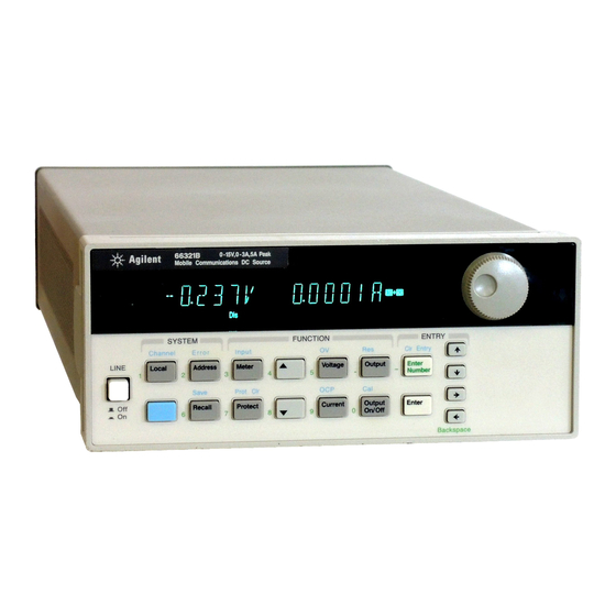
Quick Reference The Front Panel - At a Glance 14-character display Annunciators indicate Rotary control sets voltage, shows output measurements operating modes and status current, and menu parameters. and programmed values. conditions. to set the resolution; then adjust the value with the knob. 66319D DUAL OUTPUT Mobile Communications DC Source... -
Page 10: The Rear Panel - At A Glance
FOR CONTINUED FIRE PROTECTION, USE SPECIFIED LINE FUSE Output 2 connector Output 1 connector. Power cord (Agilent 66319B/D only). Connector plug is removable. connector (IEC 320) IMPORTANT: Install this connector with Connector plug is removable. its supplied sense jumpers before applying power to the unit. -
Page 11: Front Panel Number Entry
Quick Reference - 1 Front Panel Number Entry Enter numbers from the front panel using one the following methods: Use the arrow keys and knob to change voltage or current settings NOTE: The output must be ON to see the displayed values change in Meter mode. With the output enabled, this method changes the output voltage or current immediately. -
Page 12: Front Panel Annunciators
1 - Quick Reference Front Panel Annunciators Output 1 or output 2 is operating in constant voltage mode. Output 1 or output 2 is operating in constant current mode. Output 1 or output 2 is unregulated. The output is OFF. Press the Output On/Off key to turn the output on. The over-current protection state is ON. -
Page 13: Front Panel Menus - At A Glance
Sets the buffer size for a front panel measurement Shift CAL ON Accesses calibration menu (See Appendix B) to select parameters (table shows factory defaults). to exit any menu. Meter Only valid for Agilent Model 66319B/D Only valid for Agilent Model 66321D/66319D... -
Page 14: Scpi Programming Commands - At A Glance
:PON :STATe RST | RCL0 [:SEQuence1| :TRANsient][:IMMediate] :PROTection :CLEar :SOURce BUS :DELay <n> :SEQuence1 :DEFine TRANsient :RELay :MODE DD | HD | DH | HH :SEQuence2 :DEFine ACQuire :RI :MODE LATCHing | LIVE | OFF Only valid for Agilent 66319B/D Only valid for 66321D/66319D... -
Page 15: General Information
This manual describes the operation of the Agilent Model 66321B/D Mobile Communications and the Agilent Model 66319B/D Dual Output DC Source. Agilent Models 66321D and 66319D have an additional DVM measurement input on the rear panel. Unless otherwise noted, all models will be referred to by the description "dc source"... -
Page 16: Safety Considerations
Lock-link kit (p/n 5061-9694) and Flange kit (p/n 5062-3974) Rack mount kit for one unit (p/n 5062-3972) Solid-state relays to connect and disconnect the output of the dc source (Agilent 66319B/D only). Provides the ability to either Hot-switch or Dry-switch the solid state relays. -
Page 17: Description And Model Differences
Agilent 66319B The Agilent 66319B Mobile Communications DC Source includes all of the capabilities of the Agilent 66321B with the addition of a second, electrically-isolated output. Figure 2-2 describes output characteristic of this second output, which is primarily used to provide voltage or current for a charger input on the device under test. -
Page 18: Front Panel Controls
Non-volatile state storage and recall with SCPI command language. ♦ User-configurable power-on/reset settings (see Appendix B). Table 2-3. Agilent Model Differences Item 66321B 66321D 66319B 66319D 66311B/D 66309B/D 0 - 1 A range current measurements (output 1) 0 - 20 mA range current... -
Page 19: Output 1 Characteristic
General Information - 2 Output 1 Characteristic The dc source's main output (output 1) characteristic is shown in the following figure. The main output of the dc source may be adjusted to any value within the boundaries shown. Output Voltage ISET -1.2A VSET... -
Page 20: Output 2 Characteristic
Output 2 Characteristic As shown in the following figure, Agilent 66319B/D units have a second output rated at 12 V and 1.5A. The second output has all of the primary programmable features as the main output, with the exception of the waveform measurement capability, the open sense lead detect capability, overvoltage protection, and low current range. -
Page 21: Option 521 Description (Agilent 66319B/D Only)
General Information - 2 Option 521 Description (Agilent 66319B/D only) Option 521 consists of the following enhancements to the output capabilities of Agilent models 66319B/66319D: ♦ Solid-state relays to connect and disconnect the output of the dc source. The relays are available on the output and sense terminals of outputs 1 and 2. When the solid state relays are open, the output impedance is effectively raised to about 500k ohms for output 1, and about 200k ohms for output 2. -
Page 23: Installation
Installation Installation and Operation Checklist Check the Output Compensation # Check that the output compensation of the dc source is appropriate for your application. Refer to “Output Compensation” in this chapter. HRemote mode provides the best transient response and can be used with phones having input capacitances from 5µF to 12000µF. -
Page 24: Inspection
0360-2604 5-terminal output plug for connecting load and sense connector leads. This connector installs in the back of the unit. 1252-8670 3-terminal plug for DVM connections (66319B/D) connector Sense jumpers 8120-8821 Jumpers that insert into output connector for local sensing. Connect +s to +, and −s to −. -
Page 25: Location
Installation - 3 Location Figure 3-1 gives the dimensions of your dc source. The dc source must be installed in a location that allows sufficient space at the sides and back of the unit for adequate air circulation (see Bench Operation). -
Page 26: Input Connections
Output 2 Agilent 66319B/D units have a second output connector (output 2). It has the same configuration as the main output connector. It has a termination for the + and − output, the + and − sense terminals, and an earth ground terminal. -
Page 27: Remote Sense Connections
Installation - 3 Voltage Drops and Lead Resistance To optimize the performance and transient response in your test system, please observe the following guidelines: ♦ Twist the load leads together and keep them short. The shorter the leads, the better the performance. ♦... - Page 28 3 - Installation OUTPUT 1/OUTPUT 2 CONNECTOR TWIST LEADS TWIST PAIR LOAD WIRE RESISTANCE Figure 3-2. Remote Sense Connections Connect the remote sense leads only to the remote sense connections at the output connector and at the location on the test fixture where you want to sense the output voltage. There must be not be any continuity from the sense leads to earth ground or from the sense leads to the output leads other than at the test fixture.
-
Page 29: Load Regulation And Voltage Drop In The Remote Sense Leads
Installation - 3 Figure 3-4 shows how to connect remote sense leads when using a removable test fixture. Note that in this configuration, the wires in the part of the test fixture where the phone is located must be less than 50 cm (20 inches) in length. -
Page 30: Maintaining Stability While Remote Sensing
3 - Installation . ∆V can be further minimized Minimizing the load lead resistance reduces voltage drops V and V ) as much as possible. In situation where ∆V by decreasing the resistance of the sense leads (R and R cannot be minimized any further, it may be compensated by programming a negative output resistance as previously discussed. -
Page 31: Local Sensing
Installation - 3 The default setting for the open sense lead protection circuit is disabled or OFF. This is because applications that apply an external voltage to the output or that use external disconnect relays may interfere with the operation of the open sense detect circuit. If you are using external voltages or relays, you can enable the open sense detect at the beginning of the test procedure. - Page 32 3 - Installation Refer to the previous discussion under "Remote Sense Connections" and "Local Sensing" for more information about remote and local sensing. Standard dc source units are shipped from the factory with the output compensation set to HRemote mode. This mode provides the fastest output response but requires an external capacitor for stable operation.
-
Page 33: Ovp Considerations
Installation - 3 OVP Considerations CAUTION: Disabling the overvoltage protection circuit may cause excessive output voltages, which can damage the phone under test. The dc source is shipped from the factory with its overvoltage protection (OVP) circuit enabled. This built-in overvoltage protection function is not programmable; it is set to automatically trip when the output voltage measured at the sense lead terminals exceeds the programmed voltage by two volts. -
Page 34: Dvm Connections
3 - Installation DVM Connections The DVM may be damaged if voltages at the input terminals exceed ±50 Vdc to ground. CAUTION: The DVM connector has three pins: plus, minus, and earth ground. The 3-pin connector is removable and accepts wires sizes from AWG 22 to AWG 14. Disconnect the mating plug by pulling it straight back. The DVM is designed as an auxiliary measurement input that can measure voltages on circuits that are powered by the main output (output 1). - Page 35 Installation - 3 Because the measurement circuits of the DVM are internally referenced to the minus terminal of the main output, you must observe the following restrictions in order to guarantee accurate DVM measurements (refer to figure 3-7). Test Fixture (for illustration only) Node # V Common Mode 36 V + V 24 V + V...
-
Page 36: External Protection And Trigger Input Connections
3 - Installation Measuring Circuits that are Floating with Respect to the Main Output In the example shown in figure 3-8, the common mode voltage between the DVM inputs and the minus terminal of the main output (output 1) includes an undefined floating voltage that may result in incorrect readings due to clipping by the internal DVM measurement circuits. - Page 37 Installation - 3 Table 3-3. 4-Pin Connector Configurations TRIGGER FAULT/INHIBIT DIGITAL I/O Not used FLT Output Output 0 Not used FLT Common Output 1 Trigger Input INH Input Input/Output 2 Trigger Common INH Common Common When functioning in Fault/Inhibit mode, the fault (FLT) output, also referred to as the DFI (discrete fault indicator) signal, is an open collector circuit that pulls the positive output low with respect to the negative (chassis-referenced) common.
-
Page 38: Digital I/O Connections
3 - Installation Digital I/O Connections As shown in Table 3-3 and Figure 3-10, the 4-pin connector can also be configured as a digital I/O port. Information on programming the digital I/O port is found in chapter 5 and under [SOURce:]DIGital:DATA and [SOURce:]DIGital:FUNCtion commands in chapter 8. -
Page 39: Turn-On Checkout
Turn-On Checkout Checkout Procedure Successful tests in this chapter provide a high degree of confidence that your unit is operating properly. For performance tests, see appendix B. NOTE: To perform the checkout procedure, you will need a wire for shorting the output terminals together. - Page 40 The next time the unit turns on it will be restored to the shorting wire from the the *RST or factory default state. output terminals. Only perform steps 19 to 29 if you are verifying an Agilent 66319B or 66319D unit. Procedure Display Explanation Turn the unit on.
-
Page 41: In Case Of Trouble
Turn-On Checkout - 4 Procedure Display Explanation Connect a jumper wire Shorts output 2 of the unit. across the + and - terminals of output 2. Press Output On/Off. 0.004V 1.520A The CC annunciator is on, indicating that output 2 is in constant current mode. -
Page 42: Runtime Error Messages
4 - Turn-On Checkout Runtime Error Messages Appendix C lists other error messages that may appear at runtime. Some of these messages will also appear on the front panel when the Prot key is pressed. To clear the error, you must remove the condition that caused the error and then press the Prot Clear key. -
Page 43: Front Panel Operation
Front Panel Operation Introduction Here is what you will find in this chapter: ♦ a complete description of the front panel controls ♦ front panel programming examples NOTE: The dc source must be in set to Local mode to use the front panel controls. Press the key on the front panel to put the unit in local mode. - Page 44 5 – Front Panel Operation 14-character vacuum fluorescent display for showing output measurements and Display programmed values. Annunciators light to indicate operating modes and status conditions: Annunciators CV The dc source output is in constant-voltage mode. CC The dc source output is in constant-current mode. Unr The dc source output is in an unregulated state.
-
Page 45: System Keys
Front Panel Operation - 5 System Keys Refer to the examples later in this chapter for more details on the use of these keys. SYSTEM Channel Error Local Address Save Recall Figure 5-2. System Keys Shift This is the blue, unlabeled key, which is also shown as in this guide. -
Page 46: Function Keys
5 – Front Panel Operation Function Keys Refer to the examples later in this chapter for more details on the use of these keys. FUNCTION Input Meter Output Voltage Prot Cir Current Protect Output On/Off Figure 5-3. Function Keys Immediate Action Keys Immediate action keys immediately execute their corresponding function when pressed. -
Page 47: Metering Keys
Front Panel Operation - 5 Metering Keys Metering keys control the metering functions of the dc source. As set from the factory, all front panel measurements from the main output (output 1), are calculated from a total of 2048 readings taken at a 46.8 microsecond sampling rate. -
Page 48: Output Control Keys
5 – Front Panel Operation Output Control Keys Output control keys control the output functions of the dc source. Voltage Press this key to access the voltage menu. Display Command Function VOLT <value> Sets the voltage of output 1 (the main output of all models) VOLT <value>... -
Page 49: Entry Keys
Front Panel Operation - 5 Entry Keys Refer to the examples later in this chapter for more details on the use of these keys. ENTRY Cir Entry Enter Number Enter Backspace Figure 5-4. Entry Keys # # # # & & & & These keys let you scroll through choices in a parameter list that apply to a specific command. -
Page 50: Examples Of Front Panel Programming
DVM measurement commands are identified by the "DVM" string segment. When accessed, DVM measurement functions are automatically active. Refer to example 3 for more information. Independently Control Output 1 and Output 2 on Agilent 66319B/D units Action Display On the Function keypad, press Output. - Page 51 Front Panel Operation - 5 Set the output voltage Action Display To enter an approximate value without using the voltage menu: On the Entry keypad, 7.003V 0.004A press " or ! to select the 1's digit in the voltage field. Then rotate the front panel RPG knob to obtain 7 V.
- Page 52 2. 3 - Setting the Output 2 Voltage and Current (Agilent 66319B/66319D only) This example shows you how to set the voltage and current for output 2. Selecting an output was discussed in the previous example.
-
Page 53: Querying And Clearing Output Protection And Errors
Front Panel Operation - 5 To make minor changes to an existing value, press Current. The procedure to change an individual digit is explained in step 3 under "Set the output 2 voltage." NOTE: To draw current pulses greater than 1.5 A and up to 2.5 A peak on output 2, set the output current limit higher than 1.5 amperes (1.52 amperes max). - Page 54 5 – Front Panel Operation 5 – Making Basic Front Panel Measurements As shipped from the factory, front panel measurements for the main output (output 1) are calculated from a total of 2048 readings taken at a 46.8 microsecond sampling rate. The unit alternates between voltage and current measurements.
- Page 55 The following figure illustrates the enhanced measurement capabilities of Agilent Models 66321B/D and 66319B/D for measuring output waveforms. These include peak (max), minimum, high level, and low level measurements as illustrated in the following figure. Rms and dc voltages are calculated from the number of points in the measurement window.
- Page 56 5 – Front Panel Operation Continue by pressing Shift, Input and ( until you obtain the POINT command. POINT 1024 Press & to select a different buffer size. The choices are: 1, 2, 4, 8, 16, 32, 64, 128, 256, 512, 1024, and 2048. Then press Enter. One reason to change the front panel time interval and data points is if the waveform being measured has a period shorter than 3 times the present front panel acquisition time.
-
Page 57: Setting The Gpib Address
Front Panel Operation - 5 8 - Programming Output Port Functions You can configure the output port to perform three different functions. In RIDFI mode, the port functions as a remote inhibit input with a discrete fault indicator output signal. In DIGIO mode, the port acts as a digital Input/Output device. -
Page 58: Storing And Recalling Instrument States
5 – Front Panel Operation 10 - Storing and Recalling Instrument States You can save up to 4 states (from location 0 to location 3) in non-volatile memory and recall them from the front panel. All programmable settings are saved. This capability is only available when the unit is set to the SCPI programming language. -
Page 59: Introduction To Programming
Introduction to Programming External References GPIB References The most important GPIB documents are your controller programming manuals - BASIC, GPIB Command Library for MS DOS, etc. Refer to these for all non-SCPI commands (for example: Local Lockout). The following are two formal documents concerning the GPIB interface: ♦... -
Page 60: Vxiplug&Play Power Products Instrument Drivers
VXIplug&play instrument drivers for Microsoft Windows 95 and Windows NT are now available on the Web at http://www.agilent.com/find/drivers. These instrument drivers provide a high-level programming interface to your Agilent Technologies instrument. VXIplug&play instrument drivers are an alternative to programming your instrument with SCPI command strings. Because the instrument driver's function calls work together on top of the VISA I/O library, a single instrument driver can be used with multiple application environments. -
Page 61: Gpib Capabilities Of The Dc Source
Introduction to Programming - 6 Accessing Online Help A comprehensive online programming reference is provided with the driver. It describes how to get started using the instrument driver with Agilent VEE, LabVIEW, and LabWindows. It includes complete descriptions of all function calls as well as example programs in C/C++ and Visual BASIC. To access the online help when you have chosen the default Vxipnp start folder, click on the Start button and select Programs | Vxipnp | Agxxxx Help (32-bit). -
Page 62: Types Of Scpi Commands
6 - Introduction to Programming Types of SCPI Commands SCPI has two types of commands, common and subsystem. ♦ Common commands generally are not related to specific operation but to controlling overall dc source functions, such as reset, status, and synchronization. All common commands consist of a three-letter mnemonic preceded by an asterisk: *RST *IDN? *SRE 8... -
Page 63: Types Of Scpi Messages
Introduction to Programming - 6 Moving Among Subsystems In order to combine commands from different subsystems, you need to be able to reset the header path to a null string within a message. You do this by beginning the command with a colon (:), which discards any previous header path. -
Page 64: Query Indicator
6 - Introduction to Programming Message Unit Data Keywords Query Indicator VOLT : LEV 20 PROT 21 ; : CURR? <NL> Keyword Separator Message Terminator Message Unit Separators Root Specifier Figure 6-2. Command Message Structure Headers Headers, also referred to as keywords, are instructions recognized by the dc source. Headers may be either in the long form or the short form. -
Page 65: Scpi Data Formats
Introduction to Programming - 6 SCPI Data Formats All data programmed to or returned from the dc source is ASCII. The data may be numerical or character string. Numerical Data Formats Symbol Response Formats Digits with an implied decimal point assumed at the right of the least-significant digit. <NR1>... -
Page 66: Scpi Command Completion
6 - Introduction to Programming SCPI Command Completion SCPI commands sent to the dc source are processed either sequentially or in parallel. Sequential commands finish execution before a subsequent command begins. Parallel commands allow other commands to begin executing while the parallel command is still executing. Commands that affect trigger actions are among the parallel commands. -
Page 67: Scpi Conformance Information
Introduction to Programming - 6 SCPI Conformance Information SCPI Conformed Commands The Agilent 66321B/D and 66319B/D conform to SCPI Version 1995.0. ABOR OUTP:PROT:DEL STAT:QUES:ENAB CAL:DATA OUT:PROT:STAT STAT:QUES:NTR CAL:STAT [SOUR]:CURR[:LEV][:IMM][:AMPL] STAT:QUES:PTR DISP[:WIND][:STAT] [SOUR]:CURR[:LEV]:TRIG[:AMPL] SYST:ERR? DISP[:WIND]:TEXT[:DATA] [SOUR]:CURR:PROT:STAT SYST:LANG INIT[:IMM]:SEQ | NAME [SOUR]:VOLT[:LEV][:IMM][:AMPL]... -
Page 69: Programming The Dc Source
To enable the output, use the command: OUTP ON Note that this command enables both outputs on Agilent 66319B/66319D units. Output Voltage The output voltage is controlled with the VOLTage command. To set the output voltage to 5 volts, use:... -
Page 70: Output Current
7 - Programming the DC Source Maximum Voltage The maximum output voltage that can be programmed can be queried with: VOLT? MAX Overvoltage Protection The dc source will turn off its output if the output voltage exceeds its programmed setting by two volts when measured at the + sense and −... -
Page 71: Triggering Output Changes
Programming the DC Source - 7 Triggering Output Changes The dc source has two independent trigger systems. One is used for synchronizing output changes, and the other is used for synchronizing measurements. This section describes the output trigger system. The measurement trigger system is described under "Triggering Measurements". -
Page 72: Generating Triggers
7 - Programming the DC Source Enabling the Output Trigger System When the dc source is turned on, the trigger subsystem is in the idle state. In this state, the trigger subsystem is disabled, ignoring all triggers. Sending the following commands at any time returns the trigger system to the idle state: ABOR *RST... -
Page 73: Making Basic Measurements
Programming the DC Source - 7 Making Basic Measurements All dc sources have excellent output voltage and current measurement capability. NOTE: There is only one measurement system in the dc source. Therefore, you can perform only one measurement function (voltage, current, or DVM) at a time. All measurements are performed by digitizing the instantaneous output voltage or current for a defined number of samples and sample interval, storing the results in a buffer, and then calculating the measured result. -
Page 74: Making Enhanced Measurements
MEAS:CURR2? Making Enhanced Measurements Agilent Models 66321B/D and 66319B/D have the ability to make several types of voltage or current waveform measurements. These expanded measurement capabilities are particularly useful for loads that draw current in pulses. The SCPI language MEASure and FETCh queries are used to return the various... -
Page 75: Current Ranges And Measurement Detector
Programming the DC Source - 7 There are two ways to make enhanced measurements: ♦ Use the MEASure queries to immediately start acquiring new voltage or current data, and return measurement calculations from this data as soon as the buffer is full. This is the easiest way to make measurements, since it requires no explicit trigger programming. - Page 76 7 - Programming the DC Source Pulse Measurements After pulse data has been acquired, use FETCh queries to return measurement data in the shortest time. FETCh queries do not trigger the acquisition of new measurement data, but return different calculations from the data that was acquired.
-
Page 77: Making Dvm Measurements
Programming the DC Source - 7 Returning All Measurement Data From the Data Buffer The MEASure:ARRay and FETCh:ARRay queries return all data values of the instantaneous voltage or current buffer. No weighting function is applied, returning only raw data from the buffer. The commands are: MEAS:ARR:CURR? MEAS:ARR:VOLT? -
Page 78: Triggered Measurements
7 - Programming the DC Source Triggered Measurements Use the measurement trigger system to synchronize the acquisition of measurements with either a BUS or internal trigger. You can trigger voltage and current measurements on the main output (output 1) and on the DVM. -
Page 79: Enabling The Measurement Trigger System
Programming the DC Source - 7 Enabling the Measurement Trigger System When the dc source is turned on, the trigger system is in the idle state. In this state, the trigger system is disabled and it ignores all triggers. Sending the following commands at any time returns the trigger system to the idle state: ABORt *RST... -
Page 80: Generating Measurement Triggers
7 - Programming the DC Source Generating Measurement Triggers Single Triggers After you specify the appropriate trigger source and sensing function, generate triggers as follows: GPIB Triggers Send one of the following commands over the GPIB: TRIG:IMM (not affected by the trigger source setting) *TRG an IEEE-488 Group Execute Trigger bus command To trigger off of the output signal, you must specify the output level that... - Page 81 Programming the DC Source - 7 One way to wait for results without tying up the computer is to use the SCPI command completion commands. For example, you can send the *OPC command after INITialize, then occasionally poll the OPC status bit in the standard event status register for status completion while doing other tasks. You can also set up an SRQ condition on the OPC status bit going true and do other tasks until the SRQ interrupts.
-
Page 82: Programming The Status Registers
7 - Programming the DC Source Pre-trigger and Post-trigger Data Acquisition The measurement system lets you capture data before, after, or at the trigger signal. When a measurement is initiated, the dc source continuously samples the instantaneous signal level of the sensing function. As shown in figure 7-7, you can move the block of data being read into the acquisition buffer with reference to the acquisition trigger. - Page 83 Programming the DC Source - 7 Power-On Conditions Refer to the *RST command description in chapter 8 for the power-on conditions of the status registers. QUESTIONABLE STATUS CONDITION PTR/NTR EVENT ENABLE N.U. N.U. LOGICAL UNR2 1024 1024 1024 1024 OUTPut:DFI N.U.
- Page 84 7 - Programming the DC Source Table 7-1. Bit Configurations of Status Registers Signal Meaning Operation Status Group The dc source is computing new calibration constants The dc source is waiting for a trigger The dc source is in constant voltage mode Output 2 is operating in constant voltage mode The dc source is in constant current mode The dc source is in negative constant current mode...
-
Page 85: Questionable Status Group
Programming the DC Source - 7 Questionable Status Group The Questionable Status registers record signals that indicate abnormal operation of the dc source. As shown in figure 7-7, the group consists of the same type of registers as the Status Operation group. The outputs of the Questionable Status group are logically-ORed into the QUEStionable summary bit (3) of the Status Byte register. -
Page 86: Determining The Cause Of A Service Interrupt
7 - Programming the DC Source The MSS Bit This is a real-time (unlatched) summary of all Status Byte register bits that are enabled by the Service Request Enable register. MSS is set whenever the dc source has one or more reasons for requesting service. -
Page 87: Inhibit/Fault Indicator
Programming the DC Source - 7 Step 1 Program the Operation Status PTR register to allow a positive transition at bit 10 to be latched into the Operation Status Event register, and allow the latched event to be summed into the Operation summary bit. Use: STAT:OPER:PTR 1024;ENAB 1024 Step 2 Program the Questionable Status PTR register to allow a positive transition at bits 0,... - Page 88 7 - Programming the DC Source Discrete Fault Indicator (DFI) The discrete fault indicator is an open-collector logic signal connected to the rear panel FLT connection that can be used to signal external devices when a fault condition is detected. To select the internal fault source that drives this signal, use: OUTPut:DFI:SOURce QUEStionable | OPERation | ESB | RQS | OFF To enable or disable the DFI output, use:...
-
Page 89: Language Dictionary
Language Dictionary Introduction This section gives the syntax and parameters for all the IEEE 488.2 SCPI commands and the Common commands used by the dc source. It is assumed that you are familiar with the material in chapter 6, which explains the terms, symbols, and syntactical structures used here and gives an introduction to programming. - Page 90 8 – Language Dictionary Table 8-1. Subsystem Commands Syntax ABORt Resets the trigger system to the Idle state CALibrate :CURRent [:SOURce] [:DC] [:POSitive] Calibrate positive output current and high current measurement range :MEASure [:DC] Calibrate middle current measurement range :LOWRange Calibrate low current measurement range Calibrate ac current measurement circuits :CURRent2...
- Page 91 Language Dictionary - 8 Table 8-1. Subsystem Commands Syntax (continued) Returns DVM dc voltage measurement :DVM [:DC]? :ACDC? Returns DVM rms voltage measurement :VOLTage [:DC]? Returns dc voltage Returns the total rms voltage (ac+dc) :ACDC? Returns the HIGH level of a voltage pulse :HIGH? :LOW? Returns the LOW level of a voltage pulse...
- Page 92 8 – Language Dictionary Table 8-1. Subsystem Commands Syntax (continued) :PROTection [:LEVel] <n> Sets the programmable output voltage limit Enables/disables automatic overvoltage protection tracking :STATe <bool> VOLTage2 [:LEVel] Sets the output2 voltage level [:IMMediate][:AMPLitude] <n> :TRIGgered [:AMPLitude] <n> Sets the triggered output2 voltage level STATus Presets all enable and transition registers to power-on :PRESet...
-
Page 93: Common Commands
Language Dictionary - 8 Common Commands Common commands begin with an * and consist of three letters (command) or three letters and a ? (query). They are defined by the IEEE 488.2 standard to perform common interface functions. Common commands and queries are categorized under System, Status, or Trigger functions and are listed at the end of the chapter. -
Page 94: Calibration Commands
! enable calibration Examples CAL:STAT 1, ! start current calibration CAL:CURR, Related Commands CAL:CURR:NEG, CAL:LEV, CAL:DATA CALibrate:CURRent2 Agilent 66319B/D only This command initiates the current calibration of output 2. Command Syntax CALibrate:CURRent2 Parameters None Examples CAL:CURR2 Related Commands CAL:CURR:NEG, CAL:LEV, CAL:DATA CALibrate:CURRent:MEASure:R3 This command initiates the calibration of the middle-range current measurement circuit. - Page 95 Language Dictionary - 8 CALibrate:CURRent:MEASure:AC This command initiates the calibration of the high bandwidth (ac) measurement circuit. Command Syntax CALibrate:CURRent:MEASure:AC Parameters None Examples CAL:CURR:MEAS:AC CALibrate:DATA This command enters a calibration value that you obtain by reading an external meter. You must first select a calibration level (with CALibrate:LEVel) for the value being entered.
- Page 96 This command initiates the calibration of the output voltage and the voltage readback circuit. Command Syntax CALibrate:VOLTage[:DC] Parameters None Examples CAL:VOLT CAL:VOLT:DC CALibrate:VOLTage2 Agilent 66319B/D only This command initiates the voltage calibration of output 2. Command Syntax CALibrate:VOLTage2 Parameters None Examples CAL:VOLT2...
-
Page 97: Display Commands
Returned Parameters <NR1> 0 or 1 DISPlay:CHANnel Agilent 66319B/D only Selects the output channel that will be displayed on the front panel. When output 1 is selected, a small "1" appears in the left-most digit. . When output 2 is selected, a small "2" appears in the left-most digit. -
Page 98: Measurement Commands
8 – Language Dictionary Measurement Commands Measurement commands consist of format, measure, and sense commands. Format commands specify the data formatting of all array queries. You can specify the data type, type length, and byte order. Measure commands measure the output voltage or current. Measurements are performed by digitizing the instantaneous output voltage or current for a specified number of samples, storing the results in a buffer, and calculating the measured result. - Page 99 Language Dictionary - 8 FORMat:BORDer This command selects whether the binary data is transferred in normal or swapped byte order. When NORMal is selected, the first byte sent is the sign bit and seven most significant bits of the exponent, and the last byte sent is the least significant byte of the mantissa.
- Page 100 Related Commands MEAS:VOLT? SENS:CURR:RANG MEASure:CURRent2? Agilent 66319B/D only This query measures the output current at the auxiliary output. Output 2 measurements are calculated from a total of 2048 readings taken at a 15.6 microsecond sampling rate. These parameters are fixed.
- Page 101 Language Dictionary - 8 MEASure:CURRent:HIGH? FETCh:CURRent:HIGH? These queries return the High level current of a current pulse waveform. The instrument first measures the minimum and maximum data points of the pulse waveform. It then generates a histogram of the pulse waveform using 16 bins between the maximum and minimum data points.
- Page 102 8 – Language Dictionary MEASure:CURRent:MINimum? FETCh:CURRent:MINimum? These queries return the minimum output current. Query Syntax MEASure[:SCALar]:CURRent:MINimum? FETCh[:SCALar]:CURRent:MINimum? Parameters None Examples MEAS:CURR:MIN? FETC:CURR:MIN? Returned Parameters <NR3> Related Commands MEAS:CURR:MAX? MEASure:DVM? FETCh:DVM? Agilent 66321D/66319D only These queries measure dc voltage. Query Syntax MEASure[:SCALar]:DVM[:DC]? FETCh[:SCALar]:DVM[:DC]? Parameters None Examples MEAS:DVM:DC?
- Page 103 Language Dictionary - 8 MEASure:VOLTage2 Agilent 66319B/D only This query measures the output voltage at the auxiliary output. Output 2 measurements are calculated from a total of 2048 readings taken at a 15.6 microsecond sampling rate. These parameters are fixed.
- Page 104 8 – Language Dictionary MEASure:VOLTage:LOW? FETCh:VOLTage:LOW? These queries return the Low level voltage of a voltage pulse waveform. The instrument first measures the minimum and maximum data points of the pulse waveform. It then generates a histogram of the pulse waveform using 16 bins between the maximum and minimum data points.
- Page 105 Language Dictionary - 8 SENSe:CURRent:DETector This command lets you select the type of detector used for output current measurements. Two choices for detecting current measurements are available: ACDC This is the preferred choice for all dynamic current measurements. When ACDC is selected, the measured output current includes the current that flows in the instrument's output capacitor.
- Page 106 8 – Language Dictionary SENSe:LEAD:STATus? This query returns the status of the open sense detection circuit. The query must be performed with the output disabled. Any external source such as an external capacitor must be discharged. The following status code is returned: Value Description Value...
- Page 107 Language Dictionary - 8 SENSe:SWEep:POINts This command defines the number of points in a measurement. Command Syntax SENSe:SWEep:POINts<NRf+> Parameters 1 through 4096 *RST Value 2048 Examples SENS:SWE:POIN 1024 Query Syntax SENSe:SWEep:POINts? Returned Parameters <NR3> Related Commands SENS:SWE:TINT SENS:SWE:OFFS MEAS:ARR SENSe:SWEep:TINTerval This command defines the time period between samples.
-
Page 108: Output Commands
This command enables or disables the dc source output. If outputs 1 and 2 are coupled, it affects both the main output and output 2 on Agilent 66319B/D units. If the outputs are not coupled and no output channel is specified, the command applies to the main output. The state of a disabled output is a condition of zero output voltage and a model-dependent minimum source current (see *RST). - Page 109 Language Dictionary - 8 OUTPut[1 | 2]:RELay:MODE Agilent 66319B/66319D with Option 521 only Specifies one of the relay modes (DD, DH, HD, or HH). The output must be turned off before any programmed mode settings take effect. Relay settings cannot be coupled; they must be set separately for each output.
- Page 110 8 – Language Dictionary Command Syntax OUTPut:COMPensation:MODE <setting> Parameters LLOCAL | LREMOTE | HLOCAL | HREMOTE *RST Value HREMOTE Examples OUTP:COMP:MODE HREMOTE Query Syntax OUTPput:COMPensation:MODE? Returned Parameters <CRD> Backward Compatibility OUTP:TYPE[:CAPacitance] (LOW mode corresponds to (Agilent 66311B/D, 66309B/D) LLocal; HIGH mode corresponds to HRemote) OUTPut:DFI This command enables or disables the discrete fault indicator (DFI) output from the dc source.
- Page 111 Language Dictionary - 8 OUTPut:PROTection:CLEar This command clears the latch that disables the output when an overvoltage, overcurrent, overtemperature, or remote inhibit status condition is detected. All conditions that generate the fault must be removed before the latch can be cleared. The output is then restored to the state it was in before the fault condition occurred.
- Page 112 CURRENT:LEVEL 200 MA Query Syntax [SOURce:]CURRent[:LEVel][:IMMediate][:AMPLitude]? Returned Parameters <NR3> Related Commands CURR:TRIG [SOURce:]CURRent2 Agilent 66319B/66319D only This command sets the output current level of the auxiliary output. Command Syntax [SOURce:]CURRent2[:LEVel][:IMMediate][:AMPLitude] <NRf+> Parameters see Table A-3 Default Suffix A (amperes) *RST Value 10% of MAX...
- Page 113 Returned Parameters <NR3> [SOURce:]CURRent2:TRIGger Agilent 66319B/66319D only This command sets the triggered current level of the auxiliary output. The triggered level is a stored value that is transferred to the output when a trigger occurs. In order for a trigger to occur, the trigger subsystem must be initiated (see the INITiate command).
- Page 114 8 – Language Dictionary Command Syntax [SOURce:]DIGital:DATA[:VALue] <NRf> Parameters 0 to 7 *RST Value 0 Examples DIG:DATA 7 Query Syntax [SOURce:]DIGital:DATA? Returned Parameters <NR1> [SOURce:]DIGital:FUNCtion Configures the 4-pin control port. The configuration setting is saved in non-volatile memory. Configures the port for Remote Inhibit/Discrete Fault Interrupt operation RIDFi Configures the port for Digital input/output operation (see DIG:DATA) DIGio...
- Page 115 !set output voltage to 2.5V Query Syntax [SOURce:]VOLTage[:LEVel][:IMMediate][:AMPLitude]? Returned Parameters <NR3> Related Commands VOLT:TRIG VOLT:PROT [SOURce:]VOLTage2 Agilent 66319B/66319D only This command sets the output voltage level of the auxiliary output. Command Syntax [SOURce:]VOLTage2[:LEVel][:IMMediate][:AMPLitude]<NRf+> Parameters see Table A-3 Default Suffix V (volts) *RST Value 0 Examples VOLT2 500mV !set output2 voltage to 0.5V...
- Page 116 VOLT:PROT [SOURce:]VOLTage2:TRIGger Agilent 66319B/66319D only This command sets the triggered voltage level of the auxiliary output. The triggered level is a stored value that is transferred to the output when a trigger occurs. In order for a trigger to occur, the trigger subsystem must be initiated (see the INITiate command).
-
Page 117: Status Commands
WTG = The dc source is waiting for a trigger. CV = The dc source is operating in constant voltage mode. CV2 = Output 2 is operating in constant voltage mode. (Agilent 66319B/D only) CC+ = The dc source is operating in constant current mode. - Page 118 8 – Language Dictionary STATus:OPERation:ENABle This command and its query set and read the value of the Operational Enable register. This register is a mask for enabling specific bits from the Operation Event register to set the operation summary bit (OPER) of the Status Byte register.
- Page 119 UNR2 = output 2 is unregulated (Agilent 66319B/D only) RI = remote inhibit is active UNR = the output is unregulated OC2 = output 2 overcurrent protection has tripped (Agilent 66319B/D only) Meas Ovld = measurement overload STATus:QUEStionable:CONDition? This query returns the value of the Questionable Condition register. That is a read-only register, which holds the real-time (unlatched) questionable status of the dc source.
- Page 120 8 – Language Dictionary STATus:QUEStionable:NTR STATus:QUEStionable:PTR These commands allow you to set or read the value of the Questionable NTR (Negative-Transition) and PTR (Positive-Transition) registers. These registers serve as polarity filters between the Questionable Enable and Questionable Event registers to cause the following actions: $ When a bit of the Questionable NTR register is set to 1, then a 1-to-0 transition of the corresponding bit of the Questionable Condition register causes that bit in the Questionable Event register to be set.
-
Page 121: System Commands
Language Dictionary - 8 System Commands System commands control system functions that are not directly related to output control or measurement functions. SYSTem:ERRor? This query returns the next error number followed by its corresponding error message string from the remote programming error queue. The queue is a FIFO (first-in, first-out) buffer that stores errors as they occur. -
Page 122: Trigger Commands
8 – Language Dictionary Trigger Commands Trigger commands consist of trigger and initiate commands. They are used to generate output transients and measurement triggers. Initiate commands initialize the trigger system. Trigger commands control the remote triggering of the dc source. Trigger commands (and Initate commands) are referenced either by name or by number. The correspondence between names and numbers is: Sequence Number Sequence Name... - Page 123 Language Dictionary - 8 INITiate:CONTinuous:SEQuence1 INITiate:CONTinuous:NAME TRANsient These commands control the output transient trigger system. 1 or ON continuously initiates the output trigger system.. turns off continuous triggering. In this state, the output trigger system must be initiated 0 or OFF for each trigger using INITiate:SEQuence.
- Page 124 8 – Language Dictionary TRIGger:SEQuence2 TRIGger:ACQuire These commands generate a BUS trigger for the measurement trigger system. When the measurement trigger system is enabled, the measurement trigger causes the dc source to measure either the voltage or current on the main output or the DVM inputs and store the results in a buffer. The SENSe:FUNCtion command selects the signal that will be measured.
- Page 125 Language Dictionary - 8 TRIGger:SEQuence2:COUNt:VOLTage TRIGger:ACQuire:COUNt:VOLTage This command sets up a successive number of triggers for measuring voltage data. With this command, the trigger system needs to be initialized only once at the start of the acquisition period. After each completed measurement, the instrument waits for the next valid trigger condition to start another measurement.
- Page 126 8 – Language Dictionary TRIGger:SEQuence2:HYSTeresis:DVM TRIGger:ACQuire:HYSTeresis:DVM Agilent 66321D/66319D only This command defines a band around the trigger level through which the input signal must pass before a DVM measurement can occur. The band limit above and below the trigger level is one half of the hysteresis value added to or subtracted from the trigger level.
- Page 127 Language Dictionary - 8 TRIGger:SEQuence2:LEVel:CURRent TRIGger:ACQuire:LEVel:CURRent This command sets the trigger level for internally triggered current measurements. A positive current trigger occurs when the current level changes from a value less than the lower hysteresis band limit to a value greater than the upper hysteresis band limit. Similarly, a negative current trigger occurs when the current level changes from a value greater than the upper hysteresis band limit to a value less than the lower hysteresis band limit.
- Page 128 8 – Language Dictionary TRIGger:SEQuence2:LEVel:VOLTage TRIGger:ACQuire:LEVel:VOLTage This command sets the trigger level for internally triggered voltage measurements. A positive voltage trigger occurs when the voltage level changes from a value less than the lower hysteresis band limit to a value greater than the upper hysteresis band limit. Similarly, a negative voltage trigger occurs when the voltage level changes from a value greater than the upper hysteresis band limit to a value less than the lower hysteresis band limit.
- Page 129 Language Dictionary - 8 Command Syntax TRIGger:SEQuence2:SLOPe:DVM<slope> TRIGger:ACQuire:SLOPe:DVM<slope> Parameters EITHer | POSitive | NEGative *RST Value POSitive Examples TRIG:SEQ2:SLOP:DVM POS TRIG:ACQ:SLOP:DVM EITH Query Syntax TRIGger:SEQuence2:SLOPe:DVM? TRIGger:ACQuire:SLOPe:DVM? Returned Parameters <CRD> Related Commands TRIG:SEQ2:LEV:DVM TRIGger:SEQuence2:SLOPe:VOLTage TRIGger:ACQuire:SLOPe:VOLTage This command sets the slope of an internally triggered voltage measurement. triggering occurs on the rising edge.
-
Page 130: Common Commands
8 – Language Dictionary TRIGger:SEQuence1:DEFine TRIGger:SEQuence2:DEFine These commands define the names that are aliased to trigger sequences 1 and 2. The command accepts only ACQuire for sequence 2 and TRANsient for sequence 1 as predefined names. The query allows the user to query the instrument names aliased to sequences 1 and 2. - Page 131 <A>.xx.xx Revision levels of firmware. Example AGILENT TECHNOLOGIES,66321B,0,A.00.01 *OPC This command causes the instrument to set the OPC bit (bit 0) of the Standard Event Status register when the dc source has completed all pending operations. (See *ESE for the bit configuration of the Standard Event Status register.) Pending operations are complete when:...
- Page 132 8 – Language Dictionary *OPC does not prevent processing of subsequent commands, but bit 0 will not be set until all pending operations are completed. *OPC? causes the instrument to place an ASCII "1" in the Output Queue when all pending operations are completed.
- Page 133 Language Dictionary - 8 *RCL This command restores the dc source to a state that was previously stored in memory with the *SAV command to the specified location. All states are recalled with the following exceptions: $ the trigger system is set to the Idle state by an implied ABORt command (this cancels any uncompleted trigger actions) $ the calibration function is disabled by setting CAL:STATe to OFF NOTE:...
- Page 134 8 – Language Dictionary *SAV This command stores the present state of the dc source to the specified location in non-volatile memory. Up to 4 states can be stored. If a particular state is desired at power-on, it should be stored in location 0. It will then be automatically recalled at power turn-on if OUTPut:PON:STATe is set to RCL0.
- Page 135 Language Dictionary - 8 A serial poll also returns the value of the Status Byte register, except that bit 6 returns Request for Service (RQS) instead of Master Status Summary (MSS). A serial poll clears RQS, but not MSS. When MSS is set, it indicates that the dc source has one or more reasons for requesting service.
-
Page 137: A - Specifications
0μF to 12,000μF. Sensing is at the rear terminals of the power supply after a 30- minute warm-up period. Sense terminals are externally jumpered to their respective output terminals. Table A-1. Performance Specifications Parameter Agilent 66321B/D; Agilent 66319B/D Agilent 66319B/D output 2 only output 1 only Output Ratings Voltage: 0 –... -
Page 138: Supplemental Characteristics
Table A-2 lists the supplemental characteristics, which are not warranted but are descriptions of typical performance determined either by design or type testing. Table A-2. Supplemental Characteristics Parameter Agilent 66321B/D; Agilent 66319B/D Agilent 66319B/D output 2 only output 1 only Voltage: 0 –... - Page 139 Specifications - A Table A-2. Supplemental Characteristics (continued) Parameter Agilent 66321B/D; Agilent 66319B/D Agilent 66319B/D output 2 only output 1 only Typical Transient Voltage With short load leads: 30mV w/6µF load cap Undershoot Values (< 1 meter) 25mV w/20µF load cap...
- Page 140 To accept 10 Vrms sinewave input, the common mode voltage with respect to the negative terminal of output 1 must be 10 Vdc. This is required to "center" the DVM in its common mode range. Table A-4. Agilent 66319B/D Option 521 Characteristics Output Impedance...
-
Page 141: B - Performance, Calibration, And Configuration
If the dc source fails any of the tests or if abnormal test results are obtained, return the unit to an Agilent Technologies repair facility. This appendix also includes calibration procedures for the Agilent 66319B/D, 66321B/D Mobile Communications DC Sources. Instructions are given for performing the procedures either from the front panel or from a controller over the GPIB. -
Page 142: Measurement Techniques
B - Performance, Calibration, and Configuration DC Power Supply 8V @ 5A (for current sink verification/calibration) Agilent 6611C, 6631B 25 V source (for DVM verification/calibration) 6631C, or 6633B GPIB Controller Full GPIB capabilities (only required if you are HP Series 200/300 or calibrating the unit over the GPIB) equivalent Oscilloscope... -
Page 143: Performance Tests
Table B-2. Programming and Output Values Agilent Model Full scale Vmax Full Scale Imax Isink Voltage Current 66321B/D 15.356 3.0712 - 2A 22.0 66319B/D output 1 15.356 3.0712 - 2A 22.0 66319B/D output 2 12.25 1.52 N.A. N.A. -
Page 144: Constant Voltage (Cv) Tests
B - Performance, Calibration, and Configuration Constant Voltage (CV) Tests CV Setup If more than one meter or if a meter and an oscilloscope are used, connect each to the terminals by a separate pair of leads to avoid mutual coupling effects. For constant voltage dc tests, connect only to +S and -S, since the unit regulates the output voltage that appears between +S and -S, and not between the (+) and (-) output terminals. - Page 145 Performance, Calibration, and Configuration - B CV Source Effect (performance) This test measures the change in output voltage that results from a change in ac line voltage from the minimum to maximum value within the line voltage specifications. a. Turn off the dc source and connect the ac power line through a variable voltage transformer. b.
-
Page 146: Constant Current (Cc) Tests
B - Performance, Calibration, and Configuration c. Set the load to the Constant Current mode. For output 1, program the load current to 0.1A. For output 2, program the load current to 0.75A. d. Set the electronic load's transient generator frequency to 100 Hz and its duty cycle to 50%. e. - Page 147 Performance, Calibration, and Configuration - B 1A Range Current Readback Accuracy (performance, calibration) This test verifies the readback accuracy of the 1 ampere current range. a. Turn off the dc source and connect the current monitoring resistor across the dc source output and the DVM across the resistor as in Figure B-1b.
- Page 148 B - Performance, Calibration, and Configuration - 3A Range Current Sink Operation (performance, calibration) This test verifies current sink operation and readback of the –3A range. a. Turn off the dc source and connect the current monitoring resistor across the output and the DMM across the resistor as shown in Figure B-1b.
- Page 149 Performance, Calibration, and Configuration - B c. Adjust the load in the CV mode for the UUT full scale voltage in Table B-2 as indicated on the front panel display. Check that the CC annunciator of the UUT is on. If it is not, adjust the load so that the output voltage drops slightly.
-
Page 150: Resistance Tests
B - Performance, Calibration, and Configuration d. The output current should be at the full scale rating with the CC annunciator on. e. Divide the reading on the rms voltmeter by the current monitor resistance to obtain rms current. It should not exceed the values listed in the performance test record card under CC Noise (RMS). -
Page 151: Dvm Tests
Performance, Calibration, and Configuration - B DVM Tests DVM Measurement Accuracy (calibration) This test verifies the DVM measurement accuracy. a. Turn off the dc source and connect the external DMM and the external power supply to the DVM inputs as shown in figure B-1e. Connect only the negative output lead of output 1 to the DVM inputs. -
Page 152: Performance Test Record Form
B - Performance, Calibration, and Configuration Performance Test Record Form Model Agilent 66321B/D Report No ______________ Date __________________ Model Agilent 66319B/D Output 1 Test Description Minimum Results Maximum Specification Specification CONSTANT VOLTAGE TESTS Voltage Programming and Readback − 10 mV... - Page 153 Performance, Calibration, and Configuration - B Model 66319B/D Output 2 Report No _______________ Date __________________ Test Description Minimum Results Maximum Specification Specification CONSTANT VOLTAGE TESTS Voltage Programming and Readback − 40 mV Output 2 Low Voltage @ 0 V __________ + 40 mV Vout2 −...
-
Page 154: Performing The Calibration Procedure
B - Performance, Calibration, and Configuration Performing the Calibration Procedure NOTE: The calibration procedure can only be performed from the front panel or using the SCPI language commands. Table B-1 lists the equipment required for calibration. Figure B-1 shows the test setup. You do not have to do a complete calibration each time. -
Page 155: Front Panel Calibration Procedure
Press Shift Cal, scroll to CAL DATA, press Enter Number, and enter the CAL:DATA 0.00 second voltage value displayed on the DMM. Press Enter. Agilent 66319B/D Output 2 Voltage Programming and Measurement Calibration Action Display Connect the external DMM (in voltage mode) directly to output 2. - Page 156 B - Performance, Calibration, and Configuration Output 1 Current Programming and 3A-Range Measurement Calibration NOTE: When performing a 3A-Range current calibration, you must also calibrate the 1A range, the 0.02A range, and the ac current measurement. Action Display Connect the appropriate current monitor to the output terminals of output 1. Connect the DMM (in voltage mode) across the current shunt.
- Page 157 CAL:CURR:MEAS AC Wait for the dc source to compute the ac current calibration constant. The display returns to Meter mode when the calculation is complete. Agilent 66319B/D Output 2 Current Programming Measurement Calibration Action Display Connect the appropriate current monitor to the output terminals of output 2.
-
Page 158: Calibration Error Messages
B - Performance, Calibration, and Configuration Agilent 66321D, 66319D DVM Calibration Action Display Connect the DVM inputs directly to output 1. Connect the external DMM to the DVM inputs as shown in figure B-1e. Do not connect the Agilent 3478 DMM. -
Page 159: Performing The Configuration Procedure
Performance, Calibration, and Configuration - B Changing the Calibration Password The factory default password is 0. You can change the password when the dc source is in calibration mode (which requires you to enter the existing password). Proceed as follows: Action Display Begin by pressing Shift Cal and scrolling to the CAL ON command. - Page 160 B - Performance, Calibration, and Configuration To access the front panel commands for the configuration function, the calibration state must be enabled. If a calibration password is set, the password must be provided to enable calibration. Once calibration is enabled, the front panel will be in Meter mode. The configuration function can only be invoked while in meter mode.
-
Page 161: Error Number List
Error Messages Error Number List This appendix gives the error numbers and descriptions that are returned by the dc source. Error numbers are returned in two ways: ♦ Error numbers are displayed on the front panel ♦ Error numbers and messages are read back with the SYSTem:ERRor? query. SYSTem:ERRor? returns the error number into a variable and returns two parameters: an NR1 and a string. -
Page 162: C - Error Messages
C – Error Messages Table C-1. Error Numbers (continued –131 Invalid suffix [unrecognized units, or units not appropriate] –138 Suffix not allowed –141 Invalid character data [bad character, or unrecognized] –144 Character data too long –148 Character data not allowed –150 String data error –151... - Page 163 Error Messages - C Table C-1. Error Numbers (continued Selftest Errors 0 through 99 (sets Standard Event Status Register bit #3) No error Non-volatile RAM RD0 section checksum failed Non-volatile RAM CONFIG section checksum failed Non-volatile RAM CAL section checksum failed Non-volatile RAM STATE section checksum failed Non-volatile RST section checksum failed RAM selftest...
-
Page 165: Pulse Measurements
Example Programs Pulse Measurements The following programs illustrate how to make a pulse measurement over the GPIB. The measurement function is set to ACDC, which gives the best results for current waveforms that have ac content. The measurement incorporates 100 readings taken at time intervals of 20 microseconds, for a total measurement time of 2 milliseconds. -
Page 166: D - Example Programs
D – Example Programs OUTPUT 705;"SENS:SWE:OFFS:POIN -20" ! Number of sample points before trigger OUTPUT @Ps;"INIT:NAME ACQ" ! Initiate the trigger system. Controller now waits for trigger to occur. OUTPUT @Ps;"FETCH:ARRAY:CURR?" ! Get the data after measurement completes. ENTER @Ps;Curr_array(*) ! Enters all 100 data points PRINT Curr_array(*) ! Print all data points... - Page 167 Example Programs - D Voltage Pulse Measurement Using VISA Library Calls #include <visa.h> #include <stdio.h> /* for printf */ #include <stdlib.h> ViStatus main(void) ViSession defRM, instrumentHandle; ViStatus err; ViReal64 measvoltage, meascurrent; ViReal64 resultDC, resultRMS, resultMIN, resultMAX, resultHIGH, resultLOW; ViReal64 voltArray[10]; ViInt32 i, numReadings ;...
- Page 168 D – Example Programs viPrintf(instrumentHandle, "SENS:FUNC \"VOLT\"\n"); viPrintf(instrumentHandle, "TRIG:ACQ:LEV:VOLT %.5lg\n", 2.75); viPrintf(instrumentHandle, "TRIG:ACQ:HYST:VOLT %.5lg\n", 0.1); viPrintf(instrumentHandle, "TRIG:ACQ:SLOP:VOLT POS\n"); viPrintf(instrumentHandle, "TRIG:ACQ:COUN:VOLT %ld\n", 1); viPrintf(instrumentHandle, "TRIG:ACQ:SOUR INT\n"); /* initiate the acquisition system for measurement trigger */ printf ("Arm acquisition system...\n"); viPrintf(instrumentHandle, "INIT:NAME ACQ\n"); /* must allow time for pre-triggered samples */ printf ("Pre-trigger delay...\n");...
- Page 169 Example Programs - D When this program runs, it returns the DC, RMS, MIN, MAX, HIGH, and LOW data in 10 measurement data points in the following format: Output Voltage = 1.999860; Output Current = -0.000043 Arm acquisition system... Pre-trigger delay... Trigger acquisition...
-
Page 171: E - Line Voltage Conversion
Line Voltage Conversion WARNING: Shock Hazard. Operating personnel must not remove instrument covers. Component replacement and internal adjustments must be made only by qualified service personnel. Open the Unit ♦ Turn off ac power and disconnect the power cord from the unit. ♦... - Page 172 E – Line Voltage Conversion grey orange orange (spare) 120 VAC 220 VAC orange Top part of white/violet Top part of white/violet white/yellow white/yellow transformer transformer orange grey white/red/grey Front of unit Front of unit grey orange grey (spare) orange 230 VAC 100 VAC orange...
- Page 173 Index current programming - mid range , 156 DVM, 158 — — enable , 155 equipment , 141 -- -- -- -- -- , 47, 54, 55, 56 error messages , 159 - sense open , 30 GPIB , 159 menu , 154 —*—...
- Page 174 Index command completion, 66 dimensions , 25 disabling multiple units , 37 command summary format, 98 discrete fault indicator, 88 border, 98 display commands, 97, 121 common command syntax, 93 DISP, 97 common commands, 117, 121 DISP CHAN, 97 *CLS, 130 DISP MODE, 97 *ESE, 130 DISP TEXT, 97...
- Page 175 Index Current , 48 INST COUP OUTP STAT, 108 immediate action , 46 internal, 129 Input , 47 internal triggers, 80 Meter , 47 internally triggered measurements, 78 OCP , 46 Output , 48 —L— Output On/Off , 46 OV , 48 language dictionary, 89 Prot Clear , 46 language setting , 18...
- Page 176 Index separator, 64 circuit, 33 minimum measurements, 76 disable, 33 model differences, 17 disabling, 33, 48 monitoring both phases of status transition, 87 moving among subsystems, 63 MSS bit, 86 —P— multiple triggers, 72, 81 PARD, 145, 149 performance —N— equipment, 141 resistance programming, 151 negative, 129...
- Page 177 Index setting voltage/current, 51, 52 stability, 30 with external relays, 28 shorting switch, 37 with test fixture, 29 single triggers, 72, 80 repacking, 24 source commands resistance, 70 [SOUR] CURR PROT STAT, 112 negative, 29 [SOUR] CURR TRIG, 113 sense leads, 30 [SOUR] CURR2 TRIG, 113 resistance programming, 20 [SOUR] DIG DATA, 113...
- Page 178 Index TRIG ACQ COUN CURR, 124 TRIG SEQ2 SOUR, 129 TRIG ACQ COUN DVM, 124 TRIG SOUR, 123 TRIG ACQ COUN VOLT, 125 trigger offset, 82 TRIG ACQ HYST CURR, 125 triggering output changes, 71 triggers TRIG ACQ HYST DVM, 126 TRIG ACQ HYST VOLT, 126 multiple, 72, 81 TRIG ACQ LEV CURR, 127...
- Page 179 Agilent Sales and Support Office For more information about Agilent Technologies test and measurement products, applications, services, and for a current sales office listing, visit our web site: http://www.agilent.com/find/tmdir You can also contact one of the following centers and ask for a test and measurement sales representative.
- Page 180 Manual Updates The following updates have been made to this manual since its publication. 1/10/01 The 14565 Remote Front Panel has been removed from Table 2-2. The Maximum current range parameter has been changed from "Max" to "3A" throughout the manual. Performance testing information has been added to Appendix B.