Sign In
Upload
Manuals
Brands
VTI Instruments Manuals
Network Hardware
EX1200 Series
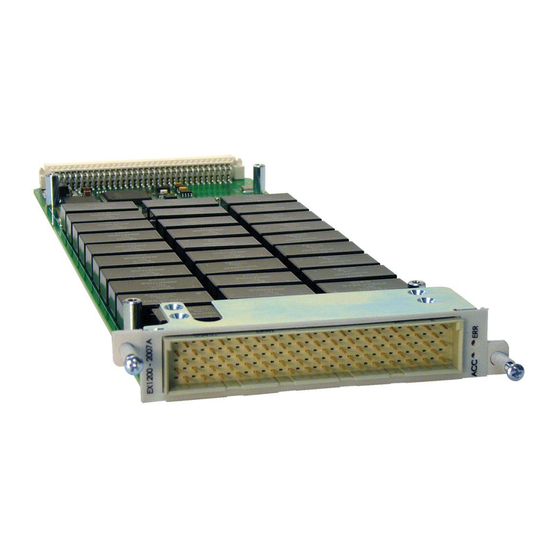
VTI Instruments EX1200 Series Manuals
Manuals and User Guides for VTI Instruments EX1200 Series. We have
3
VTI Instruments EX1200 Series manuals available for free PDF download: User Manual
VTI Instruments EX1200 Series User Manual (172 pages)
SWITCH CARDS
Brand:
VTI Instruments
| Category:
Network Hardware
| Size: 13 MB
Table of Contents
Table of Contents
2
Certification
6
Warranty
6
Limitation of Warranty
6
Restricted Rights Legend
6
Declaration of Conformity
6
General Safety Instructions
7
Terms and Symbols
7
Warnings
7
Support Resources
9
Section 1
10
Ntroduction
10
Overview
10
Plug-In Module Installation
10
Microwave Module Installation
11
Module Shielding/Grounding
11
Scanning
11
Application Environments
12
Section 2
13
Switching Overview
13
General Purpose Switching
13
Power Switching
13
Matrix/Multiplexer Switching
13
RF Switching
14
Section 3
15
Ex1200 Series Terminal Blocks
15
Introduction
15
Jumper Configuration
16
Terminal Block Receiver
17
Programming Overview
17
Measure Thermistor Temperature
17
Use Thermistor as a Reference Junction
18
Section 4
19
EX1200-2001 Plug-In Module
19
20-Channel 16 Amp SPST Switch
19
Connector Pins and Signals
19
Logical Diagram
21
EX1200-2001 Specifications
22
Relay Breaking Capacity
22
EX1200-2002 Plug-In Module
23
12-Channel 16 Amp Form C (SPDT) Switch
23
Connector Pins and Signals
23
Logical Diagram
24
EX1200-2002 Specifications
25
EX1200-2007A Plug-In Module
26
48-Channel 1000 V Multiplexer
26
Connector Pins and Signals
26
Logical Diagram
28
EX1200-2007A Specifications
29
EX1200-2008 Hplug-In Module
30
30-Channel 3 (1 X 10) High-Voltage Multiplexer
30
Connector Pins and Signals
30
Logical Diagram
32
EX1200-2008H Specifications
33
Ex1200-3001 Plug - in Module
34
X 64 2-Wire Multiplexer
34
Connector Pins and Signals
34
Logical Diagram
36
EX1200-3001 Specifications
38
Ex1200-3001Ds Plug - in Module
39
X 64 2-Wire Multiplexer with Discharge Circuit
39
Connector Pins and Signals
39
Logical Diagram
41
EX1200-3001DS Specifications
42
Ex1200-3048 Plug - in Module
43
48-Channel 300 V/ 2 a Multiplexer
43
Connector Pins and Signals
43
Logical Diagram
45
EX1200-3048 Specifications
47
EX1200-3048S Plug-In Module
48
48-Channel Two-Wire FET Multiplexer
48
Connector Pins and Signals
48
Logical Diagram
50
EX1200-3048S Specifications
52
Ex1200-3072 Plug - in Module
53
72-Channel 300 V/ 2 a Multiplexer
53
Connector Pins and Signals
53
Logical Diagram
55
EX1200-3072 Specifications
57
Ex1200-3096 Plug - in Module
58
96-Channel 100 V / 0.5 a Two-Wire Multiplexer
58
Connector Pins and Signals
58
Logical Diagram
61
EX1200-3096 Specifications
63
Ex1200-3164 Plug - in Module
64
1X4) 2-Wire 300 V/ 2 Amp Multiplexer
64
Connector Pins and Signals
64
Logical Diagram
66
EX1200-3164 Specifications
68
Ex1200-3824 Plug - in Module
69
(1 X 24) Solid State, 100V/100Ma Multiplexer
69
EX1200-3824 Standard Board
69
EX1200-3824 with Attenuator Option
69
Connector Pins and Signals
70
Logical Diagram
72
Ex1200-38Tb
73
EX1200-3824 Specifications
76
Ex1200-4003 Plug - in Module
77
Dual 4 X 16 Two-Wire Matrix, 300 V / 2 a
77
Logical Diagram
79
EX1200-4003 Specifications
81
EX1200-4128Plug-In Module
82
X 128 One-Wire Matrix, 150 V/0.5 a
82
Connector Pins and Signals
82
Logical Diagram
86
EX1200-4128 Specifications
88
EX1200-4260 Plug-In Module
89
X 60 2-Wire Matrix
89
Connector Pins and Signals
89
Logical Diagram
93
EX1200-4260 Specifications
94
Relay Breaking Capacity
94
EX1200-4264 Plug-In Module
95
X 64 2-Wire Matrix
95
Connector Pins and Signals
95
Logical Diagram
99
EX1200-4264 Specifications
100
Relay Breaking Capacity
100
Ex1200-5001 Plug - in Module
101
80-Channel 2 Amp Form a (SPST) Switch
101
Connector Pins and Signals
101
Logical Diagram
103
EX1200-5001 Specifications
105
EX1200-5002Plug-In Module
106
32-Channel, 2 Amp Form C (SPDT) Switch
106
Connector Pins and Signals
106
Logical Diagram
108
EX1200-5002 Specifications
110
Ex1200-5004 Plug - in Module
111
32-Channel, 5 a SPDT Switch
111
Connector Pins and Signals
111
Logical Diagram
113
EX1200-5004 Specifications
114
378Hex1200-5006 Plug - in Module
115
40-Channel 2 Amp Form a (SPST) Switch
115
Connector Pins and Signals
115
Logical Diagram
117
EX1200-5006 Specifications
119
EX1200-6101 Plug-In Module
120
SP4T RF Multiplexers, 1.3 Ghz
120
Connector Pins and Signals
120
Logical Diagram
122
EX1200-6101 Specifications
123
EX1200-6102 Plug-In Module
124
17-Channel (1X2) Coaxial Switches, 1.3Ghz
124
Connector Pins and Signals
124
Logical Diagram
126
EX1200-6102 Specifications
127
EX1200-6111 Plug-In Module
128
5-Channel SP4T Coaxial Switch
128
Connector Pins and Signals
128
Logical Diagram
130
EX1200-6111 Specifications
131
EX1200-6216 Plug-In Module
132
Dual 1 X 16 RF Mux, 1 Ghz Switch
132
Connector Pins and Signals
132
Logical Diagram
134
EX1200-6216 Specifications
135
EX1200-6216HV Plug-In Module
136
Dual (1X16) 500 V 250 Mhz Multiplexers
136
Connector Pins and Signals
136
Logical Diagram
138
EX1200-6216HV Specifications
139
Ex1200-6301 Plug - in Module
140
Channel SP4T, RF Multiplexer, 50 Ω, 3 Ghz
140
Connector Pins and Signals
140
Logical Diagram
141
EX1200-6301 Specifications
142
EX1200-6301T Plug-In Module
143
Channel SP4T, Self-Terminated RF Multiplexer, 50 Ω, 3 Ghz
143
Connector Pins and Signals
143
Logical Diagram
144
EX1200-6301T Specifications
145
EX1200-7100 Plug-In Module
146
Ghz Microwave Switch Carrier and Relay Driver
146
Front Panel Enclosure
146
Microwave Switch Modules
147
7102 Microwave Module
147
7104 Microwave Module
148
7122 Microwave Module
149
Installing a Switch Module
149
EX1200-7100 Carrier Front Panel Connectors
150
EX1200-7100 Soft Front Panel
150
EX1200-7100 Specifications
151
Ex1200-Smp
152
EX1200-SMP4 Carrier Module
152
EX1200-08442 I/O Matrix Card
153
Smp Architecture
154
Connector Pins and Signals
154
Logical Diagram
155
EX1200-08442 Specifications
159
Inserting IO Matrix Cards into SMP-4 Module
160
Inserting SMP-4 Module into EX1268A Chassis
161
Removing SMP-4 Module from the EX1268A Chassis
161
Removing IO Matrix Cards from SMP-4 Module and EX1268A Chassis
162
Smp Firmware Update Procedure
163
Ppendixa
167
Power Consumption and Weight
167
Reference Tables
167
Ppendixb
169
Switch Card Accessories
169
List of Accessories
169
26-Pin Connector
169
41-Pin Connector
170
160-Pin Connector
171
Advertisement
VTI Instruments EX1200 Series User Manual (161 pages)
HIGH-DENSITY SWITCH/MEASURE AND CONTROL SYSTEMS
Brand:
VTI Instruments
| Category:
Switch
| Size: 31 MB
Table of Contents
Table of Contents
3
Certification
6
Warranty
6
Limitation of Warranty
6
Trademarks
6
Restricted Rights Legend
6
Declaration of Conformity
7
Product Name
7
General Safety Instructions
8
Terms and Symbols
8
Warnings
8
Support Resources
10
Section 1
12
Introduction
12
Features
12
EX1200 System Specifications
15
EX1200 Series 1 U, Full Rack Mainframe Dimensional Diagram
17
EX1200 Series 1 U, Half Rack Mainframe Dimensional Diagram
18
EX1200 Series 3 U Mainframe Dimensional Diagram
19
EX1200 Series 3 U Mainframe Front Panels
20
EX1200 Series DMM Specifications
21
Reading Rate
28
Explanation of Specifications
29
Maximizing Measurement Performance
31
Section 2
34
Preparation for Use
34
Unpacking
34
Determine System Power Requirements
34
Installation Location
34
Warm-Up Time
35
Plug-In Module Installation
35
Removing Plug-In Modules
36
EX1202/EX1262 Mainframe Installation Options
36
EX1206/EX1266 Mainframe Installation Options
45
Installation Diagram
46
Mainframe Installation Options
50
Blanking Panel
54
Connecting/Disconnecting Line Power
54
Software Installation
54
Driver Installation
55
Network Configuration
56
Network Troubleshooting
57
Time Configuration
62
Section 3
64
Basic Mainframe Operation
64
Input Connections
64
DMM Bus
68
LED Indicators
69
Locking
69
Triggering
69
Section 4
70
Basic Ex1200 DMM Operation
70
Overview
70
DMM Input Connections
71
DMM Measurement Basics
73
Select an Input Connector
73
Configure the Measurement
74
Configure Triggering
74
Take the Measurement
77
Retrieve the Data
77
DMM Functions
78
Range
78
Resolution
79
Integration/Aperture Time
80
Auto-Zero
80
Limits
81
Math Functions
81
DC Voltage Measurements
82
AC Voltage Measurements
85
DC and AC Current Measurements
88
Resistance Measurements
89
Frequency/Period Measurements
91
Frequency Measurements
93
Temperature Measurements
94
DMM Front Panel
98
Self-Test
101
Section 5
102
Scanner Overview
102
Overview
102
Section 6
104
Triggering
104
Overview
104
Section 7
104
Page Operation
106
Introduction
106
General Web
107
Soft Front Panel Main Page
108
Scanner Soft Front Panel
109
Instrument Soft Front Panels
116
Switch Soft Front Panels
116
DMM Soft Front Panel
119
DMM Calibration Web Page
124
Network Configuration
127
Time Configuration
128
LXI Synchronization
130
LXI Identification
132
Blink LAN Indicator
133
Change Password
133
Upgrade
134
Section 8
140
Programming
140
Programming References
140
Section 9
142
Maintenance
142
Replaceable Fuse
142
DMM Removal/Replacement
142
Ex1200 DMM Calibration /Verification
145
Introduction
145
Required Resources
145
Setting up the Instruments
145
Connecting to the EX1200
146
Login into SFP
147
Time Configuration
148
Performing Calibration
148
Function Selection
149
Performing Verification
150
Ppendixa
152
Onboard Memory
152
Memory Listings and Clearing Procedures
152
Appendixb
154
Power Consumption
154
Plug-In Module Power Consumption
154
Application Note
155
Overview
155
Ex12X2 and Ex12X6 Power Consumption Calculation
155
Ex12X8 Power Consumption Calculation
156
Index
158
VTI Instruments EX1200 Series User Manual (159 pages)
HIGH-DENSITY SWITCH/MEASURE AND CONTROL SYSTEMS
Brand:
VTI Instruments
| Category:
Control Systems
| Size: 10 MB
Table of Contents
Table of Contents
2
Certification
5
Warranty
5
Limitation of Warranty
5
Trademarks
5
Restricted Rights Legend
5
Declaration of Conformity
6
General Safety Instructions
7
Terms and Symbols
7
Warnings
7
Support Resources
9
Section 1
11
Introduction
11
Features
11
EX1200 System Specifications
14
EX1200 Series 1 U, Full Rack Mainframe Dimensional Diagram
16
EX1200 Series 1 U, Half Rack Mainframe Dimensional Diagram
17
EX1200 Series 3 U Mainframe Dimensional Diagram
18
EX1200 Series 3 U Mainframe Front Panels
19
EX1200 Series DMM Specifications
20
Explanation of Specifications
28
Maximizing Measurement Performance
30
Section 2
33
Preparation for Use
33
Unpacking
33
Determine System Power Requirements
33
Installation Location
33
Warm-Up Time
34
Plug-In Module Installation
34
Removing Plug-In Modules
35
EX1202/EX1262 Mainframe Installation Options
35
EX1206/EX1266 Mainframe Installation Options
44
Mainframe Installation Options
49
Blanking Panel
53
Connecting/Disconnecting Line Power
53
Software Installation
53
Driver Installation
54
Network Configuration
55
Network Troubleshooting
55
Time Configuration
61
Section 3
63
Basic Mainframe Operation
63
Input Connections
63
DMM Bus
67
LED Indicators
68
Locking
68
Triggering
68
Section 4
69
Basic Ex1200 DMM Operation
69
Overview
69
DMM Input Connections
70
DMM Measurement Basics
72
Select an Input Connector
72
Configure the Measurement
73
Configure Triggering
73
Take the Measurement
76
Retrieve the Data
76
DMM Functions
77
Range
77
Resolution
78
Integration/Aperture Time
79
Auto-Zero
79
Limits
80
Math Functions
80
DC Voltage Measurements
81
AC Voltage Measurements
84
DC and AC Current Measurements
87
Resistance Measurements
88
Frequency/Period Measurements
90
Temperature Measurements
92
Self-Test
99
Section 5
101
Scanner Overview
101
Overview
101
Section 6
103
Triggering
103
Overview
103
Section 7
105
Web
105
Eb Age Peration
105
Introduction
105
General Web
106
Soft Front Panel Main Page
107
Scanner Soft Front Panel
108
Instrument Soft Front Panels
115
Switch Soft Front Panels
115
DMM Soft Front Panel
118
DMM Calibration Web Page
123
Network Configuration
126
Time Configuration
127
LXI Synchronization
129
LXI Identification
131
Blink LAN Indicator
132
Change Password
132
Upgrade
133
Section 8
139
Programming
139
Programming References
139
Section 9
139
Maintenance
141
Replaceable Fuse
141
DMM Removal/Replacement
141
Ex1200 DMM Calibration /Verification
144
Introduction
144
Required Resources
144
Setting up the Instruments
144
Connecting to the EX1200
145
Login into SFP
146
Time Configuration
147
Performing Calibration
147
Performing Verification
149
Appendixa
151
Onboard Memory
151
Memory Listings and Clearing Procedures
151
Appendixb
153
Power Consumption
153
Plug-In Module Power Consumption
153
Application Note
154
Overview
154
Ex12X2 and Ex12X6 Power Consumption Calculation
154
Ex12X8 Power Consumption Calculation
155
Index
157
Advertisement
Advertisement
Related Products
VTI Instruments EX1200-2001
VTI Instruments EX1200-2002
VTI Instruments EX1200-2007A
VTI Instruments EX1200-2008H
VTI Instruments EX1200-3001
VTI Instruments EX1200-3001DS
VTI Instruments EX1200-3048
VTI Instruments EX1200-3048S
VTI Instruments EX1200-3072
VTI Instruments EX1200-3096
VTI Instruments Categories
Measuring Instruments
Network Card
Switch
Network Hardware
Media Converter
More VTI Instruments Manuals
Login
Sign In
OR
Sign in with Facebook
Sign in with Google
Upload manual
Upload from disk
Upload from URL