
Related Manuals for VTI Instruments EX1200 Series

Summary of Contents for VTI Instruments EX1200 Series
- Page 1 EX1200 S ERIES WITCH ARDS ’ ANUAL P/N: 82-0127-001 May 26 2016 VTI Instruments Corp. 2031 Main Street Irvine, CA 92614-6509 (949) 955-1894...
-
Page 2: Table Of Contents
VTI Instruments Corp. ABLE OF ONTENTS NTRODUCTION Certification ................................6 Warranty ................................6 Limitation of Warranty ............................6 Restricted Rights Legend ............................6 Declaration of Conformity ............................ 6 ..........................7 ENERAL AFETY NSTRUCTIONS Terms and Symbols .............................. 7 Warnings ................................7 ............................... - Page 3 www.vtiinstruments.com 30-Channel 3 (1 x 10) High-Voltage Multiplexer ....................30 Connector Pins and Signals ..........................30 Logical Diagram ..............................32 EX1200-2008H Specifications ........................... 33 EX1200-3001 P ........................... 34 ODULE 1 x 64 2-wire Multiplexer ........................... 34 Connector Pins and Signals ..........................34 Logical Diagram ..............................
- Page 4 VTI Instruments Corp. 2 x 60 2-Wire Matrix ............................89 Connector Pins and Signals ..........................89 Logical Diagram ..............................93 EX1200-4260 Specifications ..........................94 Relay Breaking Capacity ............................ 94 EX1200-4264 P ........................... 95 ODULE 2 x 64 2-Wire Matrix ............................95 Connector Pins and Signals ..........................
- Page 5 www.vtiinstruments.com 4 Channel SP4T, RF Multiplexer, 50 Ω, 3 GHz ..................... 140 Connector Pins and Signals ..........................140 Logical Diagram ............................... 141 EX1200-6301 Specifications ..........................142 EX1200-6301T P ........................143 ODULE 4 Channel SP4T, Self-terminated RF Multiplexer, 50 Ω, 3 GHz ..............143 Connector Pins and Signals ..........................
-
Page 6: Certification
VTI Instruments Corp. shall not be liable for injury to property other than the goods themselves. Other than the limited warranty stated above, VTI Instruments Corp. makes no other warranties, express, or implied, with respect to the quality of product beyond the description of the goods on the face of the contract. -
Page 7: General Safety Instructions
Use Proper Power Source use a power source that applies other than the specified voltage. Prior to using the EX1200 series switch cards, it is imperative that Power Consumption the power consumption of all cards that will be installed in the mainframe be calculated on all power supply rails. - Page 8 VTI Instruments Corp. ARNINGS To avoid electric shock or fire hazard, do not operate this product Avoid Electric Shock with the covers removed. Do not connect or disconnect any cable, probes, test leads, etc. while they are connected to a voltage source.
-
Page 9: Support Resources
UPPORT ESOURCES Support resources for this product are available on the Internet and at VTI Instruments customer support centers. VTI Instruments Corp. World Headquarters VTI Instruments Corp. 2031 Main Street Irvine, CA 92614-6509 Phone: (949) 955-1894 Fax: (949) 955-3041... -
Page 10: Section 1
ODULE NSTALLATION All EX1200 series switch cards must be installed into an EX1200 series mainframe to be used. The mainframe operates on 90 V to 250 V at 50 Hz/60 Hz which is used to supply the cards the dc voltages required for the cards to function properly. -
Page 11: Microwave Module Installation
www.vtiinstruments.com The maximum safe voltage for an EX1200 system is determined by the plug-in card with the lowest voltage rating. ICROWAVE ODULE NSTALLATION For the EX1200-7100 Plug-in Module, microwave switch modules can be installed. Before installing a switch module into the EX1200-7100 carrier, ensure that the mainframe is powered down. -
Page 12: Application Environments
VTI Instruments Corp. PPLICATION NVIRONMENTS The EX1200 switching platform supports a wide variety of application environments. The switches can be manually controlled through the embedded, web-based soft front panel or programmatically on a Windows-based PC through the provided IVI VTEXSwitch driver controlled on most platforms through the C++ driver. -
Page 13: Section 2
www.vtiinstruments.com ECTION 322H WITCHING VERVIEW ENERAL URPOSE WITCHING When selecting switch cards for a test system, the following should be taken into consideration: Power Specifications Minimum Contact Rating Switching Time Bandwidth The relay must be able to accommodate both the voltage, current, and total power that will be switched and all of these specifications should be checked before making a selection. -
Page 14: Rf Switching
VTI Instruments Corp. 2-1: S IGURE REAKING ELAYS When programming switches to perform 2-wire and 4-wire measurements, the 2-wire and 4-wire channel names must be used. For “standard” matrix cards (i.e. 2-banks of paired H/L inputs), the 2- and 4-wire name, the 1-wire names is used as the base. The convention is illustrated in... -
Page 15: Section 3
LOCKS NTRODUCTION VTI offers differential and single-ended terminal blocks (TBs) for many of the EX1200 series switch cards. The terminal blocks can be used to simplify cabling. In addition to this, the differential terminal blocks also provide users an on-board thermistor for cold junction compensation (CJC) when making temperature measurements. -
Page 16: Jumper Configuration
T1 and T2 of the terminal block are connected. Figure 3-2, an EX1200-TB160-1 is shown where T1 and T2 are connected to CH1_1L and 327H CH1_1H, respectively. The channels are indicated in the Terminal Block Pin Mapping discussion for each switch card. EX1200 Series Terminal Blocks... -
Page 17: Terminal Block Receiver
Either the VTEXScanner driver or the scanner soft front panel can be used to perform this sequence. 1) Set the DMM to measure temperature using the thermistor. Set the DMM function to Temperature. Set the transducer type to Thermistor. Set the thermistor resistance to 10000 (the thermistor is 10 kΩ). EX1200 Series Terminal Blocks... -
Page 18: Use Thermistor As A Reference Junction
(e.g. CH1_1=RefJunction). Add another scan step with a sweep phase that scans another channel (e.g. CH1_2=TEMP). The setup phase can be ignored for this example. 6) Initiate & Read Initiate the scan Read back the data EX1200 Series Terminal Blocks... -
Page 19: Section 4
Since these modules typically switch power to the UUT or interface, the digital input lines on the EX1200 series mainframes support the ability to force all relays automatically to their normally open state if a fault condition occurs. This approach instantly removes all power to the UUT or interface. - Page 20 VTI Instruments Corp. Signal Signal CH_1NO CH_11COM CH_1COM CH_12NO CH_2NO CH_12COM CH_2COM CH_13NO CH_3NO CH_13COM CH_3COM CH_14NO CH_4NO CH_14COM CH_4COM CH_15NO CH_5NO CH_15COM CH_5COM CH_16NO CH_6NO CH_16COM CH_6COM CH_17NO CH_7NO CH_17COM CH_7COM CH_18NO CH_8NO CH_18COM CH_8COM CH_19NO CH_9NO CH_19COM CH_9COM...
-
Page 21: Logical Diagram
www.vtiinstruments.com OGICAL IAGRAM 4-2: EX1200-2001 L IGURE OGICAL IAGRAM EX1200-2001 Plug-in Module... -
Page 22: Ex1200-2001 Specifications
VTI Instruments Corp. EX1200-2001 S PECIFICATIONS ENERAL PECIFICATIONS HANNEL OUNT 20 SPST ELAY Electromechanical, fail-safe AXIMUM WITCHING OLTAGE 250 V ac rms, 125 V dc AXIMUM WITCHING URRENT 16 A AXIMUM WITCHING OWER 480 W dc, 2000 VA per channel (see the... -
Page 23: Ex1200-2002 Plug-In Module
Since these modules typically switch power to the UUT or interface, the digital input lines on the EX1200 series mainframes support the ability to force all relays automatically to their normally open state if a fault condition occurs. This approach instantly removes all power to the UUT or interface. -
Page 24: Logical Diagram
VTI Instruments Corp. Signal Signal CH_1NO CH_8NO CH_1COM CH_8COM CH_1NC CH_8NC CH_2NO CH_9NO CH_2COM CH_9COM CH_2NC CH_9NC CH_3NO CH_10NO CH_3COM CH_10COM CH_3NC CH_10NC CH_4NO CH_11NO CH_4COM CH_11COM CH_4NC CH_11NC CH_5NO CH_12NO CH_5COM CH_12COM CH_5NC CH_12NC CH_6NO UNUSED CH_6COM UNUSED CH_6NC... -
Page 25: Ex1200-2002 Specifications
www.vtiinstruments.com EX1200-2002 S PECIFICATIONS ENERAL PECIFICATIONS HANNEL OUNT 12 SPDT ELAY Electromechanical, fail-safe AXIMUM WITCHING OLTAGE 250 V ac rms, 125 V dc AXIMUM WITCHING URRENT 16 A AXIMUM WITCHING OWER 480 W dc, 2000 VA per channel INIMUM ONTACT ATING 12 V dc, 0.1 A *This value is in reference to a resistive load. -
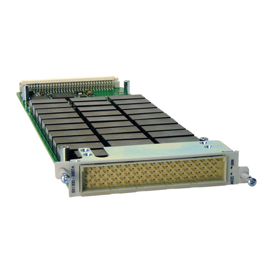
Page 26: Ex1200-2007A Plug-In Module
Up to 144 2-wire channels can be accommodated in a single EX1200 series mainframe for maximum density, or combined with other EX1200 series modules to create a flexible system switch. - Page 27 www.vtiinstruments.com Row A Row B Row C Row D Row E SHIELD CH2_1L CH2_1H UNUSED CH1_1W SHIELD CH2_2L CH2_2H CH1_COMH CH1_COML SHIELD CH2_3L CH2_3H CH1_1H CH1_1L SHIELD CH2_4L CH2_4H CH1_2H CH1_2L SHIELD CH2_5H CH2_5L CH1_3H CH1_3L SHIELD CH2_6H CH2_6L CH1_4H CH1_4L SHIELD CH2_7H...
-
Page 28: Logical Diagram
VTI Instruments Corp. OGICAL IAGRAM CH1_COML (Pin E3) CH2_COML (Pin E29) CH1_COMH (Pin D4) CH2_COMH (Pin D30) CH1_1W (Pin E1) CH2_1W (Pin E31) CH1_1H (Pin D6) CH2_1H (Pin C1) CH1_1L (Pin E5) CH2_1L (Pin B2) CH1_2H (Pin D8) CH2_2H (Pin C3) -
Page 29: Ex1200-2007A Specifications
www.vtiinstruments.com EX1200-2007A S PECIFICATIONS ENERAL PECIFICATIONS HANNEL OUNT (1 x 24) 2-wire, dual (1 x 12) 2-wire, or dual (1 x 24) 1-wire ELAY Reed AXIMUM WITCHING OLTAGE 1000 V dc / 700 V ac rms AXIMUM WITCHING URRENT AXIMUM ARRY URRENT AXIMUM... -
Page 30: Ex1200-2008 Hplug-In Module
All relays are independently controllable. It is the highest density module in its class capable of switching signals to 1000 V. The EX1200-2008 can be mixed and matched with other EX1200 series plug-in modules in a single mainframe to construct a flexible mixed-signal switching subsystem. - Page 31 www.vtiinstruments.com Row A Row B Row C Row D Row E Signal Signal Signal Signal Signal SHIELD CH1_1 CH1_2 UNUSED CH1_COM SHIELD CH1_3 CH1_4 UNUSED SHIELD SHIELD CH1_5 CH1_6 UNUSED SHIELD SHIELD CH1_7 CH1_8 UNUSED SHIELD SHIELD CH1_9 CH1_10 UNUSED SHIELD SHIELD CH2_1...
-
Page 32: Logical Diagram
VTI Instruments Corp. OGICAL IAGRAM 4-9: EX1200-2008H L IGURE OGICAL IAGRAM EX1200-2008 HPlug-in Module... -
Page 33: Ex1200-2008H Specifications
www.vtiinstruments.com EX1200-2008H S PECIFICATIONS ENERAL PECIFICATIONS HANNEL OUNT Three (1 x 10) single-wire channels ELAY High-voltage reed relays AXIMUM WITCHING OLTAGE 1000 V dc AXIMUM WITCHING URRENT AXIMUM ARRY URRENT AXIMUM WITCHING OWER 25 W dc (resistive load) INIMUM ONTACT ATING 5 V dc, 0.1 A *This value is in reference to a resistive load. -
Page 34: Ex1200-3001 Plug - In Module
VTI Instruments Corp. EX1200-3001 P ODULE 64 2- WIRE ULTIPLEXER The EX1200-3001 high-density multiplexer module is designed for scanning of multiple points to a common bus, in either 1-, 2-, or 4-wire configurations, either synchronously with the EX1200 system DMM scan function, or asynchronously as a system switch to other devices through LXI LAN messages or the hardware trigger bus. - Page 35 www.vtiinstruments.com Row A Row B Row C Row D Row E Signal Signal Signal Signal Signal CH1_1W CH1_COMH CH1_1H CH1_2H CH1_3H SHIELD CH1_COML CH1_1L CH1_2L CH1_3L CH1_4H CH1_5H CH1_6H CH1_7H CH1_8H CH1_4L CH1_5L CH1_6L CH1_7L CH1_8L CH2_1W CH2_COMH CH2_1H CH2_2H CH2_3H SHIELD CH2_COML...
-
Page 36: Logical Diagram
VTI Instruments Corp. OGICAL IAGRAM 4-11: EX1200-3001 L IGURE OGICAL IAGRAM EX1200-3001 Plug-in Module... - Page 37 www.vtiinstruments.com Conn Conn Conn Conn Signal Signal Signal Signal CH1_7L CH7_7L CH7_5L T121 CH6_1W CH1_7H CH7_7H CH7_5H SHIELD T122 CH2_2L CH7_2L CH8_1L T123 CH5_4H CH2_2H CH7_2H CH8_1H CH5_4L T124 CH2_7L CH6_7L CH8_6L CH5_1W T125 CH2_7H CH6_7H CH8_6H SHIELD T126 CH3_2L CH6_2L CH1_1L CH4_4H...
-
Page 38: Ex1200-3001 Specifications
VTI Instruments Corp. EX1200-3001 S PECIFICATIONS ENERAL PECIFICATIONS HANNEL OUNT Eight individual (1 x 8) 2-wire or eight (1 x 16) 1-wire ELAY Electromechanical, fail-safe AXIMUM WITCHING OLTAGE 300 V ac rms, 300 V dc AXIMUM WITCHING URRENT AXIMUM WITCHING... -
Page 39: Ex1200-3001Ds Plug - In Module
www.vtiinstruments.com EX1200-3001DS P ODULE 64 2- WIRE ULTIPLEXER WITH ISCHARGE IRCUIT The EX1200-3001DS high-density multiplexer module is designed for scanning of multiple points to a common bus, in either 1-, 2-, or 4-wire configurations, either synchronously with the EX1200 system DMM scan function, or asynchronously as a system switch to other devices through LXI LAN messages or the hardware trigger bus. - Page 40 VTI Instruments Corp. Row A Row B Row C Row D Row E Signal Signal Signal Signal Signal CH1_1W CH1_COMH CH1_1H CH1_2H CH1_3H SHIELD CH1_COML CH1_1L CH1_2L CH1_3L CH1_4H CH1_5H CH1_6H CH1_7H CH1_8H CH1_4L CH1_5L CH1_6L CH1_7L CH1_8L CH2_1W CH2_COMH...
-
Page 41: Logical Diagram
www.vtiinstruments.com OGICAL IAGRAM 4-13: EX1200-3001DS L IGURE OGICAL IAGRAM EX1200-3001DS Plug-in Module... -
Page 42: Ex1200-3001Ds Specifications
VTI Instruments Corp. EX1200-3001DS S PECIFICATIONS ENERAL PECIFICATIONS HANNEL OUNT Eight individual (1 x 8) 2-wire or eight (1 x 16) 1-wire ELAY Electromechanical, fail-safe AXIMUM WITCHING OLTAGE 300 V ac rms, 300V dc AXIMUM WITCHING URRENT AXIMUM WITCHING OWER 60 W dc, 125 VA *Maximum switched power is at 30 V/ 2 A dc. -
Page 43: Ex1200-3048 Plug - In Module
www.vtiinstruments.com EX1200-3048 P ODULE 48-C 300 V/ 2 A M HANNEL ULTIPLEXER EX1200-3048 high-density multiplexer modules are designed for scanning multiple points to a common bus in either 2- or 4-wire configurations, either synchronously, with the EX1200 system DMM scan function, or asynchronously, as a system switch to other devices through LXI LAN messages or the hardware trigger bus. - Page 44 VTI Instruments Corp. Signal Signal Signal Signal Signal CH1_1L CH1_5L CH1_10L CH1_15L CH1_20L CH1_1H CH1_5H CH1_10H CH1_15H CH1_20H CH1_2L CH1_6L CH1_11L CH1_16L CH1_21L CH1_2H CH1_6H CH1_11H CH1_16H CH1_21H CH1_COML CH1_7L CH1_12L CH1_17L CH1_22L CH1_COMH CH1_7H CH1_12H CH1_17H CH1_22H CH1_3L CH1_8L...
-
Page 45: Logical Diagram
www.vtiinstruments.com OGICAL IAGRAM 4-15: EX1200-3048 L IGURE OGICAL IAGRAM EX1200-3048 Plug-in Module... - Page 46 VTI Instruments Corp. Conn Conn Conn Conn Signal Signal Signal Signal CH1_1L CH1_9L CH2_13L CH2_19L CH1_1H CH1_9H CH2_13H CH2_19H CH1_2L CH2_5L CH2_14L UNUSED CH1_2H CH2_5H CH2_14H CH3_2L CH1_COML CH2_6L UNUSED CH1_20L CH1_COMH CH2_6H CH3_2I CH1_20H CH1_3L CH2_7L CH1_15L CH1_21L CH1_3H...
-
Page 47: Ex1200-3048 Specifications
www.vtiinstruments.com EX1200-3048 S PECIFICATIONS ENERAL PECIFICATIONS HANNEL OUNT 48 two-wire or 24 four-wire ELAY Electromechanical, fail-safe AXIMUM WITCHING OLTAGE 300 V dc, 300 V ac rms AXIMUM WITCHING URRENT AXIMUM WITCHING OWER 60 W dc, 125 VA *Maximum switched power is at 30 V/ 2 A dc. Max switched power is derated non-linearly as voltage is increased. INIMUM ONTACT ATING... -
Page 48: Ex1200-3048S Plug-In Module
VTI Instruments Corp. EX1200-3048S P ODULE 48-C FET M HANNEL ULTIPLEXER The EX1200-3048S is a high-density FET multiplexer module designed for scanning of multiple points to a common bus, in either 2- or 4-wire configurations, either synchronously with the EX1200 system DMM scan function, or asynchronously as a system switch to other devices through LXI LAN messages or the hardware trigger bus. - Page 49 www.vtiinstruments.com Signal Signal Signal Signal Signal CH1_1L CH1_5L CH1_10L CH1_15L CH1_20L CH1_1H CH1_5H CH1_10H CH1_15H CH1_20H CH1_2L CH1_6L CH1_11L CH1_16L CH1_21L CH1_2H CH1_6H CH1_11H CH1_16H CH1_21H CH1_COML CH1_7L CH1_12L CH1_17L CH1_22L CH1_COMH CH1_7H CH1_12H CH1_17H CH1_22H CH1_3L CH1_8L CH1_13L CH1_18L CH1_23L CH1_3H CH1_8H...
-
Page 50: Logical Diagram
VTI Instruments Corp. OGICAL IAGRAM CH1_24L (Pin 93) CH1_16L (Pin 66) CH1_8L (Pin 28) CH1_24H (Pin 94) CH1_16H (Pin 67) CH1_8H (Pin 29) CH1_23L (Pin 91) CH1_15L (Pin 64) CH1_7L (Pin 26) CH1_23H (Pin 92) CH1_15H (Pin 65) CH1_7H (Pin 27) - Page 51 www.vtiinstruments.com Conn Conn Conn Conn Signal Signal Signal Signal CH1_1L CH1_9L CH2_13L CH2_19L CH1_1H CH1_9H CH2_13H CH2_19H CH1_2L CH2_5L CH2_14L UNUSED CH1_2H CH2_5H CH2_14H SHIELD CH1_COML CH2_6L UNUSED CH1_20L CH1_COMH CH2_6H SHIELD CH1_20H CH1_3L CH2_7L CH1_15L CH1_21L CH1_3H CH2_7H CH1_15H CH1_21H CH1_4L CH2_8L...
-
Page 52: Ex1200-3048S Specifications
VTI Instruments Corp. EX1200-3048S S PECIFICATIONS ENERAL PECIFICATIONS HANNEL OUNT 48 two-wire or 24 four-wire ELAY Opto-isolated solid-state AXIMUM WITCHING OLTAGE 250 V AXIMUM WITCHING URRENT 0.2 A AXIMUM WITCHING OWER 6 W/4.2 VA ATED WITCH PERATIONS Unlimited (solid state relays) WITCHING <... -
Page 53: Ex1200-3072 Plug - In Module
www.vtiinstruments.com EX1200-3072 P ODULE 72-C 300 V/ 2 A M HANNEL ULTIPLEXER The EX1200-3072 high-density multiplexer modules are designed for scanning of multiple points to a common bus, in either 2- or 4-wire configurations, either synchronously with the EX1200 system DMM scan function, or asynchronously as a system switch to other devices through LXI LAN messages or the hardware trigger bus. - Page 54 VTI Instruments Corp. Row A Row B Row C Row D Row E Signal Signal Signal Signal Signal UNUSED SHIELD SHIELD SHIELD SHIELD CH1_3L CH1_4L CH1_8L CH1_7L CH1_1L CH1_3H CH1_4H CH1_8H CH1_7H CH1_1H CH1_5L CH1_6L CH1_2L CH1_9L CH1_11L CH1_5H CH1_6H...
-
Page 55: Logical Diagram
www.vtiinstruments.com OGICAL IAGRAM CH1_36L (Pin A12) CH1_27L (Pin D8) CH1_18L (Pin E6) CH1_9L (Pin D4) CH1_18H (Pin E7) CH1_9H (Pin D5) CH1_36H (Pin A13) CH1_27H (Pin D9) CH1_35L (Pin D14) CH1_26L (Pin B8) CH1_17L (Pin D6) CH1_8L (Pin C2) CH1_35H (Pin D15) CH1_26H (Pin B9) CH1_17H (Pin D7) CH1_8H (Pin C3) - Page 56 VTI Instruments Corp. Conn Conn Conn Conn Signal Signal Signal Signal CH1_1L CH1_21L CH2_1L CH2_21L T121 CH1_1H CH1_21H CH2_1H CH2_21H T122 CH1_2L CH1_22L CH2_2L CH2_22L T123 CH1_2H CH1_22H CH2_2H CH2_22H T124 CH1_3L CH1_23L CH2_3L CH2_23L T125 CH1_3H CH1_23H CH2_3H CH2_23H...
-
Page 57: Ex1200-3072 Specifications
www.vtiinstruments.com EX1200-3072 S PECIFICATIONS ENERAL PECIFICATIONS HANNEL OUNT (1 x 72) 2-wire, dual (1 x 36) 2-wire, or (1 x 36) 4-wire ELAY Electromechanical, fail-safe AXIMUM WITCHING OLTAGE 300 V ac rms, 300 V dc AXIMUM WITCHING URRENT AXIMUM WITCHING OWER 60 W dc, 125 VA *Maximum switched power is at 30 V/ 2 A dc. -
Page 58: Ex1200-3096 Plug - In Module
VTI Instruments Corp. EX1200-3096 P ODULE 96-C 100 V / 0.5 A T HANNEL ULTIPLEXER The EX1200-3096 high-density multiplexer modules are designed for scanning of multiple points to a common bus, in either 2- or 4-wire configurations, either synchronously with the EX1200 system DMM scan function, or asynchronously as a system switch to other devices through LXI LAN messages or the hardware trigger bus. - Page 59 www.vtiinstruments.com Row A Row B Row C Row D Signal Signal Signal Signal CH1_1L CH2_COML CH1_25L SHIELD CH1_1H CH2_24H CH1_25H CH2_48H CH1_2L CH2_24L CH1_26L CH2_48L CH1_2H CH2_23H CH1_26H CH2_47H CH1_3L CH2_23L CH1_27L CH2_47L CH1_3H CH2_22H CH1_27H CH2_46H CH1_4L CH2_22L CH1_28L CH2_46L CH1_4H CH2_21H...
- Page 60 VTI Instruments Corp. The module also incorporates ground pins, labeled “GND_C” above. These pins tie the module to 354H chassis ground. Note that the SHIELD pins are not tied to ground and have no electrical connections. EX1200-3096 Plug-in Module...
-
Page 61: Logical Diagram
www.vtiinstruments.com OGICAL IAGRAM 4-21: EX1200-3096 L IGURE OGICAL IAGRAM EX1200-3096 Plug-in Module... - Page 62 VTI Instruments Corp. Conn Conn Conn Conn Signal Signal Signal Signal CH1_1L CH1_8H T103 CH2_27L T154 CH2_41H CH1_1H CH1_19L T104 CH2_27H T155 CH2_29L CH1_13L CH1_19H T105 CH2_39L T156 CH2_29H CH1_13H CH1_7L T106 CH2_39H T157 CH2_40L CH1_2L CH1_7H T107 CH2_26L T158...
-
Page 63: Ex1200-3096 Specifications
www.vtiinstruments.com EX1200-3096 S PECIFICATIONS ENERAL PECIFICATIONS HANNEL OUNT (1 x 96) 2-wire, dual (1 x 48) 2-wire, or (1 x 48) 4-wire ELAY Electromechanical, fail-safe AXIMUM WITCHING OLTAGE 220 V ac rms, 240 V dc AXIMUM WITCHING URRENT AXIMUM WITCHING OWER 30 W dc (resistive), 37.5 VA (resistive) INIMUM... -
Page 64: Ex1200-3164 Plug - In Module
The analog bus can also be routed directly to the optional EX1200 series 6.5 digit DMM for direct measurements across the backplane further reduce external wiring. Stub-breaking relays remove the module from the analog bus to minimize a module’s effect on measurements being made through other modules. - Page 65 www.vtiinstruments.com Row A Row B Row C Row D Row E Signal Signal Signal Signal Signal CH5_COMH CH4_2H CH4_COMH CH5_2H CH5_4H CH5_COML CH4_2L CH4_COML CH5_2L CH5_4L CH5_3H CH4_4H CH6_4H CH4_1H CH5_1H CH5_3L CH4_4L CH6_4L CH4_1L CH5_1L CH4_3H CH3_2H CH3_COMH CH6_2H CH6_COMH CH4_3L CH3_2L...
-
Page 66: Logical Diagram
VTI Instruments Corp. OGICAL IAGRAM 4-23: EX1200-3164 L IGURE OGICAL IAGRAM EX1200-3164 Plug-in Module... - Page 67 www.vtiinstruments.com Conn Conn Conn Conn Signal Signal Signal Signal CH4_1L CH11_2L CH11_4L CH9_4H T121 CH4_1H CH11_2H CH11_4H CH9_4L T122 CH6_2L CH13_1L CH12_2L CH16_COMH T123 CH6_2H CH13_1H CH12_2H CH16_COML T124 CH3_1L CH10_1L CH13_COML CH1_3H T125 CH3_1H CH10_1H CH13_COMH CH1_3L T126 CH7_2L CH14_1L CH4_COML CH8_3H...
-
Page 68: Ex1200-3164 Specifications
VTI Instruments Corp. EX1200-3164 S PECIFICATIONS ENERAL PECIFICATIONS HANNEL OUNT Configured as either 16 (1x4), 8 (1x8), 4 (1x16), 2 (1x32) or 1 (1x64) 2-wire multiplexers ELAY Electromechanical, fail-safe AXIMUM WITCHING OLTAGE 300 V dc, 300 V ac rms AXIMUM... -
Page 69: Ex1200-3824 Plug - In Module
www.vtiinstruments.com EX1200-3824 P ODULE 8 (1 24) S , 100V/100 OLID TATE ULTIPLEXER The EX1200-3824 is a high speed multiplexer designed to provide flexible switching multiplexing architecture with 8 banks of 1 x 24 one-wire multiplexers. Upto 48 1 x 24 one-wire channels can be accommodated in a 1U EX1200 full rack mainframe for maximum density, or mixed and matched with other EX1200 plug-ins for flexibility. -
Page 70: Connector Pins And Signals
VTI Instruments Corp. FIGURE 4-25: I/O , EX1200-3824 B IMPLEMENTATION OARD WITH ATTENUATOR OPTION ONNECTOR INS AND IGNALS 4-26: EX1200-3824 F IGURE RONT ANEL RONT 4-27: EX1200-3824, A IGURE TTENUATOR ONNECTOR EX1200-3824 Plug-in Module... - Page 71 www.vtiinstruments.com 4-28: EX1200-3824, L IGURE ILTER ONFIGURATION ONNECTOR EX1200-3824 MUX CARD 200PIN CONNECTOR PINOUTS P1 PIN P1 PIN P1 PIN P1 PIN Desc Desc Desc Desc MUX1_CH_1 MUX3_CH_1 MUX5_CH_1 MUX7_CH_1 MUX1_CH_2 MUX3_CH_2 MUX5_CH_2 MUX7_CH_2 MUX1_CH_3 MUX3_CH_3 MUX5_CH_3 MUX7_CH_3 MUX1_CH_4 MUX3_CH_4 MUX5_CH_4 MUX7_CH_4 MUX1_CH_5...
-
Page 72: Logical Diagram
VTI Instruments Corp. OGICAL IAGRAM 4-29: EX1200-3824 L IGURE OGICAL IAGRAM EX1200-3824 Plug-in Module... -
Page 73: Ex1200-38Tb
www.vtiinstruments.com 24 Pin Connector Pinout MUX1_COM_P MUX1_COM_N GND_A MUX2_COM_P MUX2_COM_N GND_A MUX3_COM_P MUX3_COM_N GND_A MUX4_COM_P MUX4_COM_N GND_A MUX5_COM_P MUX5_COM_N GND_A MUX6_COM_P MUX6_COM_N GND_A MUX7_COM_P MUX7_COM_N GND_A MUX8_COM_P MUX8_COM_N GND_A 4-23: EX1200-3824 A 24 P EX1200-38TB P10&P11 P ABLE TTENUATOR UTPUT APPING AND APPING EX1200-38TB... - Page 74 VTI Instruments Corp. P12 - 8 Pin Connector Pinouts MUX1_COM MUX 2_COM MUX 3_COM MUX 4_COM MUX 5_COM MUX 6_COM MUX 7_COM MUX 8_COM 4-24: EX1200-38TB P12 P ABLE INOUTS P13 - 8 Pin Connector Pinouts MUX2_COM MUX1_COM MUX4_COM MUX3_COM...
- Page 75 www.vtiinstruments.com MUX1_CH_17 MUX2_CH_17 MUX3_CH_17 MUX4_CH_17 MUX5_CH_17 MUX6_CH_17 MUX7_CH_17 MUX8_CH_17 MUX1_GND MUX2_GND MUX3_GND MUX4_GND MUX5_GND MUX6_GND MUX7_GND MUX8_GND MUX1_CH_16 MUX2_CH_16 MUX3_CH_16 MUX4_CH_16 MUX5_CH_16 MUX6_CH_16 MUX7_CH_16 MUX8_CH_16 MUX1_GND MUX2_GND MUX3_GND MUX4_GND MUX5_GND MUX6_GND MUX7_GND MUX8_GND MUX1_CH_15 MUX2_CH_15 MUX3_CH_15 MUX4_CH_15 MUX5_CH_15 MUX6_CH_15 MUX7_CH_15 MUX8_CH_15 MUX1_GND MUX2_GND...
-
Page 76: Ex1200-3824 Specifications
VTI Instruments Corp. EX1200-3824 S PECIFICATIONS EX1200-3824 S PECIFICATIONS FOR TANDARD OARD HANNEL OUNT 8 (1x24) one-wire multiplexers ELAY Solid State AXIMUM WITCHING OLTAGE 70V DC 100V AC AXIMUM WITCHING URRENT 100mA WITCHING < 500µs ESISTANCE <10 Ohms ROSSTALK YPICAL 100 KHz <-70 dB... -
Page 77: Ex1200-4003 Plug - In Module
www.vtiinstruments.com EX1200-4003 P ODULE 16 T , 300 V / 2 A ATRIX The EX1200-4003 high-density matrix module allow the user to connect any input row to any output column, with a DPST relay at every row/column cross point. This architecture provides the framework for flexible switch system designs where multiple test instruments need to be connected to common test points. - Page 78 VTI Instruments Corp. Signal Signal Signal Signal Signal CH1_C6H CH1_C13L CH1_C14L CH1_C7H CH1_C15H CH1_C6L CH1_C13H CH1_C14H CH1_C7L CH1_C15L CH1_C12H CH1_C16L CH1_C5L CH1_R2H CH1_R1L CH1_C12L CH1_C16H CH1_C5H CH1_R2L CH1_R1H CH1_C4H CH1_C11L SHIELD SHIELD CH1_R3H CH1_C4L CH1_C11H SHIELD SHIELD CH1_R3L CH1_C9H CH1_R4H...
-
Page 79: Logical Diagram
www.vtiinstruments.com OGICAL IAGRAM 4-32: EX1200-4003 L IGURE OGICAL IAGRAM EX1200-4003 Plug-in Module... - Page 80 VTI Instruments Corp. Conn Conn Conn Conn Signal Signal Signal Signal CH1_C6H CH1_C10H CH2_C18L CH2_C27L CH1_C6L CH1_C10L CH2_C18H CH2_C27H CH1_C12H CH2_C20H CH2_C28L UNUSED CH1_C12L CH2_C20L CH2_C28H GND_C CH1_C4H CH2_C32H UNUSED CH1_C15H CH1_C4L CH2_C32L GND_C CH1_C15L CH1_C9L SHIELD CH1_C7H CH1_R1L CH1_C9H...
-
Page 81: Ex1200-4003 Specifications
www.vtiinstruments.com EX1200-4003 S PECIFICATIONS ENERAL PECIFICATIONS HANNEL OUNT Configurable as dual (4 x 16), or single (8 x 16) two-wire matrices ELAY Electromechanical, fail-safe AXIMUM WITCHING OLTAGE 220 V dc, 250 V ac rms AXIMUM WITCHING URRENT AXIMUM WITCHING OWER 60 W dc, 62.5 VA ATED WITCH... -
Page 82: Ex1200-4128Plug-In Module
The four output columns can be routed to the EX1200 series internal analog backplane to build large matrices, or to connect to the optional 6.5 digit DMM, which also limits the amount of external cabling required. - Page 83 www.vtiinstruments.com Row A Row B Row C Row D Row E Signal Signal Signal Signal Signal CH_C1 CH_C3 CH_R1 CH_R2 CH_R3 CH_C2 CH_C4 UNUSED CH_R4 CH_R5 UNUSED CH_R61 CH_R62 CH_R6 CH_R7 CH_R63 CH_R64 CH_R65 CH_R8 CH_R9 CH_R66 CH_R67 CH_R68 CH_R10 CH_R11 CH_R69 CH_R70...
- Page 84 The H/L column represents the “HI” and “LO” pins for the 2-wire signal. The “BPL” references are lines available on the EX1200 mainframe backplane that connect the plug-in module to the on-board DMM (if installed). For more information on these lines, refer to the EX1200 Series User’s Manual. EX1200-4128Plug-in Module...
- Page 85 The H/L column represents the “HI” and “LO” pins for the 4-wire signal. NOTES The “BPL” references are lines available on the EX1200 mainframe backplane that connect the plug-in module to the on-board DMM (if installed). For more information on these lines, refer to the EX1200 Series User’s Manual. EX1200-4128 Plug-in Module...
-
Page 86: Logical Diagram
VTI Instruments Corp. OGICAL IAGRAM 4-34: EX1200-4128 L IGURE OGICAL IAGRAM EX1200-4128Plug-in Module... - Page 87 www.vtiinstruments.com Conn Conn Conn Conn Signal Signal Signal Signal CH_R5 CH_R96 CH_R95 CH_R111 T121 CH_R4 CH_R93 CH_R94 CH_R114 T122 CH_R7 CH_R90 CH_R98 CH_R105 T123 CH_R6 CH_R87 CH_R97 CH_R99 T124 CH_R9 CH_R81 SHIELD CH_R102 T125 CH_R8 CH_R20 SHIELD SHIELD T126 CH_R11 CH_R21 SHIELD SHIELD...
-
Page 88: Ex1200-4128 Specifications
VTI Instruments Corp. EX1200-4128 S PECIFICATIONS ENERAL PECIFICATIONS HANNEL OUNT 4 x 128 one-wire cross-point matrix ELAY Electromechanical, fail-safe AXIMUM WITCHING OLTAGE 250 V AC, 220 V DC AXIMUM WITCHING URRENT AXIMUM WITCHING OWER 60 W dc, 62.5 VA ATED... -
Page 89: Ex1200-4260 Plug-In Module
www.vtiinstruments.com EX1200-4260 P ODULE 60 2-W ATRIX The EX1200-4260 can be controlled programmatically using IviSwtch-compliant calls. Both path level programming and individual relay control are available. Refer to the host driver documentation for additional details. Figure 4-6 provides a logical diagram of the switch module 365H and identifies the switches used by the module. - Page 90 VTI Instruments Corp. Row A Row B Row C Row D Row E Signal Signal Signal Signal Signal UNUSED CH1_R1 CH1_R2 CH1_R3 CH1_R4 CH1_C1 CH1_R5 CH1_R6 CH1_R7 CH1_R8 CH1_C2 CH1_R9 CH1_R10 CH1_R11 CH1_R12 CH1_C3 CH1_R13 CH1_R14 CH1_R15 CH1_R16 CH1_C4 CH1_R17...
- Page 91 The H/L column represents the “HI” and “LO” pins for the 2-wire signal. The “BPL” references are lines available on the EX1200 mainframe backplane that connect the plug-in module to the on-board DMM (if installed). For more information on these lines, refer to the EX1200 Series User’s Manual. EX1200-4260 Plug-in Module...
- Page 92 The H/L column represents the “HI” and “LO” pins for the 4-wire signal. The “BPL” references are lines available on the EX1200 mainframe backplane that connect the plug-in module to the on-board DMM (if installed). For more information on these lines, refer to the EX1200 Series User’s Manual. EX1200-4260 Plug-in Module...
-
Page 93: Logical Diagram
www.vtiinstruments.com OGICAL IAGRAM CH1_R1 (Pin B1) CH2_R1 (Pin B17) CH1_R2 (Pin C1) CH2_R2 (Pin C17) CH1_R3 (Pin D1) CH2_R3 (Pin B25) CH1_R4 (Pin E1) CH2_R4 (Pin C25) CH1_R5 (Pin B2) CH2_R5 (Pin B18) CH1_R60 (Pin E15) CH2_R60 (Pin E19) CH1_R6 (Pin C2) CH1_R59 (Pin D15) CH2_R6 (Pin C18) CH2_R59 (Pin D19) -
Page 94: Ex1200-4260 Specifications
VTI Instruments Corp. EX1200-4260 S PECIFICATIONS ENERAL PECIFICATIONS HANNEL OUNT Two 60 x 2 2-wire channels ELAY Electromechanically, fail-safe AXIMUM WITCHING OLTAGE 220 V dc/ 250 V ac rms AXIMUM WITCHING URRENT AXIMUM WITCHING OWER 60 W, 62.5 VA (see the... -
Page 95: Ex1200-4264 Plug-In Module
www.vtiinstruments.com EX1200-4264 P ODULE 64 2-W ATRIX The EX1200-4264 can be controlled programmatically using IviSwtch-compliant calls. Both path level programming and individual relay control are available. Refer to the host driver documentation for additional details. Figure 4-9 provides a logical diagram of the switch module 368H and identifies the switches used by the module. - Page 96 VTI Instruments Corp. Row A Row B Row C Row D Row E Signal Signal Signal Signal Signal UNUSED CH1_R1 CH1_R2 CH1_R3 CH1_R4 CH1_C1 CH1_R5 CH1_R6 CH1_R7 CH1_R8 CH1_C2 CH1_R9 CH1_R10 CH1_R11 CH1_R12 CH1_C3 CH1_R13 CH1_R14 CH1_R15 CH1_R16 CH1_C4 CH1_R17...
- Page 97 The H/L column represents the “HI” and “LO” pins for the 2-wire signal. The “BPL” references are lines available on the EX1200 mainframe backplane that connect the plug-in module to the on-board DMM (if installed). For more information on these lines, refer to the EX1200 Series User’s Manual. EX1200-4264 Plug-in Module...
- Page 98 The H/L column represents the “HI” and “LO” pins for the 4-wire signal. The “BPL” references are lines available on the EX1200 mainframe backplane that connect the plug-in module to the on-board DMM (if installed). For more information on these lines, refer to the EX1200 Series User’s Manual. EX1200-4264 Plug-in Module...
-
Page 99: Logical Diagram
www.vtiinstruments.com OGICAL IAGRAM 4-39: EX1200-4264 L IGURE OGICAL IAGRAM EX1200-4264 Plug-in Module... -
Page 100: Ex1200-4264 Specifications
VTI Instruments Corp. EX1200-4264 S PECIFICATIONS ENERAL PECIFICATIONS HANNEL OUNT Two 64x2 2-wire channels ELAY Electromechanically, fail-safe AXIMUM WITCHING OLTAGE 220 V dc/ 250 V ac rms AXIMUM WITCHING URRENT AXIMUM WITCHING OWER 60 W, 62.5 VA (see the Figure 4- for more information) -
Page 101: Ex1200-5001 Plug - In Module
Since these modules may be used to switch power to the UUT or interface, the digital input lines on the EX1200 series mainframes support the ability to force all relays automatically to their normally open state if a fault condition occurs. This approach instantly removes all power to the UUT or interface. - Page 102 VTI Instruments Corp. Row A Row B Row C Row D Row E Signal Signal Signal Signal Signal CH_1NO CH_2NO CH_3NO CH_4NO CH_5NO CH_1COM CH_2COM CH_3COM CH_4COM CH_5COM CH_6NO CH_7NO CH_8NO CH_9NO CH_10NO CH_6COM CH_7COM CH_8COM CH_9COM CH_10COM CH_11NO CH_12NO...
-
Page 103: Logical Diagram
www.vtiinstruments.com OGICAL IAGRAM 4-42: EX1200-5001 L IGURE OGICAL IAGRAM EX1200-5001 Plug-in Module... - Page 104 VTI Instruments Corp. Conn Conn Conn Conn Signal Signal Signal Signal CH_5COM CH_36NO CH_33COM CH_51COM T121 CH_4COM CH_31COM CH_32COM CH_56NO T122 CH_10NO CH_31NO CH_38NO CH_46COM T123 CH_9NO CH_26COM CH_37NO CH_41COM T124 CH_10COM CH_21COM CH_38COM CH_46NO T125 CH_9COM CH_24COM CH_37COM CH_36COM...
-
Page 105: Ex1200-5001 Specifications
www.vtiinstruments.com EX1200-5001 S PECIFICATIONS ENERAL PECIFICATIONS HANNEL OUNT 80 SPST / 40 DPST ELAY Electromechanically, fail-safe AXIMUM WITCHING OLTAGE 300 V dc, 300 V ac rms AXIMUM WITCHING URRENT AXIMUM WITCHING OWER 60 W dc, 125 VA *Maximum switched power is at 30 V/ 2 A dc. Max switched power is derated non-linearly as voltage is increased. INIMUM ONTACT ATING... -
Page 106: Ex1200-5002Plug-In Module
1U EX1200 mainframe for maximum density. The modules can also be configured with other EX1200 series switch modules as part of a flexible system switch design. Since these modules may be used to switch power to the UUT or interface, the digital input lines on the EX1200 series mainframes support the ability to force all relays automatically to their normally open state if a fault condition occurs. - Page 107 www.vtiinstruments.com Row A Row B Row C Row D Row E Signal Signal Signal Signal Signal CH_1NO CH_2NO CH_3NO CH_4NO CH_5NO CH_1COM CH_2COM CH_3COM CH_4COM CH_5COM CH_1NC CH_2NC CH_3NC CH_4NC CH_5NC CH_6NO CH_7NO CH_8NO CH_9NO CH_10NO CH_6COM CH_7COM CH_8COM CH_9COM CH_10COM CH_6NC CH_7NC...
-
Page 108: Logical Diagram
VTI Instruments Corp. OGICAL IAGRAM CH_1NC (Pin 3) CH_17NC (Pin 33) CH_1COM (Pin 2) CH_17COM (Pin 32) CH_1NO (Pin 1) CH_17NO (Pin 31) CH_2NC (Pin 24) CH_18NC (Pin 54) CH_2COM (Pin 23) CH_18COM (Pin 53) CH_2NO (Pin 22) CH_18NO (Pin 52) - Page 109 www.vtiinstruments.com Conn Conn Conn Conn Signal Signal Signal Signal CH_1NO CH_27NO CH_18NO T121 CH_NC CH_1COM CH_27COM CH_18COM T122 CH_10NO CH_1NC CH_27NC CH_18NC T123 CH_10COM CH_6NO CH_32NO CH_23NO T124 CH_10NC CH_6COM CH_32COM CH_23COM T125 CH_15NO CH_6NC CH_32NC CH_23NC T126 CH_15COM CH_11NO UNUSED CH_28NO T127...
-
Page 110: Ex1200-5002 Specifications
VTI Instruments Corp. EX1200-5002 S PECIFICATIONS ENERAL PECIFICATIONS HANNEL OUNT 32 SPDT ELAY Electromechanical, fail-safe AXIMUM WITCHING OLTAGE 300 V dc, 300 V ac rms AXIMUM WITCHING URRENT AXIMUM WITCHING OWER 60 W dc, 125 VA *Maximum switched power is at 30 V/ 2 A dc. Max switched power is derated non-linearly as voltage is increased. -
Page 111: Ex1200-5004 Plug - In Module
Up to 192 individual SPDT relays can be accommodated in a 1U full-rack mainframe for maximum density. The modules can also be configured with other EX1200 series switch modules as part of a flexible system switch design. - Page 112 VTI Instruments Corp. J100 J101 Signal Signal Signal Signal UNUSED CH_31NC UNUSED CH_30NC CH_3NO CH_14NO CH_18NC CH_27NC CH_10NO CH_4NC CH_15NO CH_11NC CH_31COM CH_12NC CH_29NC CH_26NO CH_6COM CH_18NO CH_17COM CH_29COM CH_1COM CH_13NC CH_11NO CH_25NC CH_8NO CH_17NC CH_21NC CH_30COM CH_2NC CH_10COM CH_17NO...
-
Page 113: Logical Diagram
www.vtiinstruments.com OGICAL IAGRAM 4-46: EX1200-5004 L IGURE OGICAL IAGRAM EX1200-5004 Plug-in Module... -
Page 114: Ex1200-5004 Specifications
VTI Instruments Corp. EX1200-5004 S PECIFICATIONS ENERAL PECIFICATIONS HANNEL OUNT 32 SPDT AXIMUM WITCHING OLTAGE 250 V ac rms, 110 V dc AXIMUM WITCHING URRENT AXIMUM WITCHING OWER 150 W dc, 1250 VA per channel 18 kW per switch module... -
Page 115: 378Hex1200-5006 Plug - In Module
Since these modules may be used to switch power to the UUT or interface, the digital input lines on the EX1200 series mainframes support the ability to force all relays automatically to their normally open state if a fault condition occurs. This approach instantly removes all power to the UUT or interface. - Page 116 VTI Instruments Corp. Row A Row B Row C Row D Row E Signal Signal Signal Signal Signal CH_1NO CH_2NO CH_3NO CH_4NO CH_5NO CH_1COM CH_2COM CH_3COM CH_4COM CH_5COM CH_6NO CH_7NO CH_8NO CH_9NO CH_10NO CH_6COM CH_7COM CH_8COM CH_9COM CH_10COM CH_11NO CH_12NO...
-
Page 117: Logical Diagram
www.vtiinstruments.com OGICAL IAGRAM 4-48: EX1200-5006 L IGURE OGICAL IAGRAM EX1200-5006 Plug-in Module... - Page 118 VTI Instruments Corp. Conn Conn Conn Conn Signal Signal Signal Signal CH_5COM CH_36NO CH_33COM UNUSED T121 CH_4COM CH_31COM CH_32COM UNUSED T122 CH_10NO CH_31NO CH_38NO UNUSED T123 CH_9NO CH_26COM CH_37NO UNUSED T124 CH_10COM CH_21COM CH_38COM UNUSED T125 CH_9COM CH_24COM CH_37COM UNUSED...
-
Page 119: Ex1200-5006 Specifications
www.vtiinstruments.com EX1200-5006 S PECIFICATIONS ENERAL PECIFICATIONS HANNEL OUNT 40 SPST / 20 DPST ELAY Electromechanical, fail-safe AXIMUM WITCHING OLTAGE 300 V dc, 300 V ac rms AXIMUM WITCHING URRENT AXIMUM WITCHING OWER 60 W dc, 125 VA *Maximum switched power is at 30 V/ 2 A dc. Max switched power is derated non-linearly as voltage is increased. INIMUM ONTACT ATING... -
Page 120: Ex1200-6101 Plug-In Module
VTI Instruments Corp. EX1200-6101 P ODULE 10 SP4T RF M , 1.3 GH ULTIPLEXERS The EX1200-6101 is a high-density RF switch module with ten individual SP4T coaxial trees that are isolated from each other and system ground to provide a high-fidelity switch path for switching signals in excess of 1.3 GHz. - Page 121 www.vtiinstruments.com J101 J100 Signal Signal CH1_NO3 CH6_NO3 CH3_NO3 CH8_NO3 CH2_NO3 CH7_NO3 CH4_NO3 CH9_NO3 CH1_COM CH6_COM CH3_COM CH8_COM CH2_COM CH7_COM CH4_COM CH9_COM CH1_NC CH6_NC CH3_NC CH8_NC CH2_NC CH7_NC CH4_NC CH9_NC CH1_NO1 CH6_NO1 CH3_NO1 CH8_NO1 CH2_NO1 CH7_NO1 CH4_NO1 CH9_NO1 CH1_NO2 CH6_NO2 CH3_NO2 CH8_NO2 CH2_NO2 CH7_NO2...
-
Page 122: Logical Diagram
VTI Instruments Corp. OGICAL IAGRAM 4-50: EX1200-6101 L IGURE OGICAL IAGRAM EX1200-6101 Plug-in Module... -
Page 123: Ex1200-6101 Specifications
www.vtiinstruments.com EX1200-6101 S PECIFICATIONS ENERAL PECIFICATIONS HANNEL OUNT 10 SP4T multiplexers ELAY Electromechanical, fail-safe AXIMUM WITCHING OLTAGE 220 V dc, 250 V ac rms AXIMUM WITCHING URRENT AXIMUM WITCHING OWER 50 W, 62.5 VA ATED WITCH PERATIONS Mechanical 5 x 10 Electrical 1 x 10 at full load... -
Page 124: Ex1200-6102 Plug-In Module
VTI Instruments Corp. EX1200-6102 P ODULE 17-C 2) C , 1.3GH HANNEL OAXIAL WITCHES The EX1200-6102 is a high-density RF switch module designed for high-fidelity RF switching applications up to 1.3 GHz. Excellent crosstalk and isolation is maintained by using RF relays with bandwidths in excess of 2.0 GHz, along with short, low-loss coaxial runs from connector... - Page 125 www.vtiinstruments.com J101 J100 Signal Signal CH_9NC CH_1NC CH_10NC CH_2NC CH_11NC CH_3NC CH_12NC CH_4NC CH_9COM CH_1COM CH_10COM CH_2COM CH_11COM CH_3COM CH_12COM CH_4COM CH_9NO CH_1NO CH_10NO CH_2NO CH_11NO CH_3NO CH_12NO CH_4NO CH_13NC CH_5NC CH_14NC CH_6NC CH_15NC CH_7NC CH_16NC CH_8NC CH_13COM CH_5COM CH_14COM CH_6COM CH_15COM CH_7COM...
-
Page 126: Logical Diagram
VTI Instruments Corp. OGICAL IAGRAM 4-52: EX1200-6102 L IGURE OGICAL IAGRAM EX1200-6102 Plug-in Module... -
Page 127: Ex1200-6102 Specifications
www.vtiinstruments.com EX1200-6102 S PECIFICATIONS ENERAL PECIFICATIONS HANNEL OUNT 17 SPDT ELAY Electromechanical, fail-safe AXIMUM WITCHING OLTAGE 30 V dc AXIMUM WITCHING URRENT 0.5 A AXIMUM ARRY URRENT 0.5 A AXIMUM WITCHING OWER 10 W ATED WITCH PERATIONS Mechanical 5 x 10 Electrical 1 x 10 at full load... -
Page 128: Ex1200-6111 Plug-In Module
VTI Instruments Corp. EX1200-6111 P ODULE SP4T C HANNEL OAXIAL WITCH The EX1200-6111 is a high-density RF switch module with ten individual SP4T coaxial trees that are isolated from each other and system ground to provide a high-fidelity switch path for switching signals in excess of 1.3 GHz. - Page 129 www.vtiinstruments.com Signal CH1_NO3 CH3_NO3 CH2_NO3 CH4_NO3 CH1_COM CH3_COM CH2_COM CH4_COM CH1_NC CH3_NC CH2_NC CH4_NC CH1_NO1 CH3_NO1 CH2_NO1 CH4_NO1 CH1_NO2 CH3_NO2 CH2_NO2 CH4_NO2 CH5_NC CH5_NO1 CH5_NO2 CH5_NO3 CH5_COM UNUSED 4-48: C & S ABLE ONNECTOR IGNAL SSIGNMENTS EX1200-6111 Plug-in Module...
-
Page 130: Logical Diagram
VTI Instruments Corp. OGICAL IAGRAM 4-54: EX1200-6111 L IGURE OGICAL IAGRAM EX1200-6111 Plug-in Module... -
Page 131: Ex1200-6111 Specifications
www.vtiinstruments.com EX1200-6111 S PECIFICATIONS ENERAL PECIFICATIONS HANNEL OUNT 5 SP4T multiplexers ELAY Electromechanical, fail-safe AXIMUM WITCHING OLTAGE 220 V dc, 250 V ac rms AXIMUM WITCHING URRENT AXIMUM WITCHING OWER 50 W, 62.5 VA ATED WITCH PERATIONS Mechanical 5 x 10 Electrical 1 x 10 at full load... -
Page 132: Ex1200-6216 Plug-In Module
VTI Instruments Corp. EX1200-6216 P ODULE 16 RF M , 1 GH WITCH The EX1200-6216 is a high-density RF switch module configured as dual 1 x 16 coaxial trees that are isolated from each other and system ground to provide a high-fidelity switch path for switching signals in excess of 1 GHz in a 50 Ω... - Page 133 www.vtiinstruments.com J101 J100 Signal Signal UNUSED UNUSED CH1_COM CH2_COM UNUSED UNUSED UNUSED UNUSED UNUSED UNUSED UNUSED UNUSED UNUSED UNUSED UNUSED UNUSED UNUSED UNUSED UNUSED UNUSED CH1_NO7 CH2_NO7 CH1_NO11 CH2_NO11 CH1_NO3 CH2_NO3 CH1_NO15 CH2_NO15 CH1_NO6 CH2_NO6 CH1_NO10 CH2_NO10 CH1_NO2 CH2_NO2 CH1_NO14 CH2_NO14 CH1_NO5 CH2_NO5...
-
Page 134: Logical Diagram
VTI Instruments Corp. OGICAL IAGRAM J101 CH1_NC (PIN c) CH1_NO1 (PIN Y) CH1_NO2 (PIN U) CH1_NO3 (PIN P) CH1_NO4 (PIN a) CH1_NO5 (PIN W) CH1_NO6 (PIN S) CH1_NO7 (PIN M) CH1_COM (PIN B) CH1_NO8 (PIN b) CH1_NO9 (PIN X) CH1_NO10 (PIN T) -
Page 135: Ex1200-6216 Specifications
www.vtiinstruments.com EX1200-6216 S PECIFICATIONS ENERAL PECIFICATIONS HANNEL OUNT Dual (1 x 16) 50 Ω RF multiplexers, 1 GHz ELAY Electromechanical, fail-safe AXIMUM WITCHING OLTAGE 220 V dc, 250 V ac rms AXIMUM WITCHING URRENT AXIMUM WITCHING OWER 50 W, 62.5 VA ATED WITCH PERATIONS... -
Page 136: Ex1200-6216Hv Plug-In Module
RONT NOTE This module is for use in the 3U EX1200 series mainframes only. This module contains position- sensitive, mercury switches. This module must be installed in an upright position and this position must be maintained in order for these switches to function properly. - Page 137 www.vtiinstruments.com J101 J100 Signal Signal CH1_1 CH1_9 CH2_1 CH2_9 CH1_5 CH1_13 CH2_5 CH2_13 CH1_2 CH1_10 CH2_2 CH2_10 CH1_6 CH1_14 CH2_6 CH2_14 CH1_3 CH1_11 CH2_3 CH2_11 CH1_7 CH1_15 CH2_7 CH2_15 CH1_4 CH1_12 CH2_4 CH2_12 CH1_8 CH1_16 CH2_8 CH2_16 UNUSED UNUSED UNUSED UNUSED UNUSED UNUSED...
-
Page 138: Logical Diagram
VTI Instruments Corp. OGICAL IAGRAM 4-58: EX1200-6216HV L IGURE OGICAL IAGRAM EX1200-6216HV Plug-in Module... -
Page 139: Ex1200-6216Hv Specifications
www.vtiinstruments.com EX1200-6216HV S PECIFICATIONS ENERAL PECIFICATIONS HANNEL OUNT Two (1 x 16) multiplexer channels ELAY Reed AXIMUM WITCHING OLTAGE 500 V ac rms AXIMUM WITCHING URRENT 0.5 A AXIMUM ARRYING URRENT 2.0 A AXIMUM WITCHING OWER 10 W ATED WITCH PERATIONS @ 1 V, 10 mA 100 x 10... -
Page 140: Ex1200-6301 Plug - In Module
VTI Instruments Corp. EX1200-6301 P ODULE SP4T, RF M , 50 Ω, 3 GH HANNEL ULTIPLEXER The EX1200-6301 is designed with SMB male connectors for applications that require RF signal switching upto 3 GHz in a 50 Ω environment. Excellent crosstalk and isolation performance is achieved by using short low-loss coaxial runs from the connector directly to the relays. -
Page 141: Logical Diagram
www.vtiinstruments.com OGICAL IAGRAM 4-60: EX1200-6301 L IGURE OGICAL IAGRAM EX1200-6301 Plug-in Module... -
Page 142: Ex1200-6301 Specifications
VTI Instruments Corp. EX1200-6301 S PECIFICATIONS ENERAL PECIFICATIONS HANNEL OUNT Four SP4T 50 Ω RF multiplexers, 3GHz ELAY Electromechanical, fail-safe AXIMUM WITCHING OLTAGE 30 VDC AXIMUM WITCHING URRENT 0.5A AXIMUM WITCHING OWER 10 W ATED WITCH PERATIONS Mechanical 5 x 10... -
Page 143: Ex1200-6301T Plug-In Module
www.vtiinstruments.com EX1200-6301T P ODULE SP4T, S RF M , 50 Ω, 3 GH HANNEL TERMINATED ULTIPLEXER The EX1200-6301T is has on-board self-termination option and is designed with SMB male connectors for applications that require RF signal switching upto 3 GHz in a 50 Ω environment. Excellent crosstalk and isolation performance is achieved by using short low-loss coaxial runs from the connector directly to the relays. -
Page 144: Logical Diagram
VTI Instruments Corp. OGICAL IAGRAM 4-62: EX1200-6301T L IGURE OGICAL IAGRAM EX1200-6301T Plug-in Module... -
Page 145: Ex1200-6301T Specifications
www.vtiinstruments.com EX1200-6301T S PECIFICATIONS ENERAL PECIFICATIONS HANNEL OUNT Four SP4T 50 Ω RF multiplexers, 3GHz, with onboard self-termination ELAY Electromechanical, fail-safe AXIMUM WITCHING OLTAGE 30 VDC AXIMUM WITCHING URRENT 0.5A AXIMUM WITCHING OWER 10 W ATED WITCH PERATIONS Mechanical 5 x 10 Electrical 1 x 10 (Full Load) -
Page 146: Ex1200-7100 Plug-In Module
VTI Instruments Corp. EX1200-7100 P ODULE DC - 26 GH ICROWAVE WITCH ARRIER AND ELAY RIVER The EX1200-7100 is a high-density microwave switch module carrier, designed for use with EX1200 mainframes, extending the platforms switching capabilities to the 26 GHz range. Each carrier can accommodate three miniature microwave switch modules to provide added system flexibility. -
Page 147: Microwave Switch Modules
Soft Front Panel (for more information on the EX1200 Series soft front panels, please refer to the EX1200 Series User’s Manual, P/N: 82-0127-000.) The following information provides these module’s logical diagrams as well as front and rear panel connector information. -
Page 148: 7104 Microwave Module
VTI Instruments Corp. 4-65: 7104 L IGURE OGICAL IAGRAM IGNALS WITCH ETAILS 4-66: 7106 L IGURE OGICAL IAGRAM IGNALS WITCH ETAILS EX1200-7100 Plug-in Module... -
Page 149: 7122 Microwave Module
www.vtiinstruments.com 4-67: 7122 L IGURE OGICAL IAGRAM IGNALS WITCH ETAILS Prior to a switch module into the EX1200-7100 enclosure, ensure that has been removed from the mainframe. If the enclosure is already installed into an EX1200 mainframe, remove it from the mainframe to facilitate installation. -
Page 150: Ex1200-7100 Carrier Front Panel Connectors
RONT ANEL Although soft front panel (SFP) operation is detailed in the EX1200 Series User’s Manual, the EX1200- 7100 has a unique input/output interface that is available when a pass through adapter is used. When the SFP is initially viewed, a PIOx_y (PIO1_2 in Figure 4-5) the slot is viewed. From here, the user can enter the value that will be input or output by the relay driver. -
Page 151: Ex1200-7100 Specifications
www.vtiinstruments.com EX1200-7100 S PECIFICATIONS RF P ERFORMANCE PECIFICATIONS Frequency (GHz) DC – 4 4 – 8 8 – 12 12 – 18 18 – 26 VSWR 1.25:1 1.35:1 1.40:1 1.50:1 1.8:1 Insertion loss (dB max) 0.20 0.30 0.40 0.50 0.80 Isolation (dB min) RF power (CW) DDITIONAL... -
Page 152: Ex1200-Smp
VTI Instruments Corp. EX1200-SMP EX1200-SMP4 C ARRIER ODULE The EX1200-SMP4 is a four slot Carrier Module with an integrated analog backplane that can accept different Matrix Modules. The Carrier Module will plug into a standard EX1208A mainframe and the Matrix modules (IO / Resource cards) will plug into the Carrier Module. -
Page 153: Ex1200-08442 I/O Matrix Card
www.vtiinstruments.com EX1200-08442 I/O M ATRIX The EX1200-08442 is a high density Matrix plug in that will plug-in to an EX1200-SMP4 Carrier with connections to a 16 line backplane on the EX1208A. This will reduce the external wiring required to create larger matrices by bridging rows across the backplane. -
Page 154: Smp Architecture
VTI Instruments Corp. SMP ARCHITECTURE The switching architecture of SMP is as shown below 4-72: EX1200-SMP A IGURE RCHITECTURE ONNECTOR INS AND IGNALS Front Panel connector 4-73: EX1200-08442 IO IGURE CARD RONT ANEL ONNECTOR EX1200-7100 Plug-in Module... -
Page 155: Logical Diagram
www.vtiinstruments.com Row A Row B Row C Row D Row E Signal Signal Signal Signal Signal R_21H R_22H R_16L R_38H R_44H R_21L R_22L R_16H R_38L R_44L R_14L R_15L R_11H R_33H R_37H R_14H R_15H R_11L R_33L R_37L R_10H R_13L R_36H R_43H R_42H R_10L R_13H... - Page 156 VTI Instruments Corp. 4-75: EX1200-08442 SLOT2 L IGURE OGICAL IAGRAM 4-76: EX1200-08442 SLOT3 L IGURE OGICAL IAGRAM EX1200-7100 Plug-in Module...
- Page 157 www.vtiinstruments.com 4-77: EX1200-08442 SLOT4 L IGURE OGICAL IAGRAM 4-78: EX1200-SMP4 C IGURE ARRIER OGICAL IAGRAM EX1200-7100 Plug-in Module...
- Page 158 VTI Instruments Corp. Signal Signal Signal Signal T121 R_21H R_17L R_28L R_37H T122 R_21L R_3L R_27H R_37L T123 R_14L R_3H R_27L R_42H T124 R_14H R_1L R_26H R_42L T125 R_10H R_1H R_26L R_35H T126 R_10L R_25H R_35L USER_SHIELD T127 R_34H UNUSED...
-
Page 159: Ex1200-08442 Specifications
www.vtiinstruments.com EX1200-08442 S PECIFICATIONS ENERAL PECIFICATIONS HANNEL OUNT 44*8 2wire ELAY Electromechanical, fail-safe AXIMUM WITCHING OLTAGE 300 V dc, 300 V ac rms AXIMUM WITCHING URRENT AXIMUM WITCHING OWER 60 W dc, 125 VA *Maximum switched power is at 30 V/ 2 A dc. Max switched power is derated non-linearly as voltage is increased. INIMUM ONTACT ATING... -
Page 160: Inserting Io Matrix Cards Into Smp-4 Module
VTI Instruments Corp. Inserting IO Matrix cards into SMP-4 Module 4-79: IO M SMP-4 D IGURE ATRIX CARDS IN IAGRAM Procedure: Align/Insert each line card in the Chassis guide ways and push in to the chassis gently and make sure, face plate of line card is in contact with front surface of chassis as shown above. -
Page 161: Inserting Smp-4 Module Into Ex1268A Chassis
www.vtiinstruments.com Inserting SMP-4 Module into EX1268A Chassis 4-80: EX1200-SMP4 M EX1268A IGURE ODULE IN CHASSIS IAGRAM Procedure: Align/Insert each SMP-4 Module in the EX1268A chassis guide ways and gently push in to the chassis and make sure, face plate of module is in contact with the front surface of chassis as shown above and drive the 4 no’s of captive screws to fix the module rigidly to the chassis. -
Page 162: Removing Io Matrix Cards From Smp-4 Module And Ex1268A Chassis
VTI Instruments Corp. Removing IO Matrix cards from SMP-4 Module and EX1268A Chassis 4-82: SMP-4 IGURE REMOVING CARDS FROM MODULE IAGRAM Procedure: Remove Handle assemblies at top and bottom by unscrewing 8 no’s of screws as shown above. 4-83: IO CARDS... -
Page 163: Smp Firmware Update Procedure
www.vtiinstruments.com 4-84: SMP4 M EX1268A IGURE MULTIPLE ODULE IN CHASSIS IAGRAM SMP FIRMWARE UPDATE PROCEDURE SMP card is a high density matrix switch card suitable for ex1200 platform. Though it is switch cards, the card firmware has to be upgraded with new SMP image so that the carrier card will get detected in the ex12x7/ex12x8/ex12x9 or ex12x7A/ex12x8A/ex12x9A chassis. - Page 164 VTI Instruments Corp. 4-85: EX1268A IGURE IDENTIFICATION OF CHASSIS IAGRAM 4-86: FIRMWARE IMAGE FOR EX1268A IGURE CHASSIS IAGRAM EX1200-7100 Plug-in Module...
- Page 165 www.vtiinstruments.com 4-87: CARRIER SMP4 M EX1268A IGURE ODULE DETECTED IN CHASSIS IAGRAM 4-88: IO IGURE CARDS UPGRADE IMAGE FOR CARRIER SLOTS IAGRAM EX1200-7100 Plug-in Module...
-
Page 167: Ppendixa
: These values indicate the maximum current provided by the power supply. This value is limited by the carrying capacity for that rail. See the Maximum Current Carrying Capacity per Slot specification of the EX1200 Series User’s Manual for more information. - Page 168 VTI Instruments Corp. Weight Switch Module +3.3 V +5 V +24 V lbs (kg) Notes 0.131 A 0.0037 A 0.005A* 0.25 (0.12) *Add 140 mA per relay closure on 24 V 7104 plug-in 0.131 A 0.0037 A 0.005A* 0.25 (0.12)
-
Page 169: Ppendixb
IST OF CCESSORIES The following tables provide mating connector, strain relief, crimp pin, and other related accessories for the connectors used with the EX1200 series switch cards. These accessories should be used with the EX1200-6101, EX1200-6102, EX1200-6111, and EX1200-6216, and EX1200-6216HV. -
Page 170: 41-Pin Connector
VTI Instruments Corp. These accessories should be used with the EX1200-2001 and EX1200-2002. CCESSORIES ONNECTOR Description Connector kit (includes 1 each connector and backshell plus 44 pins) VTI Part Number 70-0190-001 ONNECTOR NFORMATION Connector, power, female with backshell, insulated, 41 PLC... -
Page 171: 160-Pin Connector
www.vtiinstruments.com These accessories should be used with the EX1200-2007A, EX1200-2008H, EX1200-3001, EX1200-3001DS, EX1200-3072, EX1200-3164, EX1200-4128, EX1200-4260, EX1200-4264, EX1200-5001, and EX1200-5006. Because the EX1200-2007A and EX1200-2008H are 160-pin connectors that have been modified to have only 80 pins, quantities should be adjusted accordingly. - Page 172 VTI Instruments Corp. CCESSORIES ONNECTOR Description Connector kit includes two 50-pin connector, two backshells, and 104 crimp pins 52-0195-000 VTI Part Number ATING ONNECTOR 50-pin mating connector and backshells – two required Description 52-0196-000 VTI Part Number Manufacturer/Part Number Positronic SGMC50MOE1OOJO...
Need help?
Do you have a question about the EX1200 Series and is the answer not in the manual?
Questions and answers