Vaisala Optimus OPT100 Manuals
Manuals and User Guides for Vaisala Optimus OPT100. We have 4 Vaisala Optimus OPT100 manuals available for free PDF download: User Manual, Installation Manual
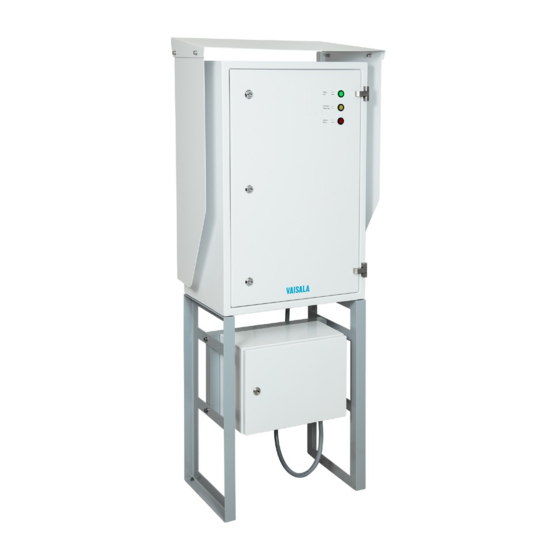
Vaisala Optimus OPT100 User Manual (126 pages)
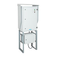
DGA Monitor for power transformers
Table of Contents
-
-
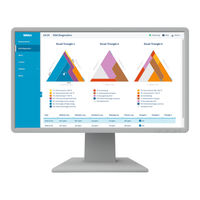
Status Leds23
-
-
-
Alerts Page40
-
Control42
-
Service43
-
Settings45
-
About Page45
-
-
-
Maintenance71
-
Repair73
-
-
-
-
Function Codes104
-
Modbus Registers105
-
Index121
-
Warranty123
-
Recycling123
Advertisement
Vaisala Optimus OPT100 Installation Manual (96 pages)
DGA Monitor for power transformers
Table of Contents

Vaisala Optimus OPT100 User Manual (78 pages)
DGA Monitor for Transformers
Table of Contents
-
-
Status Leds18
-
-
-
Alerts Page27
-
Table27
-
-
-
Maintenance44
-
Repair47
-
-
Advertisement

Vaisala Optimus OPT100 Installation Manual (72 pages)
DGA Monitor for Transformers
Brand: Vaisala
|
Category: Measuring Instruments
|
Size: 4 MB