Vaisala Optimus OPT100 User Manual
Dga monitor for transformers
Hide thumbs
Also See for Optimus OPT100:
- User manual (126 pages) ,
- Installation manual (96 pages) ,
- Installation manual (72 pages)
Table of Contents
Advertisement
Quick Links
Download this manual
See also:
Installation Manual
Advertisement
Table of Contents

Related Manuals for Vaisala Optimus OPT100


Summary of Contents for Vaisala Optimus OPT100
- Page 1 M211858EN-E User Guide Vaisala Optimus ™ DGA Monitor for Transformers OPT100...
- Page 2 Vaisala Oyj Vanha Nurmijärventie 21, FI-01670 Vantaa, Finland P.O. Box 26, FI-00421 Helsinki, Finland +358 9 8949 1 Visit our Internet pages at www.vaisala.com. © Vaisala 2019 users. All legally binding No part of this document may be obligations and agreements are...
-
Page 3: Table Of Contents
Table of Contents Table of Contents About This Document................... 5 Version Information..................5 Related Manuals....................5 Documentation Conventions................6 Trademarks......................6 Product Overview................... 7 Overview of OPT100 DGA Monitor..............7 Basic Features and Options................7 Measured Parameters..................7 2.3.1 Calculating Relative Moisture Saturation Inside Transformer....8 Notes for Normal Operation................ - Page 4 OPT100 User Guide M211858EN-E Maintenance.....................41 Maintenance Safety..................41 Cleaning DGA Monitor..................41 Maintenance....................42 Updating DGA Monitor Software..............42 Starting Autocalibration Manually............... 44 Repair.......................45 4.6.1 Stopping Measurement................45 4.6.2 Turning Off the DGA Monitor for Maintenance........45 4.6.3 Verifying Safety After Repair..............46 4.6.4 Turning On DGA Monitor After Maintenance........
- Page 5 List of Figures List of Figures Figure OPT100 Front Parts with Ground Mounting Set........10 Figure 2 OPT100 Rear Parts with Ground Mounting Set........11 Figure 3 OPT100 Front Parts with Wall Mounting Set..........12 Figure 4 OPT100 Rear Parts with Wall Mounting Set..........13 Figure 5 OPT100 DGA Monitor Cable Glands and Connectors......14 Figure 6...
- Page 6 OPT100 User Guide M211858EN-E List of Tables Table Document Versions (English)................5 Table 2 Related Manuals....................5 Table 3 Measured Parameters..................7 Table 4 Calculated Parameters..................8 Table 5 Meaning of Status LEDs................... 16 Table 6 Modbus RTU Communication Settings............17 Table 7 Modbus TCP Communication Settings............17 Table 8 Data Point Selection Criteria................25...
-
Page 7: About This Document
Chapter 1 – About This Document 1. About This Document 1.1 Version Information Table 1 Document Versions (English) Document Code Date Description M211858EN-E April 2019 This version. Applicable from software version 1.7.0 onwards. Added sections: • Notes for Normal Operation (page 9) • IEC 61850 Protocol (page 18) •... -
Page 8: Documentation Conventions
Indicates that you need to take some notes during the task. 1.4 Trademarks OPTIMUS ™ is a trademark of Vaisala Oyj. All other product or company names that may be mentioned in this publication are trade names, trademarks, or registered trademarks of their respective owners. -
Page 9: Product Overview
Chapter 2 – Product Overview 2. Product Overview 2.1 Overview of OPT100 DGA Monitor OPT100 is a device for monitoring the internal condition of an electrical transformer using dissolved gas analysis (DGA), also known as fault gas analysis. OPT100 is intended to be installed next to the transformer, and connected to it by two oil lines. -
Page 10: Calculating Relative Moisture Saturation Inside Transformer
OPT100 User Guide M211858EN-E Parameter Output Unit(s) Description Ethylene (C Measured from extracted gas Acetylene (C Measured from extracted gas Carbon monoxide (CO) Measured from extracted gas Carbon dioxide (CO Measured from extracted gas Hydrogen (H Measured in-oil Moisture (H and %RS Measured in-oil as relative saturation (%RS). -
Page 11: Notes For Normal Operation
Temperature at location where new relative moisture saturation is needed at -1662.70 A is a water solubility coefficient. Vaisala uses this standard value in all of its oil moisture transmitters. You can also use this equation with an oil-specific coefficient if it has been determined for your oil. -
Page 12: Parts With Ground Mounting Set
OPT100 User Guide M211858EN-E 2.5 Parts with Ground Mounting Set Figure 1 OPT100 Front Parts with Ground Mounting Set Status LEDs OPT100 DGA Monitor Door lock (3 pcs) Power supply unit Door lock Mounting stand Wedge anchors (6 pcs) -
Page 13: Figure 2 Opt100 Rear Parts With Ground Mounting Set
Chapter 2 – Product Overview Figure 2 OPT100 Rear Parts with Ground Mounting Set Weather shield Cable glands and oil connections for DGA Monitor Cable glands for power supply unit... -
Page 14: Parts With Wall Mounting Set
OPT100 User Guide M211858EN-E 2.6 Parts with Wall Mounting Set Figure 3 OPT100 Front Parts with Wall Mounting Set Status LEDs OPT100 DGA Monitor Door lock (3 pcs) Power supply unit Door lock... -
Page 15: Figure 4 Opt100 Rear Parts With Wall Mounting Set
Chapter 2 – Product Overview Figure 4 OPT100 Rear Parts with Wall Mounting Set Installation beam (upper) Weather shield Installation beam (lower) Cable glands for DGA Monitor Cradle for power supply unit Cable glands for power supply unit... -
Page 16: Cable Glands And Connectors
OPT100 User Guide M211858EN-E 2.7 Cable Glands and Connectors Figure 5 OPT100 DGA Monitor Cable Glands and Connectors Oil Out: connection for oil return line Oil In: connection for oil intake Ground terminal RS-485: cable gland for RS-485 connection Relay control out: cable gland for relay control to power supply unit DC in: 24 VDC connection from power supply unit Ethernet: external RJ45 connector for permanent Ethernet connection Figure 6 OPTPSU1 Power Supply Unit Cable Glands and Connectors... -
Page 17: Interior Parts
Chapter 2 – Product Overview 2.8 Interior Parts Figure 7 Inside OPT100 DGA Monitor Enclosure Valve 5 (bleed valve). Must be manually accessed during initialization and uninstallation. Valve 4 Oil block Valve 3 Valve 2 Valve 1 In-oil measurement of hydrogen and moisture Oil out Oil in... -
Page 18: Status Leds
OPT100 User Guide M211858EN-E Figure 8 Inside OPTPSU1 Power Supply Unit Enclosure Circuit breaker for AC power (F1) Surge arresters Power switch (S1) Power supply Relays (3 pcs). Each relay has a LED that is lit when the relay is active. DC OK LED. -
Page 19: Gas Level Alerts
Chapter 2 – Product Overview 2.10 Gas Level Alerts DGA monitor has individual gas level alerts for measured gases and total dissolved combustible gases (TDCG). Each gas has four possible alerts (latest measured value, ROC 1 day, ROC 7 days, ROC 30 days) and two separate limits (caution and alarm). Additionally, moisture alerts (ppm and %RS) can be configured for latest measured values. -
Page 20: Dnp3 Protocol
2.13 IEC 61850 Protocol IEC 61850 protocol is an optional feature and requires a license. If a license is not installed on the DGA monitor, you cannot enable the protocol. Contact Vaisala for acquiring the license. Data measured by DGA monitor can be read using IEC 61850 protocol over the external Ethernet connection. -
Page 21: User Interface
Chapter 3 – User Interface 3. User Interface 3.1 Overview of User Interface DGA monitor runs a web server on its processing unit. This web server provides the user interface of the DGA monitor. The user interface can be accessed through Ethernet using a standard web browser;... - Page 22 OPT100 User Guide M211858EN-E 3. Choose the appropriate user level: • Select Admin to perform installation and maintenance tasks. • Select User to view data without making changes to the system. 4. If logging in as Admin, enter the unique admin password for this OPT100 DGA Monitor. The password is included in the OPT100 delivery documentation.
-
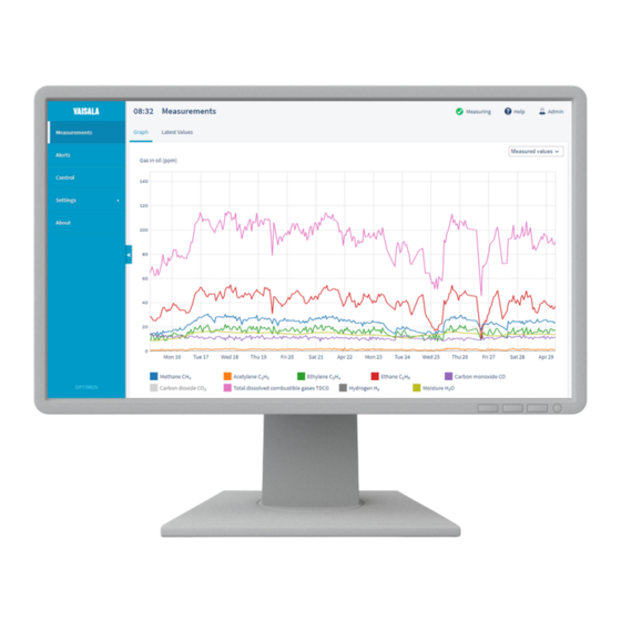
Page 23: Measurements Page
Chapter 3 – User Interface 3.1.2 Measurements Page Measurements page provides the measurement data in graph and table format. Figure 10 Measurement Graph Pop-up that shows the values at the point below the cursor. Graph area. Use the mouse wheel to adjust the zoom level of the y-axis. Quick selection buttons for preset time windows. -
Page 24: Figure 11 Measurement Graph For 1 Day Rate Of Change Values
OPT100 User Guide M211858EN-E Figure 11 Measurement Graph for 1 Day Rate of Change Values... -
Page 25: Dga Diagnostics Page
Customer or any other user of such data. The use and/or application of any such data shall be at the sole risk and liability of the Customer or the user. DGA Diagnostics is an optional feature and requires a license. Contact Vaisala for acquiring the license. -
Page 26: Figure 13 Duval Triangles On The Dga Diagnostics Page
OPT100 User Guide M211858EN-E Figure 13 Duval Triangles on the DGA Diagnostics Page DGA Diagnostics page shows the progression of selected data points from the past year overlaid on top of Duval triangles: • Triangle 1: Classic Duval triangle for DGA in oil-filled transformers using methane, ethylene, and acetylene •... -
Page 27: Alerts Page
Chapter 3 – User Interface The data points are 24 hour average values for the included gases and must meet the following criteria for each point: • At least 5 reliable measurement points must exist in the previous 24 hours. Reliability criteria are the same as for gas alert functionality. -
Page 28: Control Page
OPT100 User Guide M211858EN-E You can configure gas level alerts on the Alerts page. There are separate rows for each individual alert that you can configure. By default, all alerts are off, and automatic acknowledgement is off. 3.1.5 Control Page Control page shows the current status of the DGA monitor and contains the controls for initialization, starting and stopping the measurement, and uninstalling the DGA monitor. -
Page 29: Settings
About page shows the serial number and software version of the DGA monitor. There are also two buttons: • Update starts the software update. To update the software version of the DGA monitor, you need a software update file from Vaisala. -
Page 30: Messages
Generating the file may take up to 30 minutes. Select Download Data to retrieve the file. The diagnostic data in the file is intended for use only by Vaisala. Figure 17 About Page 3.1.8 Messages User interface of the DGA monitor will display important information as messages at the top of the user interface. -
Page 31: Status Indicator
Chapter 3 – User Interface Figure 18 Gas Level Alert Message Active 3.1.9 Status Indicator Current status of the DGA monitor is shown on top of the user interface. Table 9 System Statuses Status Text Meaning Initializing DGA monitor is being initialized. Initialization is a part of installation and requires physical access inside the DGA monitor enclosure. -
Page 32: Starting Measurement
OPT100 User Guide M211858EN-E Status Text Meaning Stopping Normal measurement is being stopped. When complete, the DGA monitor will remain in the standby state. Caution Gas alert caution limit exceeded. Gas Alarm Gas alert alarm limit exceeded. Error Device error has been detected. Measurement cycles are not being performed. -
Page 33: Configuring Gas Level Alerts
Chapter 3 – User Interface 3.3 Configuring Gas Level Alerts Figure 19 Alerts Page You can configure gas level alerts on the Alerts page. There are separate rows for each individual alert that you can configure. By default, all alerts are off, and automatic acknowledgement is off. -
Page 34: Acknowledging Gas Level Alerts
OPT100 User Guide M211858EN-E 4. For each alert you want to configure, enter the a. Enter the Caution Limit in ppm. This is the lower limit that triggers an alert with caution severity. b. Enter the Alarm Limit. Alarm limit should be higher than the caution limit. c. -
Page 35: Setting Date And Time
Chapter 3 – User Interface Figure 20 Alert Screen with Methane Caution Alert Visible 3.5 Setting Date and Time Figure 21 Date and Time Settings Page... - Page 36 OPT100 User Guide M211858EN-E DGA monitor uses UTC (Coordinated Universal Time) internally. Time and time stamps in the user interface are shown according to the time zone of the connecting web browser. 1. Connect to the user interface as the Admin user. See Connecting to User Interface (page 19).
-
Page 37: Changing Administrator Password
Chapter 3 – User Interface 3.6 Changing Administrator Password Figure 22 Changing Administrator Password 1. Connect to the user interface as the Admin user. See Connecting to User Interface (page 19). 2. In the top right corner of the user interface, select Admin > Change password. 3. -
Page 38: Configuring Serial Line And Modbus Rtu
OPT100 User Guide M211858EN-E 3.7 Configuring Serial Line and Modbus RTU Figure 23 Modbus RTU Settings Page This procedure configures the settings of the RS-485 line and the Modbus RTU protocol. 1. Connect to the user interface as the Admin user. See Connecting to User Interface (page 19). -
Page 39: Configuring Network Connection
Chapter 3 – User Interface 3.8 Configuring Network Connection Figure 24 IP Address Settings Page This procedure configures the network settings of the external Ethernet connection. 1. Connect to the user interface as the Admin user. See Connecting to User Interface (page 19). -
Page 40: Configuring Dnp3 Protocol
OPT100 User Guide M211858EN-E 3.9 Configuring DNP3 Protocol Figure 25 DNP3 Settings Page 1. Connect to the user interface as the Admin user. See Connecting to User Interface (page 19). 2. In the user interface, select Settings > Network > DNP3. 3. Select if the DNP3 protocol should be Enabled or Disabled. 4. -
Page 41: Configuring Iec 61850 Protocol
Figure 26 IEC 61850 Settings Page IEC 61850 protocol is an optional feature and requires a license. If a license is not installed on the DGA monitor, you cannot enable the protocol. Contact Vaisala for acquiring the license. 1. Connect to the user interface as the Admin user. See... -
Page 42: Configuring Relays
OPT100 User Guide M211858EN-E 3.11 Configuring Relays Figure 27 Relay Settings Page 1. Connect to the user interface as the Admin user. See Connecting to User Interface (page 19). 2. In the user interface, select Settings > Relays. 3. Each of the three relays is configured individually. For each relay: a. -
Page 43: Maintenance
Chapter 4 – Maintenance 4. Maintenance 4.1 Maintenance Safety WARNING! Keep away from live circuits. Operating personnel must observe safety regulations at all times. WARNING! Ground the DGA monitor enclosures as instructed in the wiring instructions. Verify the grounding before and after performing maintenance on the unit. -
Page 44: Maintenance
These updates are only applied to new measurement cycles after the update, which may cause some discontinuity in the measured gas levels even if the concentration of gases in the measured oil has not changed. Vaisala recommends starting autocalibration manually after a software update. -
Page 45: Figure 28 About Screen With Current Software Version And Update Button
Chapter 4 – Maintenance Figure 28 About Screen with Current Software Version and Update Button 1. Connect to the user interface as the Admin user. See Connecting to User Interface (page 19). 2. Switch the DGA monitor to Standby mode. See Stopping Measurement (page 45). -
Page 46: Starting Autocalibration Manually
OPT100 User Guide M211858EN-E 6. Select Upload to send the file to the DGA monitor. 7. DGA monitor will verify that the file was received successfully, and start the update. The update will take several minutes. Do not power off or attempt to operate the DGA monitor during the update. -
Page 47: Repair
OPT100 product page http://www.vaisala.com/opt100 for updates. • If a repair procedure you need is not available in the documentation, contact Vaisala for assistance. • Some repairs can only be performed by a Vaisala representative. • For any components included inside the OPT100 DGA Monitor or the OPTPSU1 power supply unit, use only spare parts supplied by Vaisala. -
Page 48: Verifying Safety After Repair
OPT100 User Guide M211858EN-E 4.6.3 Verifying Safety After Repair Go through the following verification steps after performing repairs on the DGA monitor. 1. If you have replaced or altered any mechanical parts of the DGA monitor enclosure or mounting accessories, verify that: •... -
Page 49: Starting Measurement
Chapter 4 – Maintenance 4.6.5 Starting Measurement In normal operation DGA monitor repeats the measurement cycle continuously. You can only start the measurement if DGA monitor is currently in standby. 1. Connect to the DGA monitor user interface and log in as an Admin user. 2. - Page 50 OPT100 User Guide M211858EN-E 5. When instructed to do so, remove the pipe plug from the bleed valve. Select Continue when done. 6. When instructed to do so, close the oil intake and return valves on the transformer. 7. Disconnect oil pipes from the Oil In and Oil Out connections on the outside of the DGA monitor.
- Page 51 Chapter 4 – Maintenance 10. Push in the gray knob on the side of the bleed valve, and turn it 90° clockwise to lock the valve manually. Select Continue when done. 11. Select OK when the uninstallation sequence has completed. 12.
-
Page 52: Troubleshooting
OPT100 User Guide M211858EN-E 5. Troubleshooting 5.1 Problem Situations Table 10 Troubleshooting Table Problem Possible Cause Solution Green status LED is flashing. DGA monitor is in standby Start the measurement mode. mode. Starting Measurement (page 30). Yellow status LED is lit. DGA monitor has been installed Perform commissioning and but not initialized. -
Page 53: Resolving A Device Error
Chapter 5 – Troubleshooting 5.2 Resolving a Device Error Figure 29 Device Error Active If the DGA monitor has a serious hardware problem or cannot measure due to some external cause, it will automatically stop trying to run the measurement cycles. The red status LED on the door will be lit, and the user interface will show an appropriate message. - Page 54 OPT100 User Guide M211858EN-E 7. If the device error is not resolved after a couple of attempts, contact Vaisala support. From the About page of the user interface you can create a diagnostic data file that can help Vaisala diagnose the device error. It is recommended that you do this if your DGA monitor stops due to a device error, regardless of if the error was successfully resolved.
-
Page 55: Technical Data
Chapter 6 – Technical Data 6. Technical Data 6.1 OPT100 Technical Specification Table 11 Measured Parameters in Oil Parameter Range 1) 2) Accuracy Repeatability Methane (CH 0 ... 10 000 ppm 10 ppm or 10 % of 10 ppm or 5 % of reading reading Ethane (C 0 ... -
Page 56: Table 13 Calculated Parameters
OPT100 User Guide M211858EN-E Property Description Initialization time to full accuracy Two days Data storage At least 10 years Expected operating life > 15 years Three cycles for ethane and hydrogen. Table 13 Calculated Parameters Property Description Total dissolved combustible gases Combined total of H , CO, CH , and C... -
Page 57: Table 15 Power Supply
Chapter 6 – Technical Data Property Description Storage temperature range -40 ... +60 °C (-40 ... +140 °F) The fire point [of transformer oil] is normally approximately 10 °C [18 °F] higher than the closed flash point. See, for example, Heathcote, Martin J. The J & P Transformer Book. 13th ed. -
Page 58: Table 17 Mechanical Specifications
OPT100 User Guide M211858EN-E Property Description Relay Outputs Number of relays 3 pcs, normally open (NO) or normally closed (NC), user selectable Trigger type Gas alert with user selectable limits Connector Screw terminals (inside power supply unit housing) Wire size 0.5 ... 4 mm (20 ... -
Page 59: Table 18 Type Tests
Chapter 6 – Technical Data Property Description OPT100 DGA Monitor 35 kg (77 lb) OPTPSU1 Power Supply Unit 12 kg (27 lb) OPTMSET1 Wall mounting set 8 kg (18 lb) OPTMSET2 Ground mounting set 16 kg (35 lb) OPTSHLD1 Weather shield 6 kg (13 lb) Materials OPT100 DGA Monitor housing... -
Page 60: Opt100 Spare Parts And Accessories
OPT100 User Guide M211858EN-E Category Standard Class/Level Test IEC60068-2-30 +40 °C (+104 °F), 85 Damp heat, cyclic IEC60068-2-32 Drop tolerance SFS-EN ISO +40 °C / 100 %RH for Constant humidity 6270-1:2017 480 h condensation atmosphere (C5‑M class) SFS-ISO 9227:2017 Neutral Salt Spray Salt fog (C5‑M class) (NSS), 35 °C, 5 %, PH 6-7, 1000 h... -
Page 61: Opt100 Dimensions With Ground Mounting Set
Chapter 6 – Technical Data 6.3 OPT100 Dimensions with Ground Mounting [in] [0.79] 510 [20.08] 675 [26.57] 453 [17.83] 550 [21.65] 400 [15.75] 350 [13.78] Figure 30 Dimensions with Ground Mounting Set... -
Page 62: Appendix A: Modbus Reference
OPT100 User Guide M211858EN-E Appendix A. Modbus Reference A.1 Default Communication Settings Table 21 Default Modbus Serial Communication Settings Description Default Value Serial bit rate 19200 Number of data bits Parity Number of stop bits Modbus slave ID A.2 Function Codes Table 22 Supported Function Codes Function Code (Decimal) Function Code (Hexadecimal) Name... -
Page 63: 32-Bit Floating Point Format
Appendix A – Modbus Reference A.3.1 32-Bit Floating Point Format Least-significant 16 bits of floating point or integer numbers are placed at the smaller Modbus address as specified in Open Modbus TCP Specification, Release 1.0. This is also known as "little-endian" or "Modicon" word order. The CDAB byte order is used. Floating point values are represented in standard IEEE 32-bit floating point format. - Page 64 OPT100 User Guide M211858EN-E Register Number Address Register Data Format Unit and Notes (Decimal) (Hexadecimal) Description 001E Carbon dioxide 32-bit float 0020 Total dissolved 32-bit float combustible gases (TDCG) 0022 Hydrogen 32-bit float 0024 Moisture in oil 32-bit float 0026 Temperature of 32-bit float °C...
- Page 65 Appendix A – Modbus Reference Register Number Address Register Data Format Unit and Notes (Decimal) (Hexadecimal) Description 0052 Acetylene 32-bit float 0054 Ethylene 32-bit float 0056 Ethane 32-bit float 0058 Carbon monoxide 32-bit float 005A Carbon dioxide 32-bit float 005C Total dissolved 32-bit float combustible...
-
Page 66: Alert Registers
OPT100 User Guide M211858EN-E Register Number Address Register Data Format Unit and Notes (Decimal) (Hexadecimal) Description Gas Ratios (24h Average Values) 008C 32-bit float 008E 32-bit float 0090 32-bit float 0092 32-bit float 0094 32-bit float 0096 32-bit float Other 00A0 Time stamp of 64-bit float... -
Page 67: Table 24 Alert Registers (Read-Only)
Appendix A – Modbus Reference Table 24 Alert Registers (Read-Only) Register Number Address Register Data Format Bit Order (Decimal) (Hexadecimal) Description 000A Gas level caution 16-bit field 0 = Methane alerts for present 1 = Acetylene values 2 = Ethylene 3 = Ethane 4 = Carbon monoxide 5 = Carbon... - Page 68 OPT100 User Guide M211858EN-E Register Number Address Register Data Format Bit Order (Decimal) (Hexadecimal) Description 000D Gas level ROC 16-bit field 0 = Methane caution alerts for 1 = Acetylene one month 2 = Ethylene average values 3 = Ethane 4 = Carbon monoxide 5 = Carbon...
-
Page 69: Test Value Registers
Appendix A – Modbus Reference Register Number Address Register Data Format Bit Order (Decimal) (Hexadecimal) Description 0010 Gas level ROC 16-bit field 0 = Methane alarms for one 1 = Acetylene week average 2 = Ethylene values 3 = Ethane 4 = Carbon monoxide 5 = Carbon... -
Page 70: Modbus Communication Examples
OPT100 User Guide M211858EN-E Register Number Address Data Format Test value (Decimal) (Hexadecimal) 00D6 32-bit float 1.23456 00D8 64-bit float 1.23456789 A.4 Modbus Communication Examples Reading Acetylene Value Device address used in the following examples is 240 (F0 The values returned by the device differ depending on the measurement conditions. - Page 71 Appendix A – Modbus Reference Response Value of first register (least significant word) Value of second register (most significant word) Modbus RTU checksum (silence for >3.5 bytes) End of Modbus RTU frame Communication Description Register address 23 (1-based Modbus documentation format) = 0016 (0-based format used in actual communication).
- Page 72 OPT100 User Guide M211858EN-E...
-
Page 73: Index
Index Index turning off..........45 accessories..........58 turning on..........46 autocalibration measured parameters......7 starting............ 44 measurement..........21 starting..........30, 47 stopping..........45 calculated parameters......7 messages cleaning............41 errors............28 gas level alerts........28 Modbus protocol.......17, 36 date and time........... 33 communication examples....68 device error..........51 function codes........60 DGA diagnostics gas level alerts........ - Page 74 OPT100 User Guide M211858EN-E safety............ 41, 46 serial line............ 36 software update........42 spare parts..........58 standby mode.......... 45 starting measurement....30, 47 status indicator........29 status LEDs..........16 stopping measurement......45 technical specification......53 troubleshooting........50 turning off..........45 turning on..........46 uninstalling..........47 user interface..........19 about page..........
-
Page 75: Technical Support
Technical Support Contact Vaisala technical support at helpdesk@vaisala.com. Provide at least the following supporting information: • Product name, model, and serial number • Name and location of the installation site • Name and contact information of a technical person who can provide further information on the problem For more information, see www.vaisala.com/support. - Page 76 OPT100 User Guide M211858EN-E...
- Page 78 www. v aisala.com...
Need help?
Do you have a question about the Optimus OPT100 and is the answer not in the manual?
Questions and answers