Vaisala Optimus OPT100 Installation Manual
Dga monitor for power transformers
Hide thumbs
Also See for Optimus OPT100:
- User manual (126 pages) ,
- Installation manual (72 pages) ,
- User manual (78 pages)

Related Manuals for Vaisala Optimus OPT100


Summary of Contents for Vaisala Optimus OPT100
- Page 1 M211857EN-R Installation Guide Vaisala Optimus ™ DGA Monitor for power transformers OPT100...
- Page 2 This product contains software developed disclosed to a third party without prior by Vaisala or third parties. Use of the written permission of the copyright holder. software is governed by license terms and Translated documents and translated...
-
Page 3: Table Of Contents
Table of contents Table of contents About this document..................7 Version information..................7 Related manuals....................7 Documentation conventions................8 Trademarks......................8 Planning the installation................10 Installation safety.................... 10 Installation phases.................... 11 Required personnel..................11 Required materials..................12 Recommended tools..................13 Storing and transporting DGA monitor............14 Reinstalling DGA monitor................14 Installation site requirements................ - Page 4 OPT100 Installation Guide M211857EN-R Connecting relays...................54 4.10 Connecting auxiliary communication devices..........57 4.11 Connecting mains power................59 4.12 Verifying tightness of cable glands..............63 Commissioning....................65 Turning on DGA monitor................65 Connecting to user interface.................65 Changing administrator password............... 66 Configuring network connection..............67 Configuring user interface security..............68 Setting device name..................
- Page 5 List of figures List of figures Figure Possible locations of oil connections............17 Figure 2 Assembly of the mounting stand..............21 Figure 3 Anchoring holes on the mounting stand..........22 Figure 4 OPT100 front parts with Ground Mounting Set........23 Figure 5 OPT100 rear parts with Ground Mounting Set........
- Page 6 OPT100 Installation Guide M211857EN-R List of tables Table 1 Document versions (English)................7 Table 2 Related manuals....................8 Table 3 Terminal block Y3 wiring................. 44 Table 4 Terminal block X5 wiring................. 46 Table 5 Terminal block Y2 wiring..................47 Table 6 Terminal block X4 wiring.................
-
Page 7: About This Document
Chapter 1 – About this document 1. About this document 1.1 Version information This document provides installation instructions for Vaisala Optimus ™ DGA Monitor OPT100. Table 1 Document versions (English) Document code Date Description M211857EN-R October 2022 Applicable from software version 1.17.0 onwards. -
Page 8: Documentation Conventions
Tip gives information for using the product more efficiently. Lists tools needed to perform the task. Indicates that you need to take some notes during the task. 1.4 Trademarks Vaisalaâ is a registered trademark of Vaisala Oyj. OPTIMUS ™ is a trademark of Vaisala Oyj. - Page 9 Chapter 1 – About this document Modbusâ is a registered trademark of Schneider Automation Inc. Chrome ™ is a trademark of Google Inc. Firefoxâ is a registered trademark of Mozilla Foundation. Microsoftâ and Edgeâ are either registered trademarks or trademarks of Microsoft Corporation in the United States and/or other countries.
-
Page 10: Planning The Installation
OPT100 Installation Guide M211857EN-R 2. Planning the installation 2.1 Installation safety WARNING! Read the product documentation carefully before installing or operating the product. If you encounter the following marking during installation or operation, consult product documentation to find out the nature of the potential hazards and any actions which have to be taken to avoid them: WARNING! Only licensed experts may install electrical components. -
Page 11: Installation Phases
Chapter 2 – Planning the installation CAUTION! Surfaces inside DGA monitor that are marked with the symbol below heat up during normal operation. Avoid touching hot surfaces and wear protective gloves when working inside the cabinet. Whenever possible, allow the DGA monitor to cool down before starting the work. Wear protective eyewear and gloves. -
Page 12: Required Materials
Applicable legislation and site safety guidelines may require additional personnel to be present in the installation. 2.4 Required materials In addition to the items delivered by Vaisala, installation of the DGA monitor requires various materials that you must supply yourself. Items delivered by Vaisala •... -
Page 13: Recommended Tools
• Adapters for connecting the oil pipes to the DGA monitor, if not using the recommended tubing size (10‑mm (0.39‑in) outer diameter). Optional accessories for connecting 3/8" and 1/4" outer diameter tubing are available from Vaisala. • Pipe fittings for joining pipe sections •... -
Page 14: Storing And Transporting Dga Monitor
OPT100 Installation Guide M211857EN-R • Wrenches of various sizes • Socket wrench and socket set • Allen keys • Cutting tools • Cable stripping tool • Metal file • Measuring tape • Impact drill and bits • Spirit level • Multimeter Tools for oil pipe construction •... -
Page 15: Installation Location Of Dga Monitor
• Operating altitude: DGA monitor is intended for use in altitude range -1000 … 3000 m. If you have any questions, contact Vaisala for more information. Performing a site inspection in person is a good idea. Take photographs of the intended installation location, oil connections, and electrical connections. - Page 16 OPT100 Installation Guide M211857EN-R • The recommended arrangement is to use two valves in different locations on the transformer. This improves oil circulation inside the transformer and prevents the returned oil from immediately mixing with the next sample. • Use the same valve for oil intake that has been previously used to take oil samples. This makes the measurements results of the DGA monitor more comparable with previous laboratory analysis results.
-
Page 17: Figure Possible Locations Of Oil Connections
Chapter 2 – Planning the installation Figure 1 Possible locations of oil connections Oil reservoir. Do not use. Side of the oil tank, top level. Suitable location for oil connection if the valve is under oil level at all times. Side of the oil tank, high enough from the bottom to enable proper oil movement. Suitable location for oil connection. -
Page 18: Network Security
OPT100 Installation Guide M211857EN-R 2.8.4 Network security DGA monitor is intended to be connected to a secure SCADA network that is appropriately protected against security threats. Do not connect the DGA monitor directly to the Internet. The second Ethernet port of the DGA monitor (marked ETH1) is for temporary local use only. 2.9 Regulatory compliances OPT100 Optimus DGA monitor is in conformity with the provisions of the following EU directives:... -
Page 19: Canada Ices-003 Compliance Statement
Chapter 2 – Planning the installation 2.9.2 Canada ICES-003 compliance statement This Class A digital apparatus complies with Canadian ICES‑003. Cet appareil numerique de la classe A est conforme a la norme NMB‑003 du Canada. -
Page 20: Mechanical Installation
3.2 Mounting with Ground Mounting Set • Ground Mounting Set (Vaisala item OPTMSET2) • Mounting stand (delivered in three parts) • Wedge anchors (6 pcs) for securing the mounting stand to ground •... -
Page 21: Figure 2 Assembly Of The Mounting Stand
Chapter 3 – Mechanical installation Figure 2 Assembly of the mounting stand Mounting holes on the top are for attaching the DGA monitor. Mounting holes on the side join the parts of the mounting stand together. Holes on the bottom (three on each side) are for anchoring the mounting stand to the ground. -
Page 22: Figure 3 Anchoring Holes On The Mounting Stand
OPT100 Installation Guide M211857EN-R 2. Using the assembled mounting stand as the template, mark the locations of the six anchors on the mounting surface. If the mounting location is at the edge of a concrete slab, leave at least 10 cm (4 in) clearance to the edge. 510 [20.08] [in] Figure 3 Anchoring holes on the mounting stand... -
Page 23: Parts With Ground Mounting Set
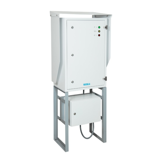
Chapter 3 – Mechanical installation 3.2.1 Parts with Ground Mounting Set Figure 4 OPT100 front parts with Ground Mounting Set Status LEDs OPT100 DGA Monitor Door lock (3 pcs) Power supply unit (OPTPSU) Door lock Mounting stand Wedge anchors (6 pcs) -
Page 24: Figure 5 Opt100 Rear Parts With Ground Mounting Set
OPT100 Installation Guide M211857EN-R Figure 5 OPT100 rear parts with Ground Mounting Set Weather shield Cable glands and oil connections for DGA Monitor Cable glands for power supply unit... -
Page 25: Dimensions With Ground Mounting Set
Chapter 3 – Mechanical installation 3.2.2 Dimensions with Ground Mounting Set [in] [0.79] 510 [20.08] 675 [26.57] 453 [17.83] 550 [21.65] 400 [15.75] 350 [13.78] Figure 6 OPT100 dimensions with Ground Mounting Set... -
Page 26: Mounting With Wall Mounting Set
OPT100 Installation Guide M211857EN-R 3.3 Mounting with Wall Mounting Set • Wall Mounting Set (Vaisala item OPTMSET1) • Installation beam (2 pcs) • Cradle for Power Supply Unit • Screws and washers • M8 anchors or bolts (suitable for wall material) •... - Page 27 Chapter 3 – Mechanical installation 6. Add a second screw (with washer) below each of the installed screws, and tighten them. The cabinet is now secured to the installation beams by a total of eight screws. Installation beam mounting screws. Leave second set of mounting holes free for weather shield installation.
-
Page 28: Parts With Wall Mounting Set
OPT100 Installation Guide M211857EN-R 3.3.1 Parts with Wall Mounting Set Figure 7 OPT100 front parts with Wall Mounting Set Status LEDs OPT100 DGA Monitor Door lock (3 pcs) Power supply unit Door lock... -
Page 29: Figure 8 Opt100 Rear Parts With Wall Mounting Set
Chapter 3 – Mechanical installation Figure 8 OPT100 rear parts with Wall Mounting Set Installation beam (upper) Weather shield Installation beam (lower) Cable glands for DGA Monitor Cradle for power supply unit Cable glands for power supply unit... -
Page 30: Dimensions With Wall Mounting Set
OPT100 Installation Guide M211857EN-R 3.3.2 Dimensions with Wall Mounting Set [in] 675 [26.57] 467 [14.45] 550 [21.65] 400 [15.75] Figure 9 OPT100 dimensions with Wall Mounting Set... -
Page 31: Figure 10 Mounting Dimensions Of Installation Beams
Chapter 3 – Mechanical installation [in] Ø 8.50 holes for M8 anchors or bolts Installation beam symmetry lines Figure 10 Mounting dimensions of installation beams... -
Page 32: Installing Oil Lines
(10‑mm (0.39‑in) outer diameter). Optional accessories for connecting 3/8" and 1/4" outer diameter tubing are available from Vaisala. • Recommended oil pipe material: stainless steel tubing with 10‑mm (0.39‑in) outer diameter and 1 … 1.5‑mm (0.039 … 0.059 in) wall thickness. Enough to connect the oil intake and return valves to the DGA monitor. - Page 33 Chapter 3 – Mechanical installation 1. Inspect and prepare the selected inlet and outlet oil valves on the transformer: a. Remove any previously installed flow direction control valves. The DGA monitor needs to pump oil in both directions during initialization, and will not work if there are flow direction controllers in the oil lines.
-
Page 34: Figure 11 Pipe Or Hose Connection Fitting Order
OPT100 Installation Guide M211857EN-R 9. Connect both oil lines to the fittings on the DGA monitor. Use the supplied Swagelokâ adapters (delivered in a separate bag). a. Insert the nut of the adapter over the oil pipe or hose. b. Insert the two ferrules over the pipe or hose. Make sure they are in the order and orientation shown in Figure 11 (page 34). -
Page 35: Installing Oil Lines With Flexible Hoses
• 14‑mm wrench (2 pcs) • 19‑mm wrench • 22‑mm wrench • Flex hose kit, 2 x 10 m (Vaisala item ASM214666SP) • Adapter kit, ½" NPT (Vaisala item ASM214667SP) • Adapter kit, 1" NPT (Vaisala item ASM214668SP) • Adapter kit, 2" NPT (Vaisala item ASM214669SP) •... - Page 36 OPT100 Installation Guide M211857EN-R If the DGA monitor is mounted using the wall mounting set, the power supply unit will be attached by a mounting cradle. Make sure you are not routing the oil lines so that they will obstruct the power supply unit attachment. Before starting to install the oil lines, see oil connection location recommendations for important information.
-
Page 37: Attaching Power Supply Unit
Support the power supply unit and cradle and attach them to the bottom of the OPT100 cabinet. More information ‣ Installing oil lines with flexible hoses (page 35) 3.6 Attaching weather shield • Weather Shield (Vaisala item OPTSHLD1) • Weather shield (delivered in three parts) • Screws and washers... - Page 38 OPT100 Installation Guide M211857EN-R 1. Attach the weather shield to the OPT100 cabinet: a. Attach the left side panel. Note that the panels have an assigned side, they are not identical. b. Attach the right side panel. c. Verify that all screws holding the side panels of the weather shield are tight. d.
-
Page 39: Electrical Installation
RS-485 RS-485 connection. 5 … 10 mm 20 mm (0.20 … 0.39 in) Relay control Relay control to OPTPSU. Use Vaisala cable 7 … 12 mm 24 mm CBL210539. (0.28 … 0.47 in) DC in DC input from OPTPSU. Use Vaisala cable 9 …... -
Page 40: Optpsu Cable Glands And Connectors
OPT100 Installation Guide M211857EN-R 4.2 OPTPSU cable glands and connectors Figure 13 Cable glands and connectors on OPTPSU power supply unit Label Description Cable diameter Wrench size Ground connection. 13 mm 4 … 16 mm (12 … 5 AWG) conductor AC in Mains power input. -
Page 41: Interior Parts
(0.28 … 0.47 in) DC out DC output to DGA monitor, 24 V DC, 20 A. 9 … 16 mm 30 mm Use Vaisala cable CBL210544. (0.35 … 0.63 in) 4.3 Interior parts Figure 14 Inside DGA monitor cabinet Valve 5 (bleed valve). Must be manually accessed during initialization and uninstallation. -
Page 42: Grounding Dga Monitor
OPT100 Installation Guide M211857EN-R Figure 15 Inside Power Supply Unit cabinet (OPTPSU1 and OPTPSU2) Circuit breaker for AC or DC power (F1) Surge arresters Power switch (S1) Power supply Relays (3 pcs). Each relay has a LED that is lit when the relay is active. DC OK LED. -
Page 43: Connecting Optpsu Power To Dga Monitor
• Screwdriver with 3-mm-wide (0.12‑in) slotted head • Adjustable wrench CAUTION! If the Vaisala-supplied instrument power cable is not available, use a shielded cable with 6 mm (10 AWG) wires. Maximum length of the cable is 1.2 m (3 ft 11 in). -
Page 44: Figure 16 Terminal Block Y3 Wiring
M211857EN-R 5. Inside the DGA monitor, connect the wires to terminal block Y3: Table 3 Terminal block Y3 wiring Signal Wire color Terminal Vaisala cable CBL210544 24 V DC + Black with red marking 24 V DC − Black − Ground Green/yellow −... - Page 45 Chapter 4 – Electrical installation 8. Bend the cable braid over the seal insert so that it will make contact with metal when the cable gland is tightened. 9. Push the outer nut and the seal insert against the contact socket of the gland and tighten the outer nut.
-
Page 46: Connecting Relay Control To Power Supply Unit
Green/yellow Figure 17 Terminal block X5 wiring 4.6 Connecting relay control to power supply unit • Relay control cable (marked RELAY, Vaisala cable CBL210539) • Screwdriver with 3-mm-wide (0.12‑in) slotted head • Adjustable wrench 1. Open the cable gland marked Relay control out on the DGA monitor. Remove the plug and store it for later use. -
Page 47: Figure 18 Terminal Block Y2 Wiring
5. Inside the DGA monitor, connect the wires to terminal block Y2: Table 5 Terminal block Y2 wiring Signal Wire color Terminal Vaisala cable CBL210539 Relay 1 control + White Relay 1 control − Brown Relay 2 control + Green Relay 2 control −... -
Page 48: Figure 19 Terminal Block X4 Wiring
10. Inside the power supply unit, connect the wires to terminal block X4: Table 6 Terminal block X4 wiring Signal Wire color Terminal Vaisala cable CBL210539 Relay 1 control + White Relay 1 control − Brown Relay 2 control + Green Relay 2 control −... -
Page 49: Connecting Rs-485 Serial Line
Chapter 4 – Electrical installation 4.7 Connecting RS-485 serial line • RS-485 cable • Screwdriver with 3-mm-wide (0.12‑in) slotted head • Cable stripping tool Default settings of the RS-485 line are; • Baud rate: 19200 • Transmission mode: 8E1 • Modbus slave ID: 240 1. -
Page 50: Figure 20 Terminal Block Y1 Wiring Example
OPT100 Installation Guide M211857EN-R 5. Inside the DGA monitor, connect the wires to terminal block Y1: Verify the wiring colors of your cable before making any connections. Table 7 Terminal block Y1 wiring Signal Terminal RS-485 + RS-485 − Common Figure 20 Terminal block Y1 wiring example... -
Page 51: Rs-485 Termination And Biasing
Chapter 4 – Electrical installation 4.7.1 RS-485 termination and biasing Use of termination and bias resistors on the RS-485 line is configured using DIP switches on the isolated RS-485 repeater. Change their configuration if necessary for your system. See Table 8 (page 52). -
Page 52: Connecting Ethernet
OPT100 Installation Guide M211857EN-R Table 8 DIP switch configuration of RS-485 output Switch number Result Switch 1 Switch 2 Switch 3 Switch 4 Communication mode RS-485 2-wire half-duplex (default) RS-485 4-wire full-duplex RS-422 full-duplex Switch 5 Termination resistor Use built-in 120 Ω termination Use external or no termination (default) Switch 6 Transmit bias resistor... -
Page 53: Figure 23 Rj45 Connector Inside The Protection Shell
Chapter 4 – Electrical installation CAUTION! Do not make a fixed Ethernet connection directly to DMU or any other ports not mentioned in these instructions. Bypassing protection components and connecting directly to other ports can damage components. 1. Assemble the protection shell over the RJ45 connector on your Ethernet cable. Assemble according to Code A: see instructions on top of the bag that contains the parts. -
Page 54: Connecting Relays
OPT100 Installation Guide M211857EN-R 4. Tighten the connector by hand. If you are unable to connect through the provided default port cable gland, use the green isolator port for connecting Ethernet. Replace the existing cable coming from the bottom of the DGA monitor to the port and ensure ingress protection through cable glands. Figure 24 Alternative Ethernet connection 4.9 Connecting relays •... - Page 55 Chapter 4 – Electrical installation Maximum switching current of the relays: • 6 A (at 250 V AC) • 2 A (at 24 V DC) • 0.2 A (at 250 V DC) If the diameter of your relay cable is not compatible with the cable gland marked Relay out, you can use either of the two cable glands marked Spare (diameter 5 ...
-
Page 56: Figure 25 Terminal Block X3 Example Wiring For Normally Open (No) Connection
OPT100 Installation Guide M211857EN-R 5. Inside the power supply unit, connect the wires to terminal block X3. Wire the connection as normally open (NO) or normally closed (NC) according to the table below. Verify the wiring colors of your cable before making any connections. Table 9 Terminal block X3 wiring Signal Terminal... -
Page 57: Connecting Auxiliary Communication Devices
DMU to an auxiliary device that has electrical connections outside the DGA monitor. Vaisala does not take responsibility for any disturbances to the measuring performance of Optimus DGA monitor caused by 3rd party devices. Liability for customer installed devices is not covered by Vaisala. - Page 58 OPT100 Installation Guide M211857EN-R 1. Install the auxiliary device into the DIN rail on the right side of the DGA monitor. Auxiliary device Terminal blocks (Y5) Circuit breaker F3 (Y4) Make sure the auxiliary device is not touching the existing components to avoid surges and thermal disturbances.
-
Page 59: Connecting Mains Power
Chapter 4 – Electrical installation 4. Connect the auxiliary device cables to terminal blocks at position Y5. Figure 26 Terminal block Y5 wiring example 5. If you are connecting a device that has cables coming from the outside of the DGA monitor, use the free cable glands at the bottom of the DGA monitor and ground shielded cables onto the cable glands. - Page 60 OPT100 Installation Guide M211857EN-R WARNING! Only licensed experts may install electrical components. They must adhere to local and state legislation and regulations. WARNING! Make sure that you prepare and connect only de-energized wires. WARNING! Keep away from live circuits. Operating personnel must observe safety regulations at all times.
- Page 61 Chapter 4 – Electrical installation 2. Clearly mark the disconnection device as the disconnection device for the OPT100 Optimus DGA Monitor. 3. Make sure the external disconnection device is turned off. If possible, lock it in the off position. 4. Run the AC or DC cable between the external disconnection device and the power supply unit of the DGA monitor.
-
Page 62: Figure 27 Terminal Block X1 Wiring For Optpsu1 (Ac)
OPT100 Installation Guide M211857EN-R 10. Inside the power supply unit, connect the wires to terminal block X1: a. Connecting OPTPSU1 (AC): CAUTION! Line and neutral must be connected to the correct terminals or surge protection of the DGA monitor will not function appropriately. -
Page 63: Verifying Tightness Of Cable Glands
Chapter 4 – Electrical installation Table 11 Terminal block X1 wiring Signal Wire color Terminal Positive Brown Negative Blue Ground Green/yellow Figure 28 Terminal block X1 wiring for OPTPSU2 (DC) 11. Tighten the AC in or DC in cable gland. The cable gland is also the strain relief for the cable, so make sure the gland holds the cable tight. - Page 64 OPT100 Installation Guide M211857EN-R 2. Check that every unused cable gland is plugged and tightened.
-
Page 65: Commissioning
Chapter 5 – Commissioning 5. Commissioning 5.1 Turning on DGA monitor CAUTION! Verify that the DGA monitor is correctly wired and grounded before turning it on. CAUTION! If the circuit breakers will not stay in the ON position, turn off Mains power to the DGA monitor immediately and inspect the Mains and OPTPSU power wiring. -
Page 66: Changing Administrator Password
5. Enter the unique administration password for this DGA monitor. The password is included in the delivery documentation. 6. Select Log in. 5.3 Changing administrator password CAUTION! If you forget your administrator password, contact Vaisala Support to reset it for you. Figure 29 Changing administrator password... -
Page 67: Configuring Network Connection
Chapter 5 – Commissioning 1. In the top right corner, select Admin > Change password. 2. Enter the current password in Current password. 3. Enter the new password in New password and Confirm new password. The new password must be at least 8 characters long. 4. -
Page 68: Configuring User Interface Security
OPT100 Installation Guide M211857EN-R 3. If you enabled the external Ethernet connection, select how its IP address is assigned: DHCP for automatic assignment, or Static IP address to enter the values manually. 4. If you selected Static IP address, enter the following values: •... - Page 69 To remove the notification, install a trusted TLS certificate (TLS 1.1 or 1.2) on the DGA monitor. However, note that HTTPS traffic is always encrypted even if the certificate is not trusted. Vaisala recommends using encrypted connections (HTTPS).
-
Page 70: Setting Device Name
5.7 Setting date and time CAUTION! When the DGA monitor is shipped from the Vaisala factory, its real- time clock (RTC) is stopped to allow for storage without draining the RTC back- up battery. Set date and time when starting the commissioning. -
Page 71: Figure 33 Date And Time Settings Page
Chapter 5 – Commissioning Figure 33 Date and time settings page DGA monitor uses UTC (Coordinated Universal Time) internally. Time and time stamps in the user interface are shown according to the time zone of the connecting web browser. 1. In the user interface, select Settings > General. 2. -
Page 72: Initializing Dga Monitor
OPT100 Installation Guide M211857EN-R 3. To set up time synchronization with a Network Time Protocol (NTP) server: NTP synchronization requires that the network connection is configured and the IP address of the NTP server is reachable. a. Select Use NTP. b. - Page 73 Chapter 5 – Commissioning While waiting between the initialization steps, you can navigate away from the Control page and access the other pages (for example, to perform system configuration tasks). Remember to come back to the Control page to complete the initialization.
- Page 74 OPT100 Installation Guide M211857EN-R 5. Remove the bleed plug from the bleed valve using the 5-mm Allen key. It does not take many rotations to remove so be careful not to drop it. Select OK when done. 6. Open the oil intake and return valves on the transformer and select OK . 7.
-
Page 75: Configuring Autocalibration
Figure 34 Autocalibration page Starting with software version 1.11.0, the DGA monitor performs autocalibration when needed and when environmental conditions are suitable. Vaisala recommends leaving this feature enabled, but Admin user can disable it from the Autocalibration page. Even if the automatically started autocalibration is disabled, the initial autocalibration will still run after the DGA monitor has been initialized. -
Page 76: Configuring Modbus Protocol
OPT100 Installation Guide M211857EN-R 5.10 Configuring Modbus protocol Figure 35 Modbus settings page 1. In the user interface, select Settings > Network > Modbus. 2. Select the connection type(s) for which Modbus protocol should be enabled. Select TCP (Ethernet), RTU (serial line), or both. 3. -
Page 77: Configuring Dnp3 Protocol
Figure 36 DNP3 settings page DNP3 protocol is an optional feature and requires a license. If a license is not installed on the DGA monitor, you cannot enable the protocol. Contact Vaisala for acquiring the license. 1. In the user interface, select Settings > Network > DNP3. -
Page 78: Configuring Iec 61850 Protocol
5.12 Configuring IEC 61850 protocol Figure 37 IEC 61850 settings page IEC 61850 protocol is an optional feature and requires a license. If a license is not installed on the DGA monitor, you cannot enable the protocol. Contact Vaisala for acquiring the license. -
Page 79: Using Protocol Test Mode
Chapter 5 – Commissioning 1. In the user interface, select Settings > Network > IEC 61850. 2. Select if the IEC 61850 protocol should be Enabled or Disabled. 3. Select Apply to save your changes. Download the following supporting documents from this page: •... -
Page 80: Configuring Gas Level Alerts
OPT100 Installation Guide M211857EN-R 3. Select Start to enable the protocol test mode and open the protocol test mode page. The page is preconfigured with arbitrary default values for measurement parameters. The values are all different to make it easy to verify on the SCADA side that the correct parameter is being read and displayed. - Page 81 Chapter 5 – Commissioning Configure gas level alerts on the Alert limits settings page. There are separate rows for each individual gas level alert. Alerts for rate of change (ROC) values are on their own tabs. By default, all gas level alerts are off. OPT100 User Guide (M211858EN) for details.
-
Page 82: Configuring Unit Settings
OPT100 Installation Guide M211857EN-R 5.15 Configuring unit settings Figure 40 Unit settings page 1. In the user interface, select Settings > Units. 2. Select the preferred unit to use for total gas pressure (hPa or psi). This selection only affects the viewing of the user interface and the downloading of data from the Latest values page. -
Page 83: Configuring Relays
Chapter 5 – Commissioning 5.16 Configuring relays Figure 41 Relay settings page 1. In the user interface, select Settings > Relays. 2. Each of the three relays is configured individually. For each relay: a. Select relay Mode: • In Normal mode, the relay is activated by the selected Trigger. •... -
Page 84: Finalizing Installation
OPT100 Installation Guide M211857EN-R 1. Start measurement from Control > Start Measuring. Since this is the first time measurement is started after initialization, the DGA monitor will perform autocalibration. Autocalibration improves measurement performance by adapting the DGA monitor to transformer oil conditions. After autocalibration, DGA monitor continues to measure normally. -
Page 85: Installation Report
Chapter 6 – Installation report 6. Installation report 6.1 Site and device information Site information Company Contact information Substation name and address Date(s) of visit Transformer ID... - Page 86 OPT100 Installation Guide M211857EN-R Site information Scope of work Device information DGA monitor model DGA monitor serial number Mounting type Oil line type and size...
-
Page 87: Dga Monitor Configuration Report
Chapter 6 – Installation report Device information Oil inlet valve location Oil return valve location Other information 6.2 DGA monitor configuration report Table 12 Wiring Item Comment Instrument power cable installed between DGA monitor and power supply unit Relay control cable installed between DGA monitor and power supply unit Devices connected to relays in power supply unit... -
Page 88: Table 13 Configuration
OPT100 Installation Guide M211857EN-R Item Comment RS-485 cable connected Ethernet cable connected Table 13 Configuration Item Comment Date and time set Admin password changed Device name configured Ethernet connection configured User interface security configured Autocalibration configured IEC 61850 protocol configured and enabled DNP3 protocol configured and enabled Modbus protocol configured and... -
Page 89: Post-Installation Checklist
Chapter 6 – Installation report Item Comment Unit settings configured Relays configured and enabled Gas level alerts configured and enabled 6.3 Post-installation checklist Verify items in this checklist after you have completed all installation steps. Table 14 Post-installation checklist Item Comment Mechanical installation stable and secure DGA monitor is installed vertically and not tilted more than 5 degrees... - Page 90 OPT100 Installation Guide M211857EN-R Item Comment Initialization completed successfully DGA monitor powered on and in measurement mode (not standby) No errors active in user interface Status LED on DGA monitor door is green Bleed plug in place on the bleed valve Connection to DGA monitor verified from SCADA system DGA monitor cabinet closed and locked...
-
Page 91: Index
Index Index installation report...........85 autocalibration............75 auxiliary device............57 maintenance..............measurement cable glands............63 starting..............83 calibration..............Modbus protocol............ 76 configuration report..........87 mounting connecting to user interface.......65 Ground Mounting Set......... 20 Power Supply Unit..........37 Weather Shield............. 37 date and time............70 device name............ - Page 92 OPT100 Installation Guide M211857EN-R total gas pressure...........82 transporting..............14 units................82 unpacking..............20 user interface general page............70 network page............67 weather..............15...
-
Page 93: Maintenance And Calibration Services
Maintenance and calibration services Vaisala offers comprehensive customer care throughout the life cycle of our measurement instruments and systems. Our factory services are provided worldwide with fast deliveries. For more information, see www.vaisala.com/ calibration. • Vaisala Online Store at store.vaisala.com is available for most countries. - Page 96 www. v aisala.com...
Need help?
Do you have a question about the Optimus OPT100 and is the answer not in the manual?
Questions and answers