Sign In
Upload
Manuals
Brands
Teledyne Manuals
Monitor
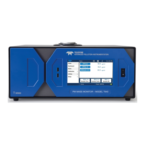
T640
Teledyne T640 Manuals
Manuals and User Guides for Teledyne T640. We have
3
Teledyne T640 manuals available for free PDF download: User Manual, Standard Operating Procedure
Teledyne T640 User Manual (88 pages)
PM Mass Monitor
Brand:
Teledyne
| Category:
Monitor
| Size: 9 MB
Table of Contents
Warranty
6
About this Manual
7
Table of Contents
8
List of Figures
9
1 Introduction, Specifications, Approvals, and Compliance
12
Specifications
12
Table 1-1. Specifications
12
EPA Designation
13
Safety
13
Emc
14
2 Installation and Hardware Setup
14
Unpacking
14
List of Standard Items
15
List of Optional Accessories
15
Figure 2-1. T640 Typical Set of Included Hardware
16
Figure 2-2. 640X Option Typical Set of Included Hardware
17
Ventilation Clearance
18
Instrument Layout
18
Figure 2-3. Front Panel Layout
18
Front Panel
18
Table 2-1. Ventilation Clearance
18
Figure 2-4. T640 Rear Panel
19
Figure 2-5. T640 with 640X Option Rear Panel
19
Rear Panel
19
Figure 2-6. T640 Internal Layout, with 640X Option Components
20
Internal Layout
20
Height Dimensions
21
Connections and Startup
22
Power Connection
22
Aerosol Sample Conditioner (ASC) Connections and Installation
23
Communications Interface Connections
23
Figure 2-7. Top View of Inlet Nozzle
23
Figure 2-8. Inlet Nozzle Adapter for ASC Connection
24
Figure 2-9. Collar for Lower Flange
24
Figure 2-10. Set Screws for ASC
25
Figure 2-11. Collar and ASC Adapter Support
25
Figure 2-12. Ambient Temperature Probe and ASC Connections (T640 with 640X Option Shown)
26
Figure 2-13. T640 Sample Head (5-LPM) and ASC Assembly
27
Inlet Installation
27
Figure 2-14. 640X Option Inlet and ASC Assembly
28
Figure 2-15. Ambient Temperature Sensor Probe Installed into Radiation Shield
28
Indoor/Outdoor Installation
29
Shelter Installation with Roof Penetration
29
Figure 2-16. T640 Inlet Tube and Slip Coupler Assembly
30
Figure 2-17. 640X Inlet Tube and Slip Coupler Assembly
31
Figure 2-18. T640 Inlet and Sample Line Assembly
31
Figure 2-19. 640X Inlet and Sample Line Assembly
32
Figure 2-20. T640 Rooftop Sample Inlet and Extension Tubing Installation
32
Outdoor Enclosure Installation
33
Figure 2-21. T640 (Left) and 640X (Right) Outdoor Enclosures Assembled
34
Pneumatics
35
Figure 2-22. T640 Pneumatics
35
Figure 2-23. T640 with 640X Option Pneumatics
36
Display and Menu Navigation
37
Figure 2-24. Sample Home Screen with Orientation
37
Startup and Functional Checks
38
Figure 2-25. Concentration Graph and Meter Graph
38
Functional Checks of Operating Parameters
38
Startup
38
Initial Sensor Checks and Adjustments
39
3 Software Setup and Operation
39
Menu System Overview
39
Configuration and Setup
40
Homescreen
40
Dashboard
41
Figure 3-1. Home Configuration Thru Home Page Shortcut
41
Figure 3-2. Dashboard
41
Alerts
42
Utilities>Datalog View
42
Utilities>Alerts Log
42
Figure 3-3. Alerts Log
42
Utilities>Usb Utilities (Downloads and Updates)
43
Figure 3-4. USB Utility Pages
43
Downloading das (Data Acquisition System) Data
44
Figure 3-5: das Download Page
44
Updating Software/Firmware
44
Figure 3-6: Remote Update Page
45
Figure 3-7: Manual Update Page (and Other Utilities)
45
Figure 3-8: Configuration Transfer
46
Transferring Configuration to Other Instruments
46
Figure 3-10. Datalog Configuration, New Log Page
47
Figure 3-9: Report Generation Page
47
Generating a Report
47
Setup>Data Logging
47
Creating a User-Defined Data Log
48
Figure 3-11. Datalog Configuration, Existing Log
48
Figure 3-12. Creating a New Data Log
48
Configuring Trigger Types
49
Figure 3-13. Datalog Periodic Trigger Configuration
49
Downloading das (Data Acquisition System) Data
50
Figure 3-14. Datalog - Conditional Trigger Configuration
50
Figure 3-15. das Data Utility
50
Figure 3-16. Events Page
51
Setup>Events
51
Creating User-Defined Events
52
Figure 3-17. Event Configuration
52
Editing or Deleting Events
53
Figure 3-18. Existing Event for Viewing or Editing
53
Figure 3-19. Dashboard Configuration
53
Setup>Dashboard
53
Figure 3-20. VARS Configuration Page
54
Setup>Vars (Variables)
54
Figure 3-21. Home Configuration Thru Setup Menu
55
Setup>Homescreen
55
Figure 3-22. Touchscreen Calibration Page
56
Instrument Display Calibration (for Earlier Instruments)
56
Setup>Instrument
56
Table 3-1. Setup>Instrument Menu
56
Figure 3-23. Date and Time Configuration Page
58
Instrument Date/Time Adjustments
58
Setup>Comm (Communications Setup)
59
Table 3-2. T640 MODBUS Register
59
TCP Port1
59
TCP Port2
59
Figure 3-24. Communications Configuration, Network Settings
61
Network Settings
61
Table 3-3. Lan/Ethernet Configuration Properties
61
Operation
62
4 Sensor Checks and Adjustments
62
Ambient Temperature Sensor Check
63
Figure 4-1. Leak-Check/Flow-Audit Adaptor Kit
63
Pressure Sensor Check and Calibration
64
Figure 4-2. Pressure Cal Menu
64
Sample Flow Cal (5-LPM)
65
Figure 4-3. Sample Flow Cal Menu
65
Bypass Flow Cal (11.67-LPM)
66
Figure 4-4. Bypass Flow Cal Menu
66
PMT Adjustment
67
Figure 4-5. PMT Adjustment Menu
67
Leak Check
69
Figure 4-6. Leak Check Menu
69
5 Maintenance and Service
70
Maintenance Schedule
70
Table 5-1. Maintenance Schedule
70
Maintenance Procedures
71
Cleaning the T640 Inlet
71
Figure 5-1. T640 Inlet (Standard)
71
Cleaning the US EPA PM10 Inlet
72
Figure 5-2. 640X Option Disassembly
72
Changing the Disposable Filter Unit (DFU)
73
Figure 5-3. Opening the Front Panel
73
Figure 5-4. Internal DFU
73
Checking Pump Performance
74
Checking the Volume Flow
74
Figure 5-5. External DFU, (with 640X Option Only)
74
Cleaning the Optical Chamber and the RH/T Sensor
75
Figure 5-6. Maintenance: Optics Chamber Windows
78
Figure 5-7. Maintenance: Final Dusting
78
Inspecting the Sampling Line
80
Checking for Leaks
80
Troubleshooting and Service
81
Fault Diagnosis
81
Table 5-2. Alerts and Recommendations
81
Calibration Problems
82
Flow Problems
82
Technical Assistance
83
6 Principles of Operation
83
Sampling System
84
Inlet
84
Aerosol Sample Conditioner (ASC)
84
Optical Particle Sensor
84
Flow Sensor and Pump Control
84
Electronic Block Diagram
85
Figure 6-1. T640 with 640X Option Electronic Block Diagram
85
APPENDIX A - Warranty Repair Questionnaire
86
APPENDIX B - Menu Hierarchy
88
Advertisement
Teledyne T640 User Manual (69 pages)
PM Mass Monitor
Brand:
Teledyne
| Category:
Monitor
| Size: 3 MB
Table of Contents
User Manual
1
Safety Messages
4
Warranty
6
About this Manual
7
Table of Contents
8
List of Figures
9
1 Introduction, Specifications, Approvals, and Compliance
12
Specifications
12
Table 1-1. Specifications
12
EPA Designation
13
Safety
14
Emc
14
2 Installation and Hardware Setup
14
Unpacking
14
Ventilation Clearance
15
Table 2-1. Ventilation Clearance
15
Instrument Layout
16
Front Panel
16
Figure 2-1. Front Panel Layout
16
Rear Panel
17
Figure 2-2. T640 Rear Panel
17
Figure 2-3. T640 with 640X Option Rear Panel
17
Internal Layout
18
Figure 2-4. T640 Internal Layout
18
Connections and Startup
19
Aerosol Sample Conditioner (ASC) Connections and Installation
20
Figure 2-5. ASC Setup: Inlet Nozzle
20
Figure 2-6. ASC Setup: Aluminum Adapter
20
Figure 2-7. Water Collector Attached to Inlet
21
Figure 2-8. T640 Inlet (Standard) and ASC Assembly
21
Figure 2-9. 640X Option Inlet and ASC Assembly
22
Temperature Probe Connection
23
Figure 2-10. Ambient Temperature Probe and ASC Connections (T640 with 640X Option Shown)
23
Figure 2-11. Ambient Temperature Probe Installed in Solar Shield
23
Power Connection
24
Communications Interface Connections
24
Indoor/Outdoor Installation
25
Shelter Installation with Roof Penetration
25
Outdoor Enclosure Installation
26
Pneumatics
27
Figure 2-12. T640 Pneumatics
27
Figure 2-13. T640 with 640X Option Pneumatics
28
Display and Menu Navigation
29
Figure 2-14. Sample Home Screen with Orientation
29
Startup and Functional Checks
30
Startup
30
Figure 2-15. Concentration Graph and Meter Graph
30
Functional Checks of Operating Parameters
30
Initial Sensor Checks and Adjustments
31
3 Software Setup and Operation
31
Configuration and Setup
31
Homescreen
31
Dashboard
32
Figure 3-1. Home Configuration Thru Home Page Shortcut
32
Figure 3-2. Dashboard
32
Alerts
33
Utilities>Datalog View
33
Utilities>Alerts Log
33
Figure 3-3. Alerts Log
33
Utilities>Usb Utilities
34
Setup>Data Logging
34
Figure 3-4. USB Utility Page
34
Figure 3-5. Datalog Configuration, New Log Page
34
Creating a User-Defined Data Log
35
Figure 3-6. Datalog Configuration, Existing Log
35
Figure 3-7. Creating a New Data Log
35
Configuring Trigger Types
36
Figure 3-8. Datalog Periodic Trigger Configuration
36
Downloading das (Data Acquisition System) Data
37
Figure 3-10. das Data Utility
37
Figure 3-9. Datalog - Conditional Trigger Configuration
37
Figure 3-11. das Data Download
38
Figure 3-12. Events Page
38
Setup>Events
38
Creating User-Defined Events
39
Figure 3-13. Event Configuration
39
Editing or Deleting Events
40
Figure 3-14. Existing Event for Viewing or Editing
40
Figure 3-15. Dashboard Configuration
40
Setup>Dashboard
40
Figure 3-16. VARS Configuration Page
41
Setup>Homescreen
41
Setup>Vars (Variables)
41
Figure 3-17. Home Configuration Thru Setup Menu
42
Instrument Display Calibration
42
Setup>Instrument
42
Figure 3-18. Touchscreen Calibration Page
43
Communications Setup
44
Figure 3-19. Date and Time Configuration Page
44
Instrument Date/Time Adjustments
44
Table 3-1. T640 MODBUS Register
45
Firmware Updates
47
Figure 3-20. Communications Configuration, Network Settings
47
Table 3-2. Lan/Ethernet Configuration Properties
47
Operation
49
4 Adjustments
49
Calibration Checks and Adjustments
50
Pressure Cal
51
Sample Flow Cal (5-LPM)
52
Bypass Flow Cal (11.67-LPM)
53
PMT Adjustment
54
5 Maintenance and Service
55
Maintenance Schedule
55
Table 5-1. Maintenance Schedule
55
Maintenance Procedures
56
Cleaning the T640 Inlet
56
Figure 5-1. T640 Inlet (Standard)
56
Cleaning the US EPA PM10 Inlet
57
Figure 5-2. 640X Option Disassembly
57
Changing the Disposable Filter Unit (DFU)
58
Figure 5-3. Opening the Front Panel
58
Figure 5-4. Internal DFU
58
Checking Pump Performance
59
Checking the Volume Flow
59
Figure 5-5. External DFU, (with 640X Option Only)
59
Cleaning the Optical Chamber and the RH/T Sensor
60
Figure 5-6. Maintenance: Optical Chamber and RH/T Sensor Access
60
Figure 5-7. Maintenance: Location of Optics Chamber and RH/T Sensor
60
Figure 5-8. Maintenance: Optical Chamber Disassembly
61
Figure 5-9. Maintenance: Optics Chamber Windows
61
Inspecting the Sampling Line
62
Checking for Leaks
62
Figure 5-10. Maintenance: Final Dusting
62
Troubleshooting and Service
63
Fault Diagnosis
63
Table 5-2. Alerts and Recommendations
63
Flow Problems
64
Calibration Problems
64
Technical Assistance
64
6 Principles of Operation
65
Sampling System
65
Inlet
65
Aerosolssample Conditioner (ASC)
66
Optical Particle Sensor
66
Flow Sensor and Pump Control
66
Electronic Block Diagram
67
Figure 6-1.T640 with 640X Option Electronic Block Diagram
67
Teledyne T640 Standard Operating Procedure (26 pages)
PM2.5 PARTICULATE MONITOR
Brand:
Teledyne
| Category:
Laboratory Equipment
| Size: 0 MB
Table of Contents
Table of Contents
3
1 Purpose
5
2 Scope and Applicability
5
3 Summary of the Collection Method
5
Principles of Operation
6
4 Definitions and Conversion Factors
6
Table 4-1 Terms and Definitions
7
5 Health and Safety Precautions
8
6 Interferences
8
7 Personnel Qualifications
8
8 Equipment and Supplies
9
Installation Equipment and Supplies
9
Routine Equipment and Supplies
9
9 Installation, Startup and Removal Instructions
9
Installation
9
Site Setup
10
10 Verification/Calibration
10
Instrument Verification
10
Leak Test
11
Pressure Verification
11
Ambient Temperature Verification
12
Flow Verification
12
Figure 1 Pressure Verification Screen
12
PMT Verification
13
Figure 2 Sample Flow Verification
13
Instrument Calibration/Adjustment
14
Figure 3 PMT Adjustment Screen
14
Figure 4 Pressure Calibration Screen
15
Flow Calibration
15
Pressure Sensor Calibration
15
Figure 5 Flow Calibration Screen
16
PMT Adjustment
16
11 Maintenance Procedures
17
Figure 6 PMT Adjustment Screen
17
Cleaning the T640 TSP Inlet
18
Table 11-1 Maintenance Schedule
18
Changing the Disposable Filter Unit (DFU)
19
Figure 7 TSP Inlet
19
Figure 8 Opening the Front Panel
20
Figure 9 Internal DFU
20
Checking Pump Performance
21
Checking the Flow
21
Cleaning the Optical Chamber and the RH/T Sensor
21
Figure 10 ASC Support Removal
21
Figure 11 Location of Optics Chamber and RH/T Sensor
22
Figure 12 Optical Chamber Disassembly
23
Figure 13 Optics Chamber Windows
23
Inspecting the Sample Tubes
24
12 Troubleshooting and Service
24
Fault Diagnosis
24
Figure 14 Final Dusting
24
Table 12-1 Alerts and Recommendations
25
Flow Problems
26
Advertisement
Advertisement
Related Products
Teledyne T3PS11230
Teledyne Tekmar Versa
Teledyne T3CP100-2
Teledyne T3HVD
Teledyne T801
Teledyne T3DSO3034HD
Teledyne T360U
Teledyne Everywhereyoulook T3DSOH1000-ISO
Teledyne T3AWG3K Series
Teledyne 460H NEMA
Teledyne Categories
Measuring Instruments
Analytical Instruments
Test Equipment
Digital Camera
Laboratory Equipment
More Teledyne Manuals
Login
Sign In
OR
Sign in with Facebook
Sign in with Google
Upload manual
Upload from disk
Upload from URL