Table of Contents
Advertisement
Quick Links
See also:
User Manual
Copyright 2016
Teledyne API
User Manual
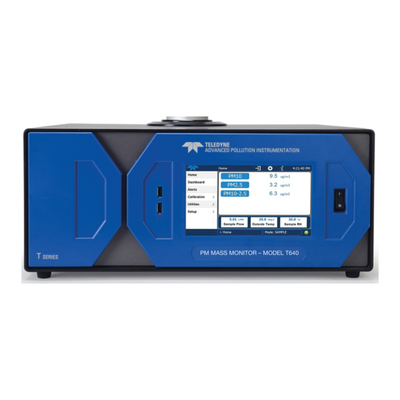
Model T640
PM Mass Monitor
© TELEDYNE API (TAPI)
9970 CARROLL CANYON ROAD
SAN DIEGO, CALIFORNIA 92131-1106
USA
Toll-free Phone:
800-324-5190
Phone:
+1 858-657-9800
Fax:
+1 858-657-9816
Email:
api-sales@teledyne.com
Website:
http://www.teledyne-api.com/
08354A DCN7303
13 July 2016
Advertisement
Table of Contents

Related Manuals for Teledyne T640


Summary of Contents for Teledyne T640
-
Page 1: User Manual
User Manual Model T640 PM Mass Monitor © TELEDYNE API (TAPI) 9970 CARROLL CANYON ROAD SAN DIEGO, CALIFORNIA 92131-1106 Toll-free Phone: 800-324-5190 Phone: +1 858-657-9800 Fax: +1 858-657-9816 Email: api-sales@teledyne.com Website: http://www.teledyne-api.com/ Copyright 2016 08354A DCN7303 Teledyne API 13 July 2016... - Page 3 © 2016 Teledyne API. All rights reserved. TRADEMARKS All trademarks, registered trademarks, brand names or product names appearing in this document are the property of their respective owners and are used herein for identification purposes only. 08354A DCN7303 Teledyne API Model T640 PM Mass Monitor...
-
Page 4: Safety Messages
NEVER use any TAPI analyzer to sample combustible gas(es)! For Technical Assistance regarding the use and maintenance of this instrument or any other Teledyne API product, contact Teledyne API’s Technical Support Department: Telephone: 800-324-5190 Email: sda_techsupport@teledyne.com... - Page 5 Si vous utilisez cet instrument d’une autre manière que celle pour laquelle il a été prévu, l’instrument pourrait se comporter de façon imprévisible et entraîner des conséquences dangereuses. NE JAMAIS utiliser un analyseur de gaz pour échantillonner des gaz combustibles! 08354A DCN7303 Teledyne API Model T640 PM Mass Monitor...
-
Page 6: Warranty
Product Return All units or components returned to Teledyne API should be properly packed for handling and returned freight prepaid to the nearest designated Service Center. After the repair, the equipment will be returned, freight prepaid. -
Page 7: About This Manual
ANUAL This user manual, part number 08354, provides instructions for the setup, installation, and operation of the T640 Real-time Continuous PM Monitor. Support manuals, such as electrostatic discharge (ESD) prevention and various communications, are available on the TAPI website http://www.teledyne-api.com under Product Manuals. -
Page 8: Table Of Contents
Setup>Events ........................36 3.1.8.1. Creating User-defined Events ................37 3.1.8.2. Editing or Deleting Events ..................38 3.1.9. Setup>Dashboard ........................ 38 3.1.10. Setup>VARS (Variables) ....................39 3.1.11. Setup>Homescreen ......................39 3.1.12. Setup>Instrument ....................... 40 Teledyne API T640 PM Mass Monitor 08354A DCN7303... -
Page 9: List Of Figures
Figure 2-8. T640 Inlet (standard) and ASC Assembly ................19 Figure 2-9. 640X Option Inlet and ASC Assembly ..................20 Figure 2-10. Ambient Temperature Probe and ASC Connections (T640 with 640X Option shown) ..21 Figure 2-11. Ambient Temperature Probe Installed in Solar Shield ............21... - Page 10 Figure 5-8. Maintenance: Optical Chamber Disassembly ................59 Figure 5-9. Maintenance: Optics Chamber Windows ................. 59 Figure 5-10. Maintenance: Final Dusting ....................60 Figure 6-1.T640 with 640X Option Electronic Block Diagram ..............65 Teledyne API T640 PM Mass Monitor viii...
- Page 11 IST OF ABLES Table 1-1. Specifications ..........................10 Table 2-1. Ventilation Clearance ......................... 13 Table 3-1. T640 MODBUS Register ......................43 Table 3-2. LAN/Ethernet Configuration Properties ..................45 Table 5-1. Maintenance Schedule ......................53 Table 5-2. Alerts and Recommendations ....................61...
-
Page 12: Introduction, Specifications, Approvals, And Compliance
INTRODUCTION, SPECIFICATIONS, APPROVALS, AND COMPLIANCE The Teledyne API Model T640 with 640X Option is a real-time, continuous particulate matter (PM) mass monitor that uses scattered light spectrometry for measurement. The T640 measures 2.5 PM, and the 640X Option measures 2.5, 10, and coarse PM. -
Page 13: Epa Designation
HxWxD: 45” x 25” x 25” (1143 x 635 x 635 mm) Weight 19 lbs (8.6 kg) w/ T640 ASC + inlet 27 lbs (12.2 kg); w/ 640X Option ASC + inlet 30 lbs (13.6 kg) Optional external shelter 115 lbs (52 kg) -
Page 14: Safety
Verify that there is no apparent external shipping damage. If damage has occurred, please advise the shipper first, then Teledyne API. Included with your instrument is a printed record of the final performance characterization performed on your instrument at the factory. This record, titled... -
Page 15: Ventilation Clearance
MINIMUM REQUIRED CLEARANCE 10 cm / 4 in Back of the instrument 2.5 cm / 1 in Sides of the instrument 2.5 cm / 1 in Above and below the instrument 08354A DCN7303 Teledyne API Model T640 PM Mass Monitor... -
Page 16: Instrument Layout
Figure 2-1 shows the front panel layout, which has the display screen, two USB ports for peripheral device connections: mouse and keyboard as alternatives to the touchscreen interface, or flash drive for uploads/downloads (devices not included). Figure 2-1. Front Panel Layout Teledyne API T640 PM Mass Monitor 08354A DCN7303... -
Page 17: Rear Panel
REAR PANEL The rear panel shows fittings and connectors for the monitor’s functions as well as connectors for communication. Figure 2-2. T640 Rear Panel Figure 2-3. T640 with 640X Option Rear Panel 08354A DCN7303 Teledyne API Model T640 PM Mass Monitor... -
Page 18: Internal Layout
2.2.3. INTERNAL LAYOUT Figure 2-4 shows the main components and assemblies of the monitor. Figure 2-4. T640 Internal Layout Teledyne API T640 PM Mass Monitor 08354A DCN7303... -
Page 19: Connections And Startup
Note To maintain compliance with EMC standards, any cable length must be no greater than 3 meters for all communication connections. 08354A DCN7303 Teledyne API Model T640 PM Mass Monitor... -
Page 20: Aerosol Sample Conditioner (Asc) Connections And Installation
The ASC requires an inlet nozzle and an adapter for installation. The black inlet nozzle to the optical sensor is specific to the instrument (not interchangeable to other T640 instruments). The final assembly differs slightly between the T640 ASC and the 640X Option ASC. -
Page 21: Figure 2-7. Water Collector Attached To Inlet
3. Attach the water collector to the inlet (Figure 2-7). Figure 2-7. Water Collector Attached to Inlet 4. Assemble the inlet and the ASC as depicted in Figure 2-8 for the T640 or in Figure 2-9 for the 640X Option, ensuring the parts fit snugly with no gaps. -
Page 22: Figure 2-9. 640X Option Inlet And Asc Assembly
Figure 2-9. 640X Option Inlet and ASC Assembly 5. Lower the ASC into the support collar, ensuring it fits straight with no gaps. 6. Plug the ASC wiring into the rear panel connector. Teledyne API T640 PM Mass Monitor 08354A DCN7303... -
Page 23: Temperature Probe Connection
TEMPERATURE PROBE CONNECTION 1. Plug the ambient temperature probe connector into its respective rear panel electrical port. Figure 2-10. Ambient Temperature Probe and ASC Connections (T640 with 640X Option shown) 2. Route probe outside and insert into solar shield, ensuring solar shield maintains vertical orientation. -
Page 24: Power Connection
IP address. See Section 3.1.13. For firmware updates and data downloads, use a flash drive inserted into the front panel USB port. See Sections 3.2 and 3.1.7.3. Teledyne API T640 PM Mass Monitor 08354A DCN7303... -
Page 25: Indoor/Outdoor Installation
Make sure the inlet is secure. i.e. that the collar holding it is not sliding. • Proper installation should have the inlet 2-m above the roof. 11. Plug the ASC connector into the proper fitting on the rear panel of the T640. 08354A DCN7303 Teledyne API Model T640 PM Mass Monitor... -
Page 26: Outdoor Enclosure Installation
Make sure the optical sensor nozzle and nozzle to ASC adapter are installed on the optical sensor. 3. Once the T640 is in the enclosure and lined up with the cord grip opening on the top of the enclosure, insert the ASC into the cord grip (from above) and slide it down gently until it inserts into the ASC support of the T640. -
Page 27: Pneumatics
2.7. PNEUMATICS Figure 2-12. T640 Pneumatics 08354A DCN7303 Teledyne API Model T640 PM Mass Monitor... -
Page 28: Figure 2-13. T640 With 640X Option Pneumatics
Figure 2-13. T640 with 640X Option Pneumatics Teledyne API T640 PM Mass Monitor 08354A DCN7303... -
Page 29: Display And Menu Navigation
Figure 2-14. Sample Home Screen with Orientation Figure 2-15 shows that pressing the gas name or its concentration value or a meter below displays a plot of the respective values. (Meters are selectable in HomeScreen, Section 3.1.1). 08354A DCN7303 Teledyne API Model T640 PM Mass Monitor... -
Page 30: Startup And Functional Checks
If not all test functions and values are displayed here, touch the configuration icon to insert additional functions into the Dashboard (Section 3.1.2 has more details). These functions can also be used as diagnostic tools for troubleshooting a performance problem. Teledyne API T640 PM Mass Monitor 08354A DCN7303... -
Page 31: Initial Sensor Checks And Adjustments
To select, go to the Home Configuration page by touching the configuration button (shortcut) and following the onscreen instructions (see Figure 3-1). The Home page can also be configured through the Setup menu (Section 3.1.11). 08354A DCN7303 Teledyne API Model T640 PM Mass Monitor... -
Page 32: Dashboard
The Dashboard page (Figure 3-2) shows an array of user-selected parameters and their values. If there is a graphing icon in the upper right corner of a parameter, pressing that parameter displays a plot. (See Section 3.1.9 for configuration instructions). Figure 3-2. Dashboard Teledyne API T640 PM Mass Monitor 08354A DCN7303... -
Page 33: Alerts
The Alerts Log (Figure 3-3) displays a history of Alerts (Section 3.1.3) that are triggered by factory-defined and user-defined Events (Section 3.1.8), such as warnings and alarms. Figure 3-3. Alerts Log 08354A DCN7303 Teledyne API Model T640 PM Mass Monitor... -
Page 34: Utilities>Usb Utilities
(Figure 3-6). See Sections 3.1.7.1 and 3.1.7.2 for configuration details, and Section 3.1.7.3 for transferring captured instrument data to a flash drive. Figure 3-5. Datalog Configuration, New Log Page Teledyne API T640 PM Mass Monitor 08354A DCN7303... -
Page 35: Creating A User-Defined Data Log
Figure 3-6. Datalog Configuration, Existing Log 3.1.7.1. CREATING A USER-DEFINED DATA LOG Figure 3-7. Creating a New Data Log 08354A DCN7303 Teledyne API Model T640 PM Mass Monitor... -
Page 36: Configuring Trigger Types
The Periodic trigger is a timer-based trigger that is used to log data at a specific time interval. Periodic Trigger requires an interval that is set to number of minutes and a start time that is set to date and time. Figure 3-8. Datalog Periodic Trigger Configuration Teledyne API T640 PM Mass Monitor 08354A DCN7303... -
Page 37: Downloading Das (Data Acquisition System) Data
2. Insert a flash drive into a front panel USB port and wait for the Status field to indicate that the drive has been detected and available buttons are enabled (Figure 3-11). 08354A DCN7303 Teledyne API Model T640 PM Mass Monitor... -
Page 38: Setup>Events
(Section 3.1.8.1) and editing them (Section 3.1.8.2). To view a list of Warnings and Event tags, press the Add button, and highlight a tag to view its description. Figure 3-12. Events Page Teledyne API T640 PM Mass Monitor 08354A DCN7303... -
Page 39: Creating User-Defined Events
Latching Event. To see a description of any tag, touch its name in the list that pops up after touching the Trigger Tag field. Figure 3-13. Event Configuration 08354A DCN7303 Teledyne API Model T640 PM Mass Monitor... -
Page 40: Editing Or Deleting Events
To add a parameter for display in the Dashboard, make a selection from the “Available Tags” column and press the right-pointing button • To remove a parameter from the Dashboard, select a tag from the ”Dashboard” column and press the left-pointing button Teledyne API T640 PM Mass Monitor 08354A DCN7303... -
Page 41: Setup>Vars (Variables)
Home>Setup>Homescreen menu (Figure 3-17. Home Configuration thru Setup Menu) and follow the onscreen instructions. The Home Configuration page can also be accessed by shortcut ( ) in Home (see Section 3.1.1). 08354A DCN7303 Teledyne API Model T640 PM Mass Monitor... -
Page 42: Setup>Instrument
The Setup>Instrument menu shows product and system information and provides access to instrument settings. 3.1.12.1. INSTRUMENT DISPLAY CALIBRATION Although unlikely, if ever the touchscreen appears unresponsive or responds incorrectly, the screen can be calibrated via the Setup>Instrument>Display Settings menu. Teledyne API T640 PM Mass Monitor 08354A DCN7303... -
Page 43: Figure 3-18. Touchscreen Calibration Page
8. If you press the CANCEL button, the calibration won’t be altered. Otherwise, press the ACCEPT button. If any difficulties persist, contact TAPI Technical Support: sda_techsupport@teledyne.com / 800-324-5190 08354A DCN7303 Teledyne API Model T640 PM Mass Monitor... -
Page 44: Instrument Date/Time Adjustments
Setup>COMM menu remains on display until one of the submenus is selected). The T640 supports MODBUS TCP on port 502, or a user-specified port. The TCP Port menu can be used to edit the MODBUS TCP port number. -
Page 45: Table 3-1. T640 Modbus Register
PM10-2.5 12Hr rolling concentration average PM10 24Hr rolling concentration average PM2.5 24Hr rolling concentration average PM10-2.5 24Hr rolling concentration average LED Temperature Ambient Pressure Humidity Sensor Reading Box Temperature Ambient Temperature Probe Reading 08354A DCN7303 Teledyne API Model T640 PM Mass Monitor... - Page 46 5-LPM Flowmeter Calibration Slope 640x Bypass Flowmeter Calibration Slope Pressure Sensor Calibration Slope Setpoint for the sample RH Flow Setpoint for the optical sensor Setpoint for the 640x Option bypass flow RH sensor slope Teledyne API T640 PM Mass Monitor 08354A DCN7303...
-
Page 47: Firmware Updates
/ 800-324-5190. 1. Follow Technical Support’s instructions for copying the firmware files to a flash drive. 2. On the instrument’s front panel Home menu, press USB Utilities to open the utility page. 08354A DCN7303 Teledyne API Model T640 PM Mass Monitor... - Page 48 Install button will be enabled; if the firmware version on the flash drive is the same as or older than the current firmware of the instrument, the Install button will not be enabled. 5. Press the Install button to copy the updated firmware to the instrument. Teledyne API T640 PM Mass Monitor 08354A DCN7303...
-
Page 49: Operation
The following equipment, supplies, and expendables are required for sensor checks and adjustments: • for pressure and flow: auditing device (NIST-traceable pressure standard and flow standard) • for PMT Adjustment: SpanDust™ 08354A DCN7303 Teledyne API Model T640 PM Mass Monitor... -
Page 50: Calibration Checks And Adjustments
For the Pressure Cal and the two Flow Cal menus, note that the “Measured” parameter provides the value measured by the instrument, and the “Actual” parameter is the value that is to be input from the reading measured by the external auditing device. Teledyne API T640 PM Mass Monitor 08354A DCN7303... -
Page 51: Pressure Cal
PRESSURE CAL IMPORTANT: Perform this check/calibration prior to any flow calibration. The pressure measurement of the T640 is for the ambient pressure that the instrument is operated in. No direct pneumatic connection to the instrument needs to be made to perform this check/calibration. -
Page 52: Sample Flow Cal (5-Lpm)
“Calibrate” button on this screen. The Measured Flow value should change to closely match the Actual Flow within a few seconds. 8. For the T640 with the 640X Option, leave the Bypass Tube disconnected and proceed to the bypass flow calibration procedure in Section 4.1.3. -
Page 53: Bypass Flow Cal (11.67-Lpm)
Sample Flow Cal procedure above. Wait at least one minute for the flow to re-stabilize. 2. With the T640 running, go to the Calibration>Bypass Flow Cal menu. 3. Compare the “Measured Flow” in this screen to the Flow Standard. -
Page 54: Pmt Adjustment
1. Navigate to the PMT Adjust screen. 2. Remove the T640 sample inlet or the 640X Option sample inlet and press the Start button on this screen to suspend normal data acquisition and start this adjustment process. -
Page 55: Maintenance And Service
Check volume flow. quarterly 5.2.5 Use NIST-traceable flow transfer standard device: 5.0 LPM ± 0.15 LPM (for T640) and 11.67 LPM ± 0.5 LPM (for 640X opt) (Standard Ambient Temperature and Pressure). Check for leaks quarterly or as needed (Pump PWM 5.2.8... -
Page 56: Maintenance Procedures
10. Reconnect sampling line. 11. Power up the pump from the Setup>Vars>Pump Control menu. This procedure should be repeated per the schedule in Table 5-1. Teledyne API T640 PM Mass Monitor 08354A DCN7303... -
Page 57: Cleaning The Us Epa Pm10 Inlet
7. Reassemble the unit in accordance with the previously scribed match marks. Take particular care to ensure that all O-ring seals are properly sealed and that all screws are uniformly tightened. 8. Power up the pump from the Setup>Vars>Pump Control menu. 08354A DCN7303 Teledyne API Model T640 PM Mass Monitor... -
Page 58: Changing The Disposable Filter Unit (Dfu)
Figure 5-3. Opening the Front Panel 3. Noting its orientation, remove the old DFU by detaching from the pneumatic quick-connect fittings, and replace with a new DFU matching the orientation. Figure 5-4. Internal DFU Teledyne API T640 PM Mass Monitor 08354A DCN7303... -
Page 59: Checking Pump Performance
5.2.4. CHECKING PUMP PERFORMANCE There is one internal pump in the T640. In addition, the 640X Option has a separate external pump. The pump(s) and the valve (640X Option only) must maintain proper flow for measurement accuracy. Check their performance levels in the Dashboard (If these parameters are not found in the Dashboard, configure the Dashboard to add them;... -
Page 60: Cleaning The Optical Chamber And The Rh/T Sensor
2. Locate the optical cell, the cup at bottom of optics chamber and its tubing, and the Relative Humidity and Temperature (RH/T) sensor. Figure 5-7. Maintenance: Location of Optics Chamber and RH/T Sensor Teledyne API T640 PM Mass Monitor 08354A DCN7303... -
Page 61: Figure 5-8. Maintenance: Optical Chamber Disassembly
RH/T sensor tubing from DFU filter. Figure 5-8. Maintenance: Optical Chamber Disassembly 4. Clean the optics chamber interior surfaces, ensuring to include windows, with a lint-free cloth. Figure 5-9. Maintenance: Optics Chamber Windows 08354A DCN7303 Teledyne API Model T640 PM Mass Monitor... -
Page 62: Inspecting The Sampling Line
5.2.8. CHECKING FOR LEAKS The internal components of the T640 are not meant to be under strict vacuum as what would normally be done in a leak test. So, to avoid damage to internal components, it is recommended that the inlet never be capped (air tight) while the instrument pump is running. -
Page 63: Troubleshooting And Service
Check flow calibration. External pump, or bypass flow control valve may need replacing. Sample Temp Warning Sample Temperature Warning (>60) Check ASC (is it latched ON?) Ensure proper climate and ventilation for instrument. 08354A DCN7303 Teledyne API Model T640 PM Mass Monitor... -
Page 64: Flow Problems
+1 858-657-9816 Email: sda_techsupport@teledyne.com Website: http://www.teledyne-api.com/ Before contacting Teledyne API Technical Support, fill out the problem report form in the Appendix, which is also available online for electronic submission at http://www.teledyne-api.com under Technical Support Forms. Teledyne API T640 PM Mass Monitor... -
Page 65: Principles Of Operation
6.1.1. INLET The inlet for the T640 is designed to allow complete transmission of all particle sizes. The US EPA PM10 inlet used for the 640X Option samples at 16.67-LPM to mechanically size-cut the aerosol intake for sampling particles at 10 microns and under. -
Page 66: Aerosolssample Conditioner (Asc)
The flow stream is measured (main flow at 5 LPM for T640 and bypass at 11.67 for 640X Option), and a feedback loop triggers the pump drive voltage adjustments to maintain a constant flow (5 LPM in the T640, 16.67 LPM in the 640x Option). -
Page 67: Electronic Block Diagram
6.2. ELECTRONIC BLOCK DIAGRAM Figure 6-1.T640 with 640X Option Electronic Block Diagram 08354A DCN7303 Teledyne API Model T640 PM Mass Monitor... - Page 68 PHONE: _______________________________ CONTACT NAME: ___________________________ FAX NO. SITE ADDRESS: MODEL TYPE: ______________ SERIAL NO.: _________________ FIRMWARE REVISION: Are there any failure messages? PLEASE COMPLETE THE FOLLOWING TABLE FOR THE T640: PARAMETER RECORDED VALUE ACCEPTABLE VALUE Sample Flow 5.0LPM ±1% Sample Flow Slope 1.0 ±5%...
- Page 69 What tests have you done in trying to solve the problem? _____________________________________ ___________________________________________________________________________________ ___________________________________________________________________________________ ___________________________________________________________________________________ ___________________________________________________________________________________ Thank you for providing this information. Your assistance enables Teledyne Instruments to respond faster to the problem that you are encountering. OTHER NOTES: ______________________________________________________________________ ___________________________________________________________________________________ ___________________________________________________________________________________...
Need help?
Do you have a question about the T640 and is the answer not in the manual?
Questions and answers