Sign In
Upload
Manuals
Brands
Suzuki Manuals
Motorcycle
2004 DL650K4
Suzuki 2004 DL650K4 Manuals
Manuals and User Guides for Suzuki 2004 DL650K4. We have
1
Suzuki 2004 DL650K4 manual available for free PDF download: Service Manual
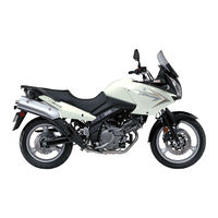
Suzuki 2004 DL650K4 Service Manual (467 pages)
Brand:
Suzuki
| Category:
Motorcycle
| Size: 21.35 MB
Table of Contents
Table of Contents
10
Component Parts
3
Glossary
5
Wire Color
9
Warningka Ution/Note
11
General Precautions
11
Serial Number Location
13
Fuel. Oil and Engine Coolant Recommendation
13
Fuel (for Usa and Canada)
13
Fuel (for Other Countries)
13
Engine Oil (for Usa)
14
Engine Oil (for Other Countries)
14
Brake Fluid
14
Front Fork Oil
14
Engine Coolant
14
Water for Mixing
14
Anti-Freezwengine Coolant
15
Liquid Amount of Watewengine Coolant
15
Break-In Procedures
15
Cylinder Identification
16
Information Labels
17
Specifications
18
Dimensions and Dry Mass
18
Engine
18
Drive Train
18
Chassis
19
Electrical
19
Capacities
19
Country and Area Codes
20
Table of Contents
21
Periodic Maintenance Schedule
22
Periodic Maintenance Chart
22
Lubrication Points
24
Maintenance and Tune-Up Procedures
25
Air Cleaner
25
Spark Plug
26
Valve Clearance
28
Fuel Line
33
Engine Oil and Oil Filter
33
Engine Idle Speed
35
Throttle Cable Play
35
Throttle Valve Synchronization
36
Evaporative Emission Control System (E-33 Only)
36
Pair (Air Supply) System
36
Clutch
37
Cooling System
38
Brake
42
Tire
46
Steering
46
Front Fork
47
Rear Suspension
47
Exhaust Pipe Bolt
47
Chassis Bolt and Nut
48
Compression Pressure Check
50
Compression Test Procedure
50
Oil Pressure Check
51
Table of Contents
52
Engine Components Removable with the Engine in Place
53
Engine Removal and Installation
54
Engine Removal
54
Engine Installation
62
Engine Disassembly
70
Engine Top Side
70
Engine Bottom Side
77
Engine Components Inspection and Servicing
87
Cylinder Head Cover
87
Camshaftkamshaft Journal
88
Cylinder Head
91
Cylinder
101
Piston and Piston Ring
102
Conrod and Crankshaft
104
Crankcase
108
Crankshaft Journal Bearing
112
Crankcase Bearing and Oil Seal
117
Clutch
120
Primary Driven Gear Assembly
121
Gearshift Shaftigearshift Arm
122
Transmission
123
Starter Clutch
130
Generator and Signal Generator
131
Oil Pump
132
Clutch Release
132
Engine Reassembly
133
Engine Bottom Side
133
Engine Top Side
145
Front Cylinde TDC of Compression Stroke
156
Table of Contents
160
Precautions in Servicing
162
Electrical Parts
162
Fuse
163
Ecmnarious Sensors
163
Electrical Circuit Inspection Procedure
165
Using Testers
168
Fi System Technical Features
169
Injection Time (Injection Volume)
169
Compensation of Injection Time (Volume)
170
Injection Stop Control
170
Fi System Parts Location
171
Self-Diagnosis Function
174
User Mode
174
Dealer Mode
175
Tps Adjustment
176
Fail-Safe Function
177
Fi System Troubleshooting
178
CUSTOMER COMPLAINT ANAL Ysls
178
Self-Diagnostic Procedures
180
Self-Diagnosis Reset Procedure
180
Malfunction Code and Defective Condition
181
C12" Ckp Sensor Circuit Malfunction
183
C13" Iap Sensor Circuit Malfunction
185
C14" Tp Sensor Circuit Malfunction
188
C15" Ect Sensor Circuit Malfunction
191
C21" Iat Sensor Circuit Malfunction
193
C23" to Sensor Circuit Malfunction
195
C24" or "C25" IGNITION SYSTEM MALFUNCTION
196
C28" Stv Actuator Circuit Malfunction
197
C29" Stp Sensor Circuit Malfunction
198
C31" Gear Position (Gp) Switch Circuit Malfunction
201
C32" or "C33" FUEL INJECTOR CIRCUIT MALFUNCTION
202
C41" Fp Relay Circuit Malfunction
204
C42" Ig Switch Circuit Malfunction
204
C49" Pair Control Solenoid Valve Circuit Malfunction
205
C44" H02 Sensor (H02S) Circuit Malfunction (E.02. 19)
207
Table of Contents
245
Engine Coolant
247
Cooling Circuit
248
Cooling Circuit Inspection
248
Removal
249
Inspection and Cleaning
251
Installation
251
Radiator Cap
252
Inspection
252
Water Hose
252
Cooling Fan
253
Inspection
253
Removal
253
Installation
253
Cooling Fan Thermo-Switch
254
Inspection
254
Installation
254
Ect Sensor
255
Removal
255
Inspection
255
Installation
256
Thermostat Case Assembly
257
Removal
257
Inspection
257
Installation
258
Water Pump
259
Removal and Disassembly
259
Inspection
261
Reassembly and Installation
262
Lubrication System
265
Oil Pressure
265
Oil Filter
265
Oil Pressure Regulator
265
Oil Strainer
265
Oil Jet
265
Oil Pump
265
Oil Pressure Switch
265
Oil Cooler
266
Removal
266
Inspection and Cleaning
266
Installation
267
Engine Lubrication Flow Chart
268
Engine Lubrication Circuit
269
Table of Contents
271
Construction
272
Removal
275
Installation
279
Front Wheel
280
Removal
281
Inspection and Disassembly
281
Reassembly and Remounting
283
Front Fork
287
Construction
287
Removal and Disassembly
288
Reassembly and Remounting
292
Suspension Setting
296
Steering and Handlebar
297
Construction
297
Removal
298
Inspection and Disassembly
301
Reassembly and Remounting
302
Steering Tension Adjustment
305
Rear Wheel
306
Construction
306
Removal
307
Inspection and Disassembly
308
Reassembly and Remounting
311
Rear Shock Absorber
315
Removal
316
Inspection
317
Rear Shock Absorber Disposal
317
Remounting
318
Suspension Setting
319
Rear Swingarm
320
Removal
321
Inspection and Disassembly
322
Reassembly
325
Final Inspection and Adjustment
328
Front Brake
329
Brake Pad Replacement
330
Brake Fluid Replacement
331
Caliper Removal and Disassembly
332
Caliper Inspection
333
Caliper Reassembly and Remounting
334
Brake Disc Inspection
336
Master Cylinder Removal and Disassembly
336
Master Cylinder Inspection
337
Master Cylinder Reassembly and Remounting
338
Rear Brake
339
Brake Pad Replacement
340
Brake Fluid Replacement
342
Caliper Removal and Disassembly
342
Caliper Inspection
344
Brake Disc Inspection
345
Caliper Reassembly and Remounting
345
Master Cylinder Removal and Disassembly
346
Master Cylinder Inspection
348
Master Cylinder Reassembly and Remounting
348
Inspection
350
Valve Installation
351
Tire Installation
352
Drive Chain
354
Drive Chain Cutting
354
Drive Chain Connecting
355
Table of Contents
358
Cautions in Servicing
359
Connector
359
Fuse
359
Semi-Conductor Equipped Part
360
Battery
360
Connecting the Battery
360
Wiring Procedure 8
360
Location of Electrical Components
362
Charging System
364
Trouble Shooting
364
Inspection
366
System
369
Trouble Shooting
369
Starter Motor Removal and Disassembly
371
Starter Motor Inspection
372
Starter Motor Reassembly
373
Starter Relay Inspection
376
Inspection
377
Ignition System
380
Troubleshooting
380
Inspection
382
Combination Meter
386
Removal and Disassembly
386
Inspection
387
Indicators
389
Lamps
393
Relays
394
Turn Signauside-Stand Relay
394
Starter Relay
394
Fuel Pump Relay
394
Switches
395
Inspection
396
Battery
397
Specifications
397
Initial Charging
397
Servicing
399
Recharging Operation
399
Table of Contents
400
Troubleshooting
401
Malfunction Code and Defective Condition
401
Engine
403
Radiator (Cooling System)
409
Chassis
410
Brakes
411
Battery
414
Speed Sensor Lead Wire Routing
419
Throttle Cable Routing
420
Clutch Cable Routing
421
Throttle Body Installationihose Routing
422
Cooling System Hose Routing
423
Front Brake Hose Routing
425
Fuel Tank Drain Hose Routing
427
Fuel Tank Installation
428
Pair (Air Supply) System Hose Routing
429
Seat Lock Cable Routing
430
Absorber Hose Routing
431
Battery Cushion Installation
431
Side-Stand Set-Up
432
Brake Pedaufootrest Set-Up
432
Engine Cap Installation
433
Footrest Set-Up
434
Handlebar Balancer Installation
434
Special Tools
435
Tightening Torque
439
Fi System Parts
440
Chassis
441
Tightening Torque Chart
442
Service Data
443
Emission Control Systems
456
Fuel Injection System
456
Crankcase Emission Control System
457
Exhaust Emission Control System (Pair System)
458
Noise Emission Control System
459
EVAPORATIVE EMISSION CONTROL SYSTEM (Only for E-33)
459
Hoses
460
Pair Control Solenoid Valve
461
Pair (Air Supply) System Hose Routing
462
Heated Oxygen Sensor (H02S) Wire Routing (E-02,19)
462
(Only for E-33)
464
Hoses
464
Evap Canister
465
Advertisement
Advertisement
Related Products
Suzuki 2004 VL800
Suzuki 2004 GSX-R600
Suzuki 2004 GS500
Suzuki 2004 GS500F
Suzuki 2004 GS500K4
Suzuki 2004 GS500FK4
Suzuki 2005 GSF1200S
Suzuki 2008 VL800C
Suzuki 2008 DL650/AK8
Suzuki 2006 gsxr 600
Suzuki Categories
Motorcycle
Automobile
Motorcycle Accessories
Offroad Vehicle
Musical Instrument
More Suzuki Manuals
Login
Sign In
OR
Sign in with Facebook
Sign in with Google
Upload manual
Upload from disk
Upload from URL