Sign In
Upload
Manuals
Brands
Omron Manuals
Machine Vision Systems
SYSMAC FHV7-C Series
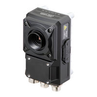
User Manuals: Omron SYSMAC FHV7-C Series Vision Camera
Manuals and User Guides for Omron SYSMAC FHV7-C Series Vision Camera. We have
2
Omron SYSMAC FHV7-C Series Vision Camera manuals available for free PDF download: User Manual, Operation Manual
Omron SYSMAC FHV7-C Series User Manual (647 pages)
for Communication Settings
Brand:
Omron
| Category:
Machine Vision Systems
| Size: 14 MB
Table of Contents
Fh-3£££/Fh
3
Intended Audience
3
Applicable Products
3
Relevant Manuals
4
Manual Structure
6
Page Structure
6
Special Information
7
Conventions Used in this Manual
7
Table of Contents
9
Z342-E1
12
Terms and Conditions Agreement
13
Safety Precautions
15
Precautions for Safe Use
16
Precautions for Correct Use
17
Regulations and Standards
18
Related Manuals
19
Revision History
21
Sections in this Manual
23
Overview
25
Introduction
26
Confirming the System Configuration
27
System Configuration
27
Communicating with an External Device
28
Basic Control Operations of the Sensor Controller
28
Communications between the Sensor Controller and an External Device
29
Control Methods for the Sensor Controller
31
Communication Protocols for Communicating with the Sensor Controller
33
Saving Sensor Controller Data to an External Device
35
Control Methods Using an External Device
37
Control with Control Signals and Status Signals
37
Command/Response Method
40
Data Output after Measurements
41
Setting Procedures for Communications
52
Communications Setup Procedures
52
Communications Protocols and Communications Modules
53
Differences in Specifications Based on the Communications Protocol
55
Differences in Specifications Based on the Communications Pro- Tocol
55
List of Supported Signals by Communications Protocol
55
Restrictions When Using Different Communication Protocols Simultaneously
57
Restrictions When Using Different Communication Protocols Simulta- Neously
57
Restrictions in Communication Protocols by Operation Mode
57
Models Being Compatible with Communication Protocol
58
Ethercat Connections
66
Introduction to Ethercat
66
Structure of CAN Application Protocol over Ethercat (Coe)
69
Ethercat Slave Information Files (ESI Files)
70
Transitions of Communications States
71
Process Data Objects (Pdos)
72
Service Data Objects (Sdos)
75
Communications between Master and Slaves for Ethercat
76
Communication Method of FH Sensor Controller Connected by Ethercat
77
Communications Settings
82
Communications Module Settings (Startup Settings)
84
Communication Specifications Settings
85
Output Data Settings (Processing Item Registration)
90
Setting Output Data (Numerical Values/Character Strings)
93
Ethercat Network Configuration Settings
100
Communication Test
101
I/O Ports by Area (PDO Mapping) and Memory Allocation
102
I/O Signals
108
Measurement Results for Which Output Is Possible (Fieldbus Data Output)
112
Command List
114
Measurement Trigger Input
117
Command Response Processing
118
Data Output
120
Timing Chart
123
Ethercat Troubleshooting
127
Sysmac Error Status
129
Sysmac Device Features
147
Object Dictionary
150
Communicating by PLC Link
189
Communications Processing Flow
189
Communications Settings
191
Communications Module Settings (Startup Settings)
192
Communication Specifications Settings
194
Output Data Settings (Processing Item Registration)
215
Setting Output Data (Numerical Values and Character Strings)
220
Testing Communications
227
Memory Allocation
231
I/O Signals
235
Output Items
238
Command List
239
Command Response Processing
243
Data Output
246
Timing Chart
248
PLC Link Troubleshooting
251
Communicating by Ethernet/Ip
254
Introduction to Ethernet/Ip
254
Data Exchange with Ethernet/Ip
255
Ethernet/Ip Communications
258
Communications Processing Flow
259
Communications Settings
261
Communications Module Settings (Startup Settings)
262
Communication Specifications Settings
263
Setting Tag Data Link
270
Output Data Settings (Processing Item Registration)
275
Setting Output Data (Numerical Values and Character Strings)
280
Testing Communications
287
Memory Allocation
289
I/O Signals
299
Output Items
303
Command List
304
Command Response Processing
308
Data Output
312
Timing Chart
314
Communicating with the Sensor Controller Using Ethernet/Ip Message Communications
317
Communicating with the Sensor Controller Using Ethernet/Ip Mes- Sage Communications
317
Example for Command Settings
320
Ethernet/Ip Troubleshooting
321
Communicating by PROFINET
324
Overview of PROFINET
324
PROFINET Communications
327
Communications Processing Flow
328
Communications Settings
330
Communications Module Settings (Startup Settings)
331
Communication Specifications Settings
332
IO Data Communication Settings
338
Output Data Settings (Processing Item Registration)
340
Setting Output Data (Numerical Values and Character Strings)
344
Testing Communications
351
Memory Allocation
354
I/O Signals
360
Output Items
364
Command List
365
Command Response Processing
368
Data Output
371
Timing Chart
373
PROFINET Troubleshooting
376
Non-Procedure Communications
378
Communications Processing Flow
378
Communications Setup Procedures
379
Communications Module Settings (Startup Settings)
379
Communications Specifications Settings
381
Output Data Settings (Processing Item Registration)
386
Output Data Settings (Numerical Values/Character Strings)
392
Testing Communications
400
Output Items
403
Command Formats
405
Command List
407
Output Format
411
Non-Procedure Communications Troubleshooting
413
Parallel Communications
416
Communications Processing Flow
416
Communications Setup Procedures
418
Communications Module Settings (Startup Settings)
419
Communications Specifications Settings
425
Output Data Settings (Processing Item Registration)
428
Output Data Settings (Numerical Value/Judgment)
434
Testing Communications
440
I/O Signals
442
Output Items
453
Command Formats
455
Time Charts
459
Parallel Troubleshooting
472
Appendices
473
A-1 Command Control
474
A-1-1 Parameter Notation Examples for Command Control
474
Parameter Notation Examples for Command Control
474
A-1-2 Details of Commands Used in Ethercat Communications
478
A-1-3 Command List
479
Command List
479
A-1-4 Command Details for PLC Link, Ethernet/Ip, Ethercat, and PROFINET
487
A-1-5 Non-Procedure Command Details
556
Advertisement
Omron SYSMAC FHV7-C Series Operation Manual (176 pages)
Vision System, for Sysmac Studio
Brand:
Omron
| Category:
Industrial Equipment
| Size: 5 MB
Table of Contents
Fh-1£££/Fh
3
Intended Audience
3
Applicable Products
3
Relevant Manuals
4
Manual Structure
6
Page Structure
6
Special Information
7
Table of Contents
9
Terms and Conditions Agreement
13
Warranty, Limitations of Liability
13
Application Considerations
14
Disclaimers
14
Safety Precautions
16
Precautions for Safe Use
17
Precautions for Correct Use
18
Regulations and Standards
19
Related Manuals
20
Terminology
22
Revision History
23
Sections in this Manual
25
Overview
27
Supported Models
28
Project Management
29
Project Data
29
Project Data Handling in Different System Configurations
30
Basic Operations
35
Basic Design Flow 1
37
Basic Design Flow 2
37
Basic Design Flow 1
39
Basic Design Flow 2
39
Creating a New Project
41
Creating a New Project File from the Project Window
41
Adding FH/FHV Device to a Project
42
Deleting FH/FHV Device from a Project
43
Description of Screen Components
44
Application Window
44
Menu Bar
44
Toolbar
45
Multiview Explorer
45
Edit Pane
47
Toolbox
63
Basic Operations of Scene Data
65
Switching Scenes
65
Managing Scenes
66
Entering Scene Information
66
Searching for a Scene
67
Switching Scene Groups
67
Managing Scene Groups
67
Entering Scene Group Information
68
Basic Operations of Flow Editing
69
Adding a Processing Unit
69
Managing Processing Units
70
Searching for a Processing Unit
72
Function List
73
List of Functions Provided with the FH/FHV Tool
73
Comparison with FH Series Unit Functions
75
Comparison with FHV Series Unit Functions
76
Precautions on Synchronization through an NJ/NX/NY-Series Controller
78
Synchronized Project Data
78
Saving and Loading the Settings Data for the FH/FHV Sensor Controller
79
Transferring Data from the Sysmac Studio
80
Transferring Data to the Sysmac Studio
81
Connecting with a Vision Sensor
85
Connecting with a Vision Sensor
86
Section 3 Connecting with a Vision Sensor
87
3-1 Connecting with a Vision Sensor
87
Adding FH/FHV Series Vision Sensor on the Network to a Project
87
Establishing an Online Connection with a Vision Sensor
88
Establishing an Online Connection from the Sensor Connection Screen
88
Establishing an Online Connection from the Multiview Explorer
89
Synchronizing Project Data and Sensor Setting Data
91
Transferring Project Data to the Sensor
91
Transferring Setting Data in the Sensor to a Project
92
Ending a Connection with a Vision Sensor
94
Ending a Connection in the Sensor Connection Screen
94
Ending a Connection in the Multiview Explorer
94
Logging in to a Registered User's Account
95
Configuring Measurement Settings
97
Section 4 Configuring Measurement Settings
98
Overview of Processing Units
98
Input Image
98
Measurement
98
Compensate Image
98
Support Measurement
99
Branch
99
Output Result
99
Display Result
99
Editing a Processing Unit
101
Parameter Settings
101
Editing an Area
103
Color Extraction
106
Color
107
Binary
107
Detection Point/Reference Point
107
List
108
Image Control Area
108
Designing Exchange with External Devices
111
5-1 Designing Exchange with External Devices
113
Setting Procedure
113
Performing Test Measurement
116
Measuring Camera Images
116
Measuring Logging Images in the Vision Sensor Memory
117
I.e. USB Memory of the Vision Sensor
117
Measuring File Images in the Ramdisk or the External Memory, I.e. USB Memory of the Vision Sensor
117
Checking Measurement Results
118
Checking Detailed Results
118
Changing the Image Display Settings
119
Checking Multiple Measurement Images at the same Time
120
Checking Result Output
121
Saving Measurement Results
122
Saving Settings Data
123
Loading Settings Data
124
Offline Debugging
125
Performing Offline Simulation of Sensor Measurement Operation
125
Performing Offline Simulation of Sensor Measurement Operation
126
Offline Debugging of the Sensor Control Program and Sensor Operation (Only When Using Ethercat Connection)
127
Control Signals Supported with Offline Debugging
127
Offline Debugging Procedure for the Sensor Control Program
128
Other Useful Functions
133
Using the Command Customize Setting Tool
134
Using the Calibration Support Tool
135
Using the File Save Tool
136
Opening the File Save Tool
136
Copying a File
136
Saving a Logging Image as a File
137
Using the User Data Setting Tool
138
Changing the System Environment
139
Help
141
Using the Security Setting Tool
142
Using the Scene Group Saving Destination Setting Tool
143
Using the Image File Save Tool
144
Opening the Image File Save Tool
144
Saving the Image File
144
Saving the Logged Images to Files
145
8-10 Using the Registered Image Manager
147
Using the Update Standard Position Tool
148
Using the Conversion Scene Group Data Tool
149
8-13 Using the Scene Control Macro Tool
150
8-14 Print the Settings
151
Using the Conveyor Panorama Display Tool
152
Using the Conveyor Calibration Wizard Tool
153
8-17 Using the Calibration Plate Print Tool
154
Limitations
155
Synchronization with the NJ/NX/NY-Series Controllers
162
Troubleshooting
163
10-1 Troubleshooting for Ethercat
164
10-2 Sysmac Error Status
165
Appendices
167
A-1 Sysmac Device Features
167
A-1 Sysmac Device Features
168
A-1-1 Sysmac Error Status
168
A-1-2 Saving the Node Address Setting
168
Sysmac Error Status
168
Saving the Node Address Setting
168
A-1-3 Serial Number Display
169
A-1-4 Compliance with ESI Specification (ETG.2000 S (R) V1.0.1)
169
A-1-5 SII Data Check
169
Advertisement
Related Products
Omron FHV7 series
Omron SYSMAC FHV7-S Series
Omron FJ-3000
Omron FJ-3055
Omron FJ-H3055
Omron FZ5-12 series
Omron FJ-300 Series
Omron FJ-300 10 Series
Omron FJ-H305 10 Series
Omron F160-S2
Omron Categories
Blood Pressure Monitor
Controller
Accessories
Switch
Inverter
More Omron Manuals
Login
Sign In
OR
Sign in with Facebook
Sign in with Google
Upload manual
Upload from disk
Upload from URL