Sign In
Upload
Manuals
Brands
Michell Instruments Manuals
Measuring Instruments
XTC601
User Manuals: Michell Instruments XTC601 Gas Analyzer
Manuals and User Guides for Michell Instruments XTC601 Gas Analyzer. We have
2
Michell Instruments XTC601 Gas Analyzer manuals available for free PDF download: User Manual
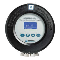
Michell Instruments XTC601 User Manual (85 pages)
Thermal Conductivity Analyzer
Brand:
Michell Instruments
| Category:
Measuring Instruments
| Size: 0 MB
Table of Contents
Table of Contents
4
Safety
7
Electrical Safety
7
Hazardous Area Safety
9
Pressure Safety
10
Temperature Safety
10
Toxic Materials
10
Repair and Maintenance
10
Calibration
10
Safety Conformity
10
Abbreviations
11
1 Introduction
12
Figure 1 XTC601 Thermal Conductivity Analyzer Versions
12
Features
13
Applications
14
O-Ring Selection
14
2 Operation
15
Preparation
15
Powering up the Analyzer
16
Figure 2 Initializing Screen
16
Figure 3 Main Page
16
User Interface
17
Interface Controls
17
Figure 5 XTC601 Application Software
17
Figure 4 User Interface
17
ESC' Button
18
Up/Down Arrow' Buttons
18
ENTER' Button
18
Figure 6 ESC Button
18
Figure 7 Up/Down Arrow Buttons
18
Figure 8 ENTER Button
18
Menu Structure
19
Menu Map
20
Figure 9 Menu Map - Standard XTC601
20
Figure 10 Menu Map - HCG Version
21
Front Pages (no Passcode Required)
22
Main Page
22
Figure 11 Main
22
Chart Page
23
Figure 12 Chart Page
23
Secondary Parameters Page
24
Figure 13 Secondary Parameters Page
24
Target Gas Min/Max Page
25
Alarms Log Pages
25
Figure 14 Target Gas Min/Max Page
25
Figure 15 Alarms Log Page
25
Info Page
26
Figure 16 Info Page
26
User Set-Up Variables (Passcode Required)
27
Figure 17 User Menu (Standard Version)
27
Figure 18 User Menu (HCG Version)
27
Settings Page
28
Figure 19 Settings Page (Standard Version Only)
28
Human Machine Interface (HMI) Page
29
Figure 20 HMI Page
29
Reset Page
30
Alarms Page (HCG Version Only)
30
Figure 21 Reset Page
30
Figure 22 Alarm Page
30
Outputs Page
31
Figure 23 Outputs Page
31
External Compensation Page (Standard Version Only)
32
Figure 24 External Compensation Page
32
Phase Page (HCG Version Only)
33
External Sensor Page
33
Figure 25 Phase Page
33
Figure 26 External Sensor Page
33
Clock Page (Standard Model Only)
34
Figure 27 Clock Page
34
2.7.10 Field Cal Page
35
Figure 28 Field Cal Page
35
2.7.11 Status LED or Light Guide
36
3 Calibration
37
Point Calibration
38
Figure 29 1 Point Calibration Page
38
Point Calibration
39
Figure 30 2 Point Calibration Page
39
Field Calibration Reset
40
Figure 31 Reset Page
40
4 Installation
41
Unpacking
42
System Components
42
Figure 32 XTC601 Showing Major Components
42
Casing
43
Set-Up
43
Figure 33 XTC601 Lid Removal
43
Mechanical Installation
44
Figure 34 XTC601 Gas Connections and Cable Entries
44
Gas Connection Tape
45
Sample Gas Requirements
45
Calibration Gases
45
Electrical Installation
46
Power Supply and Input/Output Signal
46
Power Supply (PL9 - Green)
46
Analog Output
46
Figure 35 Terminal Block Locations
46
Serial Output
47
Analog (4-20 Ma) Outputs and Communications (PL5 - Green)
47
Alarm Relay Contacts (PL1- Black)
47
Analog (4-20 Ma) Inputs and Sensor Excitation Voltage (PL4 - Green)
48
Light Guide
48
Appendix A Technical Specifications
49
Standard XCT601
50
HCG Version
52
Appendix B Dimensional Drawings
55
Figure 36 2 Port Dimensional Drawings
55
Figure 37 4 Port Dimensional Drawings
56
Appendix C Thermal Conductivity Table
58
Appendix D Modbus Register Map (Standard Version)
60
Appendix E Modbus Register Map (HCG Version)
67
Appendix F Hazardous Area Certification
75
Product Standards
75
Global Certifi Cates/Approvals
75
Special Conditions
75
Maintenance and Installation
76
Appendix Geu Declarations
78
EU Declaration of Conformity - GP Version
78
EU Declaration of Conformity - EX Version
79
Appendix H Quality, Recycling, Compliance & Warranty Information
81
Appendix I Analyzer Return Document & Decontamination Declaration
83
Advertisement
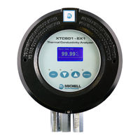
Michell Instruments XTC601 User Manual (80 pages)
Binary Gas Analyzer
Brand:
Michell Instruments
| Category:
Analytical Instruments
| Size: 3 MB
Table of Contents
Table of Contents
4
Safety
7
Electrical Safety
7
Hazardous Area Safety
8
Pressure Safety
9
Temperature Safety
9
Toxic Materials
10
Repair and Maintenance
10
Calibration
10
Safety Conformity
10
Abbreviations
10
1 Introduction
11
Figure 1 XTC601 Binary Gas Analyzer Versions
11
Features
12
Applications
13
O-Ring Selection
13
2 Operation
14
Preparation
14
Powering up the Analyzer
15
Figure 2 Initializing Screen
15
Figure 3 Main Page
15
User Interface
16
Interface Controls
16
Figure 4 User Interface
16
Figure 5 XTC601 Application Software
16
ESC' Button
17
Up/Down Arrow' Buttons
17
ENTER' Button
17
Figure 6 ESC Button
17
Figure 7 Up/Down Arrow Buttons
17
Figure 8 ENTER Button
17
Menu Structure
18
Changing the Passcode
18
Menu Map
19
Figure 9 Menu Map - Standard XTC601
19
Figure 10 Menu Map - HCG Version
20
Front Pages (no Passcode Required)
21
Main Page
21
Figure 11 Main
21
Chart Page
22
Figure 12 Chart Page
22
Secondary Parameters Page
23
Figure 13 Secondary Parameters Page
23
Target Gas Min/Max Page
24
Alarms Log Pages
24
Figure 14 Target Gas Min/Max Page
24
Figure 15 Alarms Log Page
24
Info Page
25
Figure 16 Info Page
25
User Set-Up Variables (Passcode Required)
26
Figure 17 User Menu (Standard Version)
26
Figure 18 User Menu (HCG Version)
26
Settings Page
27
Figure 19 Settings Page (Standard Version Only)
27
Human Machine Interface (HMI) Page
28
Figure 20 HMI Page
28
Figure 21 Date and Time Page
29
Reset Page
30
Figure 22 Reset Page
30
Alarms Page
31
Figure 23 Alarm Page
31
Alarm Page (HCG Version Only)
32
Figure 24 Alarm Page (HCG Version Only)
32
External Compensation Page (Standard Version Only)
33
Figure 25 External Compensation Page
33
Phase Page (HCG Version Only)
34
Figure 26 Phase Page
34
External Sensor Page
35
Figure 27 External Sensor Page
35
Outputs Page
36
Figure 28 Outputs Page
36
Figure 29 NAMUR ERR Page
37
2.7.10 Field Cal Page
38
Figure 30 Field Cal Page
38
2.7.11 Status LED or Light Guide
39
3 Calibration
40
Factory Calibration
40
Field Calibration
40
Before Calibration
40
Calibration Pressure / Flow Rate
41
1-Point Calibration
41
Figure 31 1-Point Calibration Page
41
2-Point Calibration
42
Figure 32 2-Point Calibration Page
42
Field Calibration Reset
43
Figure 33 Reset Page
43
4 Installation
44
Unpacking
44
System Components
45
Figure 34 XTC601 Showing Major Components
45
Set-Up
46
Figure 35 XTC601 Lid Removal
46
Mechanical Installation
47
Gas Connection Tape
47
Figure 36 XTC601 Gas Connections and Cable Entries
47
Sample Gas Requirements
48
Calibration Gases
48
Electrical Installation
49
Power Supply and Input/Output Signal
49
Power Supply
49
Analog Output
49
Figure 37 Terminal Block Locations
49
Serial Output
50
Analog (4-20Ma) Outputs and Communications
50
Alarm Relay Contacts
50
Analog (4-20Ma) Inputs and Sensor Excitation Voltage
51
Light Guide
51
Appendix A Technical Specifications
53
Standard XTC601
53
XTC601 for Monitoring Hydrogen Cooled Generators
55
Appendix B Dimensional Drawings
57
Figure 38 Dimensional Drawings
57
Appendix C Thermal Conductivity Table
59
Appendix D Modbus Register Map (Standard Version)
61
Appendix E Modbus Register Map (HCG Version)
67
Appendix F Hazardous Area Certification
74
Product Standards
74
Global Certificates/Approvals
74
Special Conditions
75
Maintenance and Installation
75
Appendix G Quality, Recycling, Compliance & Warranty Information
77
Appendix H Analyzer Return Document & Decontamination Declaration
79
Advertisement
Related Products
Michell Instruments XTC501
Michell Instruments XTP501
Michell Instruments XZR400 Series
Michell Instruments XZR400A2
Michell Instruments XZR-400-RM
Michell Instruments XZR-400-WM
Michell Instruments XZR-400-TP
Michell Instruments XZR400A3
Michell Instruments XZR250
Michell Instruments XPM601
Michell Instruments Categories
Measuring Instruments
Transmitter
Analytical Instruments
Accessories
Test Equipment
More Michell Instruments Manuals
Login
Sign In
OR
Sign in with Facebook
Sign in with Google
Upload manual
Upload from disk
Upload from URL