Table of Contents
Advertisement
Quick Links
Advertisement
Table of Contents

Related Manuals for Michell Instruments XTC601


Summary of Contents for Michell Instruments XTC601
- Page 1 XTC601 Binary Gas Analyzer User’s Manual 97400 Issue 6.1 November 2020...
- Page 2 Please fill out the form(s) below for each instrument that has been purchased. Use this information when contacting Michell Instruments for service purposes. Product Name Order Code Serial Number Invoice Date Installation Location Tag Number Product Name Order Code Serial Number...
- Page 3 © 2020 Michell Instruments This document is the property of Michell Instruments Ltd and may not be copied or otherwise reproduced, communicated in any way to third parties, nor stored in any Data Processing System without the express written authorization of Michell Instruments Ltd.
-
Page 4: Table Of Contents
XTC601 User’s Manual Contents Safety ..........................vii Electrical Safety ......................vii Hazardous Area Safety ....................viii Pressure Safety ......................ix Temperature Safety ......................ix Toxic Materials ......................ix Repair and Maintenance ....................x Calibration ........................x Safety Conformity ......................x Abbreviations ........................x INTRODUCTION ....................1 Features ...................... - Page 5 4.5.8 Light Guide ....................41 Appendices Appendix A Technical Specifications ................43 Standard XTC601 ................ 43 XTC601 for Monitoring Hydrogen Cooled Generators ..... 45 Appendix B Dimensional Drawings................47 Appendix C Thermal Conductivity Table ...............49 Appendix D Modbus Register Map (standard version) ............51 Appendix E Modbus Register Map (HCG version) ............57...
- Page 6 Figure 33 Reset page....................33 Figure 34 XTC601 Showing Major Components ............35 Figure 35 XTC601 Lid Removal .................36 Figure 36 XTC601 Gas Connections and Cable Entries ..........37 Figure 37 Terminal Block Locations ................39 Figure 38 Dimensional Drawings................47 97400 Issue 6.1, November 2020...
-
Page 7: Safety
XTC601 User’s Manual Safety The manufacturer has designed this equipment to be safe when operated using the procedures detailed in this manual. The user must not use this equipment for any other purpose than that stated. Do not apply values greater than the maximum value stated. -
Page 8: Hazardous Area Safety
Earth stud to plant Earth by a minimum 4mm earthing bonding. Fuse – A replacement fuse can be obtained by contacting Michell Instruments' technical support. Michell order number – XTC601-26149. This product is designed to operate, as a minimum, between a temperature range of -5 to +40°C (+23 to +104°F), in maximum 80% relative humidity for temperatures up to +31°C (+87°F) decreasing... -
Page 9: Pressure Safety
Pressurized gas should only handled by suitably trained personnel. The XTC601 measurement chamber requires pressurized gas to be connected to it. Observe pressurized gas handling regulations. Suitably trained personnel only should carry out tasks that include the use of pressurized gas mediums. -
Page 10: Toxic Materials
Long exposure to, or breathing of the calibration gases, may be dangerous. Repair and Maintenance The instrument must be maintained either by the manufacturer or an accredited service agent. For Michell Instruments’ worldwide offices contact information go to www.michell.com. Calibration The recommended calibration interval for the analyzer is 1 month. -
Page 11: Introduction
The GP2 version is for use with flammable gases in a safe area. The XTC601 is available in single phase configuration for measurement of a variety of binary gases, or in three phase 'HCG' configuration for hydrogen cooled generator applications only. -
Page 12: Features
When required, the casing unscrews to allow for easy access to the sensor, enabling maintenance to be carried out quickly and easily. • The XTC601 is certified to ATEX, IECEX & cQPSus for use in hazardous areas. • 2 x single pole change-over relay alarms for Target Gas concentration, supplied as standard. -
Page 13: Applications
He recovery (Industrial Gas) O-Ring Selection The XTC601 has only one elastomeric seal in the gas path. There are 3 types of O-rings available to offer greater flexibility with material compatibility. The Viton O-ring is fitted as standard. The Ekraz O-ring is available for solvent resistance. For extremely low temperatures there is a closed cell Silicone O-ring. -
Page 14: Operation
XTC601 User’s Manual OPERATION OPERATION The XTC601 is not certified for use with ambient oxygen levels that are enriched (i.e. over 21% O This analyzer has been manufactured within our quality procedures and is configured according to the purchase order. When it is installed and used as per the manufacturer’s guidelines, it will operate within the stated specification. -
Page 15: Powering Up The Analyzer
(122°F) and protect it from any condensation forming in the sensor. There is no power switch on the XTC601 Binary Gas Analyzer. It is turned on automatically once a 24 V DC power source is applied. After the analyzer is powered up, the display will be illuminated. -
Page 16: User Interface
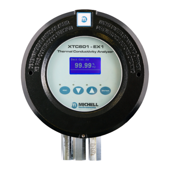
XTC601 User’s Manual OPERATION User Interface 2.3.1 Interface Controls XTC601-EX1 Thermal Conductivity Analyzer Backlit LCD Blue LEDs ENTER Up/Down ENTER Arrow Button Button Buttons Figure 4 User Interface The diagram above illustrates the user interface, which consists of a backlit Liquid Crystal Display and 4 touch-sensitive pads that facilitate user interaction through the glass of the enclosure. -
Page 17: Esc' Button
XTC601 User’s Manual OPERATION 2.3.2 ‘ESC’ Button Figure 6 ESC Button button is used to exit the current menu and to return to the previous menu. From the Main Page, pressing will access the Info Page. 2.3.3 ‘Up/Down Arrow’ Buttons... -
Page 18: Menu Structure
XTC601 User’s Manual OPERATION Menu Structure The XTC601 front pages allow the user to scroll through and view Target Gas concentration, recent trend, internal parameters, minimum & maximum concentration and alarm history. In order to change any settings on the User Menu pages, the user must enter a passcode. -
Page 19: Menu Map
PARAMETERS 2.5.3 SETTINGS 2.7.1 MIN / MAX 2.5.4 DATE/TIME 2.7.2 2.7.2.1 ALARMS LOG 2.5.5 RESET 2.7.3 ALARMS 2.7.4 EXT. COMPENSATION 2.7.6 EXT. SENSOR 2.7.8 OUTPUTS NAMUR 2.7.9 2.7.9.1 FIELD CAL 2.7.10 Figure 9 Menu Map – Standard XTC601 Michell Instruments... -
Page 20: Figure 10 Menu Map - Hcg Version
XTC601 User’s Manual OPERATION INFO PAGE FRONT PAGE ENTER 2.5.1 PASSCODE CHART 2.5.2 MAIN MENU SECONDARY PARAMETERS SETTINGS 2.5.3 2.7.1 MIN / MAX 2.5.4 DATE/TIME 2.7.2 2.7.2.1 ALARMS LOG 2.5.5 RESET 2.7.3 ALARMS 2.7.5 PHASE 2.7.7 EXT. SENSOR 2.7.8 OUTPUTS 2.7.9... -
Page 21: Front Pages (No Passcode Required)
OPERATION Front Pages (No Passcode Required) The EX1 and GP1 versions of the XTC601 have 5 front pages that the user can display without the need for a passcode. NOTE: These are for display of information only and there is no way of adjusting any settings on these pages. -
Page 22: Chart Page
XTC601 User’s Manual OPERATION Status Message Table Message Status LED (Trigger Condition) Out of range Out of range (beyond calibration range, e.g. 0–25%) Low alarm ON Low alarm ON ORANGE1 ON (app s/w only) High alarm ON High alarm ON... -
Page 23: Secondary Parameters Page
XTC601 User’s Manual OPERATION • Chart data is not available via serial comms or in the blind unit as the Application Software is able to perform more sophisticated charting functions. NOTE: This data is not available via the Modbus 2.5.3 Secondary Parameters Page CELL T, °C... -
Page 24: Target Gas Min/Max Page
XTC601 User’s Manual OPERATION 2.5.4 Target Gas Min/Max Page MINIMUM 0.00 %CO2 D12/01 19:29:44 MAXIMUM 0.00 %CO2 D12/01 19:29:44 Figure 14 Target gas min/max page This indicates the minimum and maximum Target Gas values measured, along with date/ time of occurrence. The value is reset manually via the Reset Page in the User Menu. -
Page 25: Info Page
XTC601 User’s Manual OPERATION Info Page 1.01 Firmware Ver Hours Used Last Cal Date 04:01:14 M ModBus Rx Code Figure 16 Info page From the Main Page it is possible to get to the Info Page by pressing the button. -
Page 26: User Set-Up Variables (Passcode Required)
XTC601 User’s Manual OPERATION User Set-Up Variables (Passcode Required) In order to change any settings on the User Menu pages, the user must enter a passcode. There is also a separate passcode for service engineers to allow factory setting changes. -
Page 27: Settings Page
XTC601 User’s Manual OPERATION 2.7.1 Settings Page FIELD CAL ON/OFF EXT COMP ON/OFF ON/OFF LIMIT 0-100% 1/128 MODBUS ID Figure 19 Settings page (Standard version only) The analyzer is microprocessor-based and, as such, has settings and features accessible to the user. -
Page 28: Human Machine Interface (Hmi) Page
XTC601 User’s Manual OPERATION 2.7.2 Human Machine Interface (HMI) Page 0-100% CONTRAST BRIGHTNESS 0-100% TEMPR UNIT C/F/K psia, bara, kpa EXT PRESS UNIT 2-60s CHART INTVAL DATE DD/MM/YY Figure 20 HMI page It is possible to change parameters within the HMI, as in table 6:... -
Page 29: Figure 21 Date And Time Page
XTC601 User’s Manual OPERATION 2.7.2.1 Date and Time Page (scroll down past date in HMI page) HOURS 00-23 00-59 MINS 1-31 1-12 MONTH 00-99 YEAR **:**:** LIVE CLOCK Figure 21 Date and Time Page The real time clock and calendar is used to store date/time information for log data, min/max data and date of calibration. -
Page 30: Reset Page
XTC601 User’s Manual OPERATION 2.7.3 Reset Page MIN/MAX RESET? ALARM LOGS DELETE? DELETE? FIELD CAL Figure 22 Reset page Min/Max and Alarm Logs can be cleared from this menu. See Sections 2.5.4 and 2.5.5 respectively for more information. This menu can also be used to restore the original calibration settings. For more information see Section 3.3. -
Page 31: Alarms Page
XTC601 User’s Manual OPERATION 2.7.4 Alarms Page The analyzer is supplied with two alarm relays; Single Pole Change-Over (SPCO) which are freely assignable within the calibrated range. The alarm relays are rated to 250 V, 5 A maximum. AL1 SETPOINT 0.00... -
Page 32: Alarm Page (Hcg Version Only)
XTC601 User’s Manual OPERATION 2.7.5 Alarm page (HCG version only) ALARM H2/AIR AL1 SETPOINT 0-100 % AL1 CONFIG ON/OFF AL2 SETPOINT 0-100 % AL2 CONFIG ON/OFF Figure 24 Alarm page (HCG version only) This page allows the user to configure alarm trip points for each of the two relay contacts. -
Page 33: External Compensation Page (Standard Version Only)
XTC601 User’s Manual OPERATION 2.7.6 External Compensation Page (standard version only) COMP 20% 0.50-2.00 COMP 40% 0.50-2.00 COMP 60% 0.50-2.00 COMP 80% 0.50-2.00 COMP 100% 0.50-2.00 Figure 25 External Compensation page A 4–20mA sensor may be used to compensate the % Target Gas reading for the effects of process variables such as line pressure, flow, etc. -
Page 34: Phase Page (Hcg Version Only)
XTC601 User’s Manual OPERATION 2.7.7 Phase Page (HCG version only) HMI/MBUS CONTROL H2/AIR PHASE Figure 26 Phase page This page allows for the user to change the currently measured phase. The user can also choose between internal phase control (via the screen) or external control via the 4–20mA input. -
Page 35: External Sensor Page
Figure 27 External sensor page This page sets up the type and range of the 4–20mA external sensor signal that may be connected to the XTC601 for viewing in the Main Page. The range is adjustable Other Other between the MIN and MAX values but is not adjustable for setting (fixed at 0% and 100%). -
Page 36: Outputs Page
XTC601 User’s Manual OPERATION 2.7.9 Outputs Page CH1 TRIM Z 3300 CH1 TRIM S CH2 TRIM Z 3300 CH2 TRIM S CH2 ZERO 0.00 CH2 SPAN 10.00 Figure 28 Outputs page The analyzer has two 4–20mA outputs and 2 concentration alarm relays. The primary 4–20mA is fixed to the calibrated range of the unit, the second is freely selectable within... -
Page 37: Figure 29 Namur Err Page
XTC601 User’s Manual OPERATION 2.7.9.1 NAMUR Output Set-Up NAMUR ERR LOW/HIGH Figure 29 NAMUR ERR Page During initial warm up, or in the event of a sudden change of cell temperature beyond 0.5°C from the set point, the mA output will be driven to an alarm state of either LOW (3.5mA) or HIGH 21.4m according to the user NAMUR ERR output setting. -
Page 38: 2.7.10 Field Cal Page
XTC601 User’s Manual OPERATION 2.7.10 Field Cal Page CAL TYPE 1/2 POINT REF GAS 1 0.00-100.00 ACTUAL 1 0.00-100.00 REF GAS 2 0.00-100.00 ACTUAL 2 0.00-100.00 Adjusted% ~ 0.00-100.00 Figure 30 Field Cal page In the HCG version, the calibration parameters shown in Table 13 will be for the currently selected phase. -
Page 39: 2.7.11 Status Led Or Light Guide
XTC601 User’s Manual OPERATION 2.7.11 Status LED or Light Guide The Status LED or Light Guide options have identical functionality and take their input from the same board. Therefore, only one of them can be selected. For either option the information available is as follows: Power LED •... -
Page 40: Calibration
Zero Point. Field Calibration Like all process analyzers, the XTC601 will require periodic calibration. The frequency entirely depends on the location, application and accuracy requirements of the user. The typical calibration period is expected to be between 1 and 3 months. If the calibration period is in excess of 1 month Michell recommends a Zero and Span calibration. -
Page 41: Calibration Pressure / Flow Rate
XTC601 User’s Manual CALIBRATION Calibration Pressure / Flow Rate General Purpose units: • Sample Inlet Pressure: Constant from 0 to 2 barg (0 to 29 psig) • Sample Flow Rate: Stable from 100 to 500 ml/min (0.25 to 1.0 scfh) Ex or GP units with flame arrestors: •... -
Page 42: 2-Point Calibration
XTC601 User’s Manual CALIBRATION 3 times. Ensure that the Adjusted value is now equal to the REF 1 value ENTER ENTER (±0.01%). Press to de-select. Press to return to the Main Menu. The Adjusted reading will now be the same as that displayed on the Main Page and be equal to the calibration gas. -
Page 43: Field Calibration Reset
XTC601 User’s Manual CALIBRATION ENTER ENTER Down Down Press to highlight REF GAS 2 and use the () and ) buttons to match the value of the concentration of the upper calibration gas. NOTE: This value only needs to be set when... -
Page 44: Installation
Unpacking If sold separately (not part of a sampling system), the XTC601 will be supplied in a custom box which should be retained for future use (such as service return). The box contains a small carton containing 2 lid keys and 1 hex key (for the grub screw). Any cable glands supplied will also be in the smaller carton. -
Page 45: System Components
XTC601 User’s Manual INSTALLATION System Components The XTC601 Binary Gas Analyzer benefits from a modular construction, with the major parts of the analyzer shown below: Figure 34 XTC601 Showing Major Components Instrument case Thermal cut-out fuse Power supply (24 V DC) connector (PL9) -
Page 46: Set-Up
Set-Up • The XTC601 is designed to be panel or wall mounted. There are 2 bolt holes and 2 lugs (1 per corner) see Figure 11 . Dimensional drawings can be found in Appendix B. Mount the analyzer before attempting to remove the lid. -
Page 47: Mechanical Installation
) any PTFE tape used must be unsintered. This is to prevent an explosion due to conventional PTFE tape acting as a potential fuel source. Unsintered PTFE tape is available as an accessory from Michell Instruments (PTFE- TAPE-02). Michell Instruments... -
Page 48: Sample Gas Requirements
INSTALLATION XTC601 User’s Manual 4.4.2 Sample Gas Requirements Samples must have a dew point at least 5°C less than the cell temperature (so as not to condense), be free from oil-mist and with particle size < 3µm. NOTE: There is NO filtration inside the analyzer. -
Page 49: Electrical Installation
4.5.1 Power Supply and Input/Output Signal The XTC601 requires 24 V DC power input at a maximum start-up current of 1.5 A. Warning: DO NOT attempt to loop power this analyzer. All versions will use a braid screened multi-core cable. Ideally, one cable for signals (PL4, PL5) and another cable for power (PL9) / relay contacts (PL1). -
Page 50: Serial Output
INSTALLATION XTC601 User’s Manual 4.5.4 Serial Output The analyzer has Modbus RTU communications over RS485 protocol; please see Application Software CD for more details. • Type: Modbus RTU over RS485 • RS485: 2 wire (plus ground), half duplex • Baud Rate: 9600 •... -
Page 51: Analog (4-20Ma) Inputs And Sensor Excitation Voltage
PIN 3 PIN 2 PIN 1 Exc.V Exc.V The XTC601 features 2 input channels for 4–20mA signal from external instruments such as pressure transmitters or other devices to compensate for pressure or background gas influence. EXT SENS EXT SENS The input configured as... - Page 52 XTC601 User’s Manual APPENDIX A Appendix A Technical Specifications 97400 Issue 6.1, November 2020...
-
Page 53: Appendix A Technical Specifications
XTC601 User’s Manual APPENDIX A Appendix A Technical Specifications Standard XTC601 Performance Measurement Technology Thermal Conductivity sensor Measured Gases (select one) , CH , Ar, He, N or Air Gas Requirements Non-condensing sample with particles <3μm Measurement Range Selectable from 0–1 up to 0–100% 50–100% up to 98–100% Display Resolution 0.1% (0.01% for span ≤... - Page 54 Hazardous Area Classification – See Appendix F * The standard intrinsic error and response time will be as above. Certain gas combinations and/or ranges may have different specifications. Please consult Michell Instruments for specific cases. For example, CO would be < 50 seconds for T90.
-
Page 55: Xtc601 For Monitoring Hydrogen Cooled Generators
XTC601 User’s Manual APPENDIX A XTC601 for Monitoring Hydrogen Cooled Generators Performance Phase 1 – Phase 2 – Phase 3 – Phase in Air in CO in Air 80–100% or Measurement Range 0–100% 0–100% 90–100% Display Resolution 0.01% 0.1% Response Time (T90) <... - Page 56 APPENDIX B XTC601 User’s Manual Appendix B Dimensional Drawings 97400 Issue 6.1, November 2020...
-
Page 57: Appendix B Dimensional Drawings
XTC601 User’s Manual APPENDIX B Appendix B Dimensional Drawings 234 mm 9.21" 9 mm 0.35" TYP 195 mm 7.68" 172 mm 6.77" 11.5 mm 172 mm 0.45" 6.77" 15 mm 0.59" 15 mm 0.59" 12 mm 171 mm 0.47" 6.73"... - Page 58 APPENDIX C XTC601 User’s Manual Appendix C Thermal Conductivity Table 97400 Issue 6.1, November 2020...
-
Page 59: Appendix C Thermal Conductivity Table
XTC601 User’s Manual APPENDIX C Appendix C Thermal Conductivity Table Formula Temperature=50°C (122°F) in mW/(m.K) Commonly Used Gases Hydrogen 196.86 Helium 163.55 Methane 38.01 Oxygen 28.24 27.64 Nitrogen 27.57 Ethane 24.63 Argon 18.79 Carbon-dioxide 18.74 Other gases for reference Ammonia 27.90... - Page 60 APPENDIX D XTC601 User’s Manual Appendix D Modbus Register Map (standard version) 97400 Issue 6.1, November 2020...
-
Page 61: Appendix D Modbus Register Map (Standard Version)
XTC601 User’s Manual APPENDIX D Appendix D Modbus Register Map (standard version) Compatible with XTC601 Firmware Version: V1:08 Addr Function Access Ranges/Resolution Type Modbus Instrument Address (ID) 1–127 Settings Register 0–65535 Display Contrast / Brightness 0–100% / 0–100%, 10% steps... - Page 62 APPENDIX D XTC601 User’s Manual Addr Function Access Ranges/Resolution Type mA2 Input (ext sensor signal) See Reg Details Status Flags register 0–65535 Clock HOURS/MIN 00–23 / 00–59 Clock SEC/DAY 00–59 / 01–31 Clock MONTH/YEAR 01–12 / 00–99 % MINIMUM (stats) -199.00–199.99%...
- Page 63 XTC601 User’s Manual APPENDIX D Register Type C: Display Parameters Display Brightness Display Contrast 0–100 in 10% steps 0–100 in 10% steps Register Type D: Units Bits Meaning (binary) 0, 1 0003 00=°C, 01=°F, 10=K 2, 3 000C Ext press unit, 00 = psia, 01=bara, 10=kPa...
- Page 64 APPENDIX D XTC601 User’s Manual Register Type I – Status/Error Meaning 0002 %Gas out of range (beyond calibration range, e.g. 0–25%) 0004 Low alarm ON 0008 High alarm ON Ext Comp i/p signal error 0010 (input < 3.6mA or > 21mA) Ext sens.
- Page 65 XTC601 User’s Manual APPENDIX D Register Type L: Alarm Configuration Bits Meaning 00 = Alarm1 is Inactive (off) 1, 0 01 = Alarm1 is a Low Alarm 10 = Alarm1 is a High Alarm 00 = Alarm2 is Inactive (off)
- Page 66 APPENDIX E XTC601 User’s Manual Appendix E Modbus Register Map (HCG version) 97400 Issue 6.1, November 2020...
-
Page 67: Appendix E Modbus Register Map (Hcg Version)
APPENDIX E XTC601 User’s Manual Appendix E Modbus Register Map (HCG version) Compatible with XTC601 HCG Firmware Version: V1:06 NOTE: Addr+1 for Wintech Modbus Activex Control Ranges/ Firmware Addr Function Type Resolution definition Modbus Instrument Address (ID) 1–127 INST_ID Settings Register 0–65535... - Page 68 APPENDIX E XTC601 User’s Manual Ranges/ Firmware Addr Function Type Resolution definition Field Cal 2 Reference High 0.00–100.00 FIELD_REF2_HI Field Cal 2 Reference Low 0.00–100.00 FIELD_REF2_LO Field Cal 3 Reference High 0.00–100.00 FIELD_REF3_HI Field Cal 3 Reference Low 0.00–100.00 FIELD_REF3_LO Field Cal 1 Actual High 0.00–100.00...
- Page 69 APPENDIX E XTC601 User’s Manual Register Type A: Unsigned Integer Unsigned integer. Range = 0 to 65535 Register Type B: Settings Meaning 0001 Phase 1 Field Cal On 0002 Phase 2 Field Cal On 0004 Phase 3 Field Cal On...
- Page 70 APPENDIX E XTC601 User’s Manual Register Type D: Units Bits Meaning (binary) 0, 1 0003 00=°C, 01=°F, 10=K 2, 3 000C Ext press unit, 00=psia, 01=bara, 10=kpa 0010 Field cal type, 0=1 gas (offset), 1=2 gas 0020 Field cal type 2, 0=1 gas (offset), 1=2 gas...
- Page 71 APPENDIX E XTC601 User’s Manual Register Type I – Status/Error Meaning Namur LED Displays O HSR or O depending on setting 0001 (system) %Gas out of range (beyond calibration range, 0002 e.g. 0–25%) 0004 Low Alarm ON YELLOW 1 ON...
- Page 72 APPENDIX E XTC601 User’s Manual Register Type K: -32767 to +32767 Range = 0 to 65535 represents values Conversion: (RegValue – 32767) Register Type L: Alarm Configuration Bits Meaning 0, 1 0003 Phase 1, Alarm 1 type – 00=OFF, 01=LOW, 10=HIGH...
- Page 73 XTC601 User’s Manual APPENDIX F Appendix F Hazardous Area Certification Michell Instruments...
-
Page 74: Appendix F Hazardous Area Certification
Appendix F Hazardous Area Certification The XTC601-EX Binary Gas Analyzer is certified compliant to the ATEX Directive (2014/34/ EU) and IECEx for use within Zone 1 & 2 Hazardous Areas and has been assessed so by CSA GROUP NETHERLANDS BV (Notified Body 2813). -
Page 75: Special Conditions
Maintenance and Installation The XTC601-EX must only be installed by suitably qualified personnel and in accordance with the instructions provided and the terms of the applicable product certificates. Maintenance and servicing of the product must only be carried out by suitably trained personnel or returned to an approved Michell Instruments’... - Page 76 APPENDIX G XTC601 User’s Manual Appendix G Quality, Recycling, Compliance & Warranty Information 97400 Issue 6.1, November 2020...
-
Page 77: Appendix G Quality, Recycling, Compliance & Warranty Information
APPENDIX G Appendix G Quality, Recycling, Compliance & Warranty Information Michell Instruments is dedicated to complying to all relevant legislation and directives. Full information can be found on our website at: www.michell.com/compliance This page contains information on the following directives: •... - Page 78 APPENDIX H XTC601 User’s Manual Appendix H Analyzer Return Document & Decontamination Declaration 97400 Issue 6.1, November 2020...
-
Page 79: Appendix H Analyzer Return Document & Decontamination Declaration
Has the equipment been cleaned and decontaminated? NOT NECESSARY Michell Instruments will not accept instruments that have been exposed to toxins, radio-activity or bio-hazardous materials. For most applications involving solvents, acidic, basic, flammable or toxic gases a simple purge with dry gas (dew point <-30°C) over 24 hours should be sufficient to decontaminate the unit prior to return. - Page 80 A PST Brand (www.ProcessSensing.com) http://www.michell.com...
Need help?
Do you have a question about the XTC601 and is the answer not in the manual?
Questions and answers