Sign In
Upload
Manuals
Brands
Maxon Motor Manuals
Controller
EPOS2 24/2
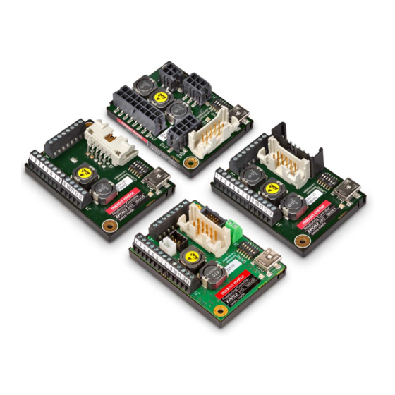
Maxon Motor EPOS2 24/2 Digital Controller Manuals
Manuals and User Guides for Maxon Motor EPOS2 24/2 Digital Controller. We have
1
Maxon Motor EPOS2 24/2 Digital Controller manual available for free PDF download: Hardware Reference Manual
Maxon Motor EPOS2 24/2 Hardware Reference Manual (48 pages)
Positioning Controller
Brand:
Maxon Motor
| Category:
Controller
| Size: 4 MB
Table of Contents
T Cable Ofcontents 1 about this Document 5 2 Introduction 7
3
Table of Contents
3
Table 3-11 Table
3
Table 1-1 Table
5
About this Document
5
Figure 2-1 Documentation Structure
7
Documentation Structure
7
Safety Precautions
8
Table 31-34 Electrical Data 1-3 Rating
9
Table 3-5 Electrical Data - Inputs
9
Electrical Data
9
Table 3-6 Electrical Data - Outputs
9
Table 3-7 Electrical Data - Voltage Outputs
10
Table 3-8 Electrical Data - Motor Connections
10
Table 3-9 Electrical Data - Connections
10
Figure 3-2 Dimensional Drawing [MM] - DC (390438)
11
Mechanical Data
11
Table 3-10 Electrical Data - Interfaces
11
Figure 3-3 Dimensional Drawing [MM] - DC/EC (390003)
12
Figure 3-4 Dimensional Drawing [MM] - DCX (530239)
12
Figure 3-5 Dimensional Drawing [MM] - EC (380264)
12
Environmental Conditions
13
Figure 3-6 Derating Output Current
13
Order Details
13
Table 3-13 Environmental Conditions
13
Table 3-14 Order Details
13
Standards
14
Table 3-15 Standards
14
Wiring Diagrams
15
EPOS2 24/2 for Maxon DC Motors (390438)
15
Figure 4-7 Interfaces - Designations and Location «DC» (390438)
15
Figure 4-8 Wiring Diagram «DC» (390438)
15
EPOS2 24/2 for Maxon DC/EC Motors (390003)
16
Figure 4-9 Interfaces - Designations and Location «DC/EC» (390003)
16
Figure 4-10 Wiring Diagram «DC/EC» (390003)
16
EPOS2 24/2 for Maxon DCX Motors (530239)
17
Figure 4-11 Interfaces - Designations and Location «DCX» (530239)
17
Figure 4-12 Wiring Diagram «DCX» (530239)
17
EPOS2 24/2 for Maxon EC Motors (380264)
18
Figure 4-13 Interfaces - Designations and Location «EC» (380264)
18
Figure 4-14 Wiring Diagram «EC» (380264)
18
Table 4-16 Controller Types and Their Connectors
19
Supply/Control Signals Connector (J1)
20
Figure 4-15 Supply/Control Signals Connector (J1)
20
Figure 4-16 Digin1
21
Figure 4-17 Digin2 (Analogously Valid also for Digin3)
21
Figure 4-18 Digin4 (Analogously Valid also for Digin5/6)
22
Figure 4-19 Digin4 - Type PNP Proximity Switch (Analogously Valid also for Digin5/6)
22
Figure 4-20 Digin4 - Photoelectric Sensor (Analogously Valid also for Digin5/6)
23
Figure 4-21 Digout3 Circuit (Analogously Valid also for Digout4)
24
Figure 4-22 Digout3 "Sinks" Circuit (Analogously Valid also for Digout4)
24
Figure 4-23 Digout3 "Source" Circuit (Analogously Valid also for Digout4)
25
Communication/Analog Inputs Connector (J2)
27
Figure 4-24 Communication/Analog Inputs Connector (J2)
27
Figure 4-25 Anin1 Circuit (Analogously Valid also for Anin2)
28
Motor/Encoder Connector (J3)
29
Figure 4-26 Motor/Encoder Connector (J3)
29
Figure 4-27 Encoder Input Circuit Channel a (Analogously Valid also for Channel B/Index)
29
Encoder Connector (J4)
30
Motor Connectors (J5 / J6 / J7)
30
Figure 4-28 Encoder Connector (J4)
30
Figure 4-29 Motor Connectors (J5, Left) / (J6, Center) / (J7, Right)
30
Motor/Hall Sensors Connector (J8)
31
Figure 4-30 Motor/Hall Sensors Connector (J8)
31
Figure 4-31 Hall Sensor Input Circuit
31
Encoder Connector (J9)
32
Figure 4-32 Encoder Connector (J9)
32
Motor/Hall Sensors Connector (J10)
33
Figure 4-33 Motor/Hall Sensors Connector (J10)
33
Encoder Connector (J11)
34
Figure 4-34 Encoder Connector (J11)
34
Figure 4-35 Controller PCB - Solder Pads
34
RS232 Connector (J12)
35
Figure 4-36 RS232 Connector (J12)
35
CAN Connector (J13)
36
Figure 4-37 CAN Connector (J13)
36
Supply/Control Signals Connector (J14)
37
Figure 4-38 Supply/Control Signals Connector (J14)
37
USB Connector (J15)
38
Figure 4-39 USB Connector (J15)
38
Connectors
19
CAN Node Identification (JP1)
39
CAN ID (Node Address)
39
Table 4-17 CAN ID - Binary Code Values
39
Table 4-18 CAN ID - DIP Switch Settings (Example)
39
CAN Bus Termination
40
Table 4-19 Leds - Interpretation of Condition
40
EPOS2 24/2 Hardware Reference Edition: November
41
CAN Bit Rate Detection
40
Status Leds
40
Figure 4-40 DIP Switch (JP1 [6]) - CAN Bus Termination (Left "OFF" / Right "ON")
40
Figure 4-41 DIP Switch (JP1 [5]) - Auto Bit Rate (Left "OFF" / Right "ON")
40
L Fist Ofigures
43
Advertisement
Advertisement
Related Products
Maxon Motor EPOS2 70/10
Maxon Motor EPOS2 50/5
Maxon Motor EPOS2 P 24/5
Maxon Motor EPOS2 Module 36/2
maxon motor EPOS 24/1
maxon motor EPOS 24/5
maxon motor EPOS2 24/5
Maxon Motor EPOS4 Module 50/8
Maxon Motor EPOS4 Compact 50/8 EtherCAN
Maxon Motor EPOS4 50/5
Maxon Motor Categories
Controller
Amplifier
DC Drives
Control Unit
Engine
More Maxon Motor Manuals
Login
Sign In
OR
Sign in with Facebook
Sign in with Google
Upload manual
Upload from disk
Upload from URL