Sign In
Upload
Manuals
Brands
Juniper Manuals
Network Hardware
JRR200
Juniper JRR200 Route Reflector System Manuals
Manuals and User Guides for Juniper JRR200 Route Reflector System. We have
3
Juniper JRR200 Route Reflector System manuals available for free PDF download: Hardware Manual, Quick Start Manual
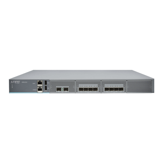
Juniper JRR200 Hardware Manual (108 pages)
Route Reflector
Brand:
Juniper
| Category:
Network Router
| Size: 2 MB
Table of Contents
Table of Contents
3
About the Documentation
11
Documentation and Release Notes
11
Documentation Conventions
11
Table 1: Notice Icons
12
Table 2: Text and Syntax Conventions
12
Documentation Feedback
13
About the Documentation
13
Requesting Technical Support
14
Opening a Case with JTAC
14
Self-Help Online Tools and Resources
14
Chapter 1 Overview
17
JRR200 Route Reflector Overview
17
JRR200 Route Reflector System Overview
17
JRR200 Route Reflector Field-Replaceable Units
17
JRR200 Chassis
18
JRR200 Route Reflector Chassis Front Panel
18
Figure 1: JRR200 Route Reflector Front Panel
18
Table 3: JRR200 Route Reflector Components on the Front Panel
18
Figure 2: JRR200 Route Reflector Chassis Status Leds
19
JRR200 Route Reflector Chassis Status Leds
19
Management Port Leds
19
Table 4: JRR200 Route Reflector Chassis Status Leds
19
Table 5: Management Port Leds
19
Network Port Leds
20
JRR200 Route Reflector Chassis Rear Panel
20
Figure 3: Network Port Leds
20
Figure 4: JRR200 Route Reflector Rear Panel
20
Table 6: Network Port Leds
20
Table 7: JRR200 Route Reflector Rear Panel Components
20
JRR200 Route Reflector Physical Specifications
21
JRR200 Route Reflector Cooling System
21
Table 8: Physical Specifications of the JRR200 Route Reflector Chassis
21
JRR200 Route Reflector Air Flow and Cooling System
22
JRR200 Power System
22
Figure 5: Airflow through the Chassis
22
Figure 6: AC Power Supply Unit
23
Figure 7: AC Power Supply Unit Leds
23
JRR200 Route Reflector AC Power Supply
23
JRR200 Route Reflector AC Power Supply Specifications
24
Table 10: AC Power Supply Specifications
24
Table 9: AC Power Supply Unit Leds
24
Figure 8: AC Plug Types
25
JRR200 Route Reflector AC Power Cord Specifications
25
Table 11: AC Power Cord Specifications
25
Figure 10: DC Power Supply Leds
26
Figure 9: DC Power Supply Unit
26
JRR200 Route Reflector DC Power Supply
26
JRR200 Route Reflector DC Power Supply Specifications
27
Table 12: DC Power Supply Unit Leds
27
Table 13: DC Power Supply Specifications
27
Chapter 2 Site Planning, Preparation, and Specifications
29
Site Preparation Checklist for the JRR200 Route Reflector
29
Table 14: Site Preparation Checklist for JRR200 Route Reflector
29
JRR200 Site Guidelines and Requirements
30
JRR200 Route Reflector Environmental Specifications
30
Table 15: Environmental Specifications
30
General Site Guidelines
31
Site Electrical Wiring Guidelines
31
Site Planning, Preparation, and Specifications
31
Clearance Requirements for JRR200 Route Reflector Airflow and Hardware Maintenance
32
Table 16: Site Electrical Wiring Guidelines
32
Figure 11: Airflow through the Chassis
33
Site Planning, Preparation, and Specifications
33
Table 17: Clearance Requirements for the JRR200 Route Reflector
33
JRR200 Rack and Cabinet Requirements
34
JRR200 Route Reflector Cabinet Requirements
34
JRR200 Route Reflector Rack Requirements
34
Table 18: Rack Requirements
34
JRR200 Network Cable and Transceiver Planning
35
Pluggable Transceivers Supported on JRR200 Route Reflector
35
Table 19: Cabinet Requirements and Specifications
35
SFP+ Direct Attach Copper Cables for JRR200 Route Reflector
36
JRR200 Management and Console Port Connector Pinout Specifications
36
Console Port Connector Pinout Information for the JRR200 Route
36
Management Port Connector Pinout Information for the JRR200 Route
36
Reflector
36
Table 20: Management Port Connector Pinout Information
36
Reflector
37
Table 21: Console Port Connector Pinout Information
37
Chapter 3 Initial Installation and Configuration
39
JRR200 Route Reflector Installation Overview
39
Overview
39
Unpacking the JRR200
40
Unpacking the JRR200 Route Reflector
40
Verifying Parts Received with the JRR200 Route Reflector
40
Installing the JRR200 Route Reflector in a Rack
41
Table 22: Parts List for a Fully Configured JRR200 Route Reflector
41
Figure 12: Attaching the Mounting Ears and Fixed Brackets
42
Connecting the JRR200 to Power
43
Connect the Grounding Cable
43
Figure 13: Securing the Mounting Ears to the Rack
43
Figure 14: Attaching the Adjustable Brackets
43
Connecting Power to an AC-Powered JRR200 Route Reflector
44
Connecting Power to a DC-Powered JRR200 Route Reflector
46
Connecting JRR200 Route Reflector to External Devices
47
Connecting JRR200 Route Reflector to Management Devices
48
Performing the Initial Configuration for JRR200
48
JRR200 Route Reflector Initial Configuration Using the CLI
49
JRR200 Route Reflector Factory-Default Settings
50
Viewing Factory-Default Settings of JRR200 Route Reflector
52
Chapter 4 Maintaining Components
53
Maintaining the JRR200 Chassis
53
Routine Maintenance Procedures for the JRR200 Route Reflector
53
Maintaining the JRR200 Cooling System
53
Maintaining the Fan Trays on the JRR200 Route Reflector
53
Replacing the JRR200 Route Reflector Fan Tray
54
Figure 15: JRR200 Route Reflector Fan Tray Numbering
54
Maintaining the JRR200 Power System
55
Maintaining the JRR200 Route Reflector Power Supplies
55
Replacing the JRR200 Route Reflector AC Power Supply
56
Removing a JRR200 Route Reflector AC Power Supply
56
Figure 16: Removing an AC Power Supply
57
Installing a JRR200 Route Reflector AC Power Supply
57
Replacing the JRR200 Route Reflector DC Power Supply
58
Figure 17: Installing an AC Power Supply
58
Removing a JRR200 Route Reflector DC Power Supply
58
Figure 18: Removing a DC Power Supply
59
Installing a JRR200 Route Reflector DC Power Supply
59
Maintaining the JRR200 Cables and Connectors
60
Maintaining JRR200 Route Reflector Network Cables
60
Figure 19: Installing a DC Power Supply
60
Replacing an SFP+ Transceiver on JRR200 Route Reflector
61
Figure 20: Small Form-Factor Pluggable (SFP) Transceiver
61
Removing an SFP+ Transceiver
61
Installing an SFP+ Transceiver
62
Chapter 5 Troubleshooting Hardware
65
Troubleshooting the JRR200
65
Troubleshooting Resources for JRR200 Route Reflector
65
Chassis Component Alarm Conditions on JRR200 Route Reflector
65
Table 23: Alarms for JRR200 Route Reflector Chassis Components
66
Troubleshooting Hardware
67
Chapter 6 Contactingcustomersupportandreturningthechassisor
69
Components
69
Returning the JRR200 Chassis or Components
69
Returning a JRR200 Route Reflector or Hardware Component to Juniper
69
Networks
69
Listing the JRR200 Route Reflector Component Details with the CLI
70
Component
70
Locating the Chassis Serial Number ID Label
71
Locating the Serial Number ID Labels on Frus
71
Contacting Customer Support
71
Packing a JRR200 Route Reflector or Its Components for Shipping
71
Packing the JRR200 Route Reflector for Shipment
72
Packing the JRR200 Route Reflector Components for Shipment
73
Chapter 7 Safety and Compliance Information
75
General Safety Guidelines and Warnings
76
Definitions of Safety Warning Levels
77
Restricted Access Warning
78
Fire Safety Requirements
80
Fire Suppression
80
Fire Suppression Equipment
80
Qualified Personnel Warning
81
Warning Statement for Norway and Sweden
81
Installation Instructions Warning
82
Chassis and Component Lifting Guidelines
82
Ramp Warning
83
Rack-Mounting and Cabinet-Mounting Warnings
83
Grounded Equipment Warning
87
Laser and LED Safety Guidelines and Warnings
88
General Laser Safety Guidelines
88
Class 1 Laser Product Warning
88
Class 1 LED Product Warning
89
Laser Beam Warning
89
Radiation from Open Port Apertures Warning
90
Maintenance and Operational Safety Guidelines and Warnings
91
Battery Handling Warning
91
Jewelry Removal Warning
92
Lightning Activity Warning
93
Operating Temperature Warning
94
Product Disposal Warning
95
General Electrical Safety Guidelines and Warnings
96
Prevention of Electrostatic Discharge Damage
97
AC Power Electrical Safety Guidelines
98
Figure 21: Placing a Component into an Antistatic Bag
98
AC Power Disconnection Warning
99
DC Power Disconnection Warning
100
DC Power Grounding Requirements and Warning
101
DC Power Wiring Sequence Warning
102
DC Power Wiring Terminations Warning
103
Multiple Power Supplies Disconnection Warning
104
TN Power Warning
105
Action to Take after an Electrical Accident
106
JRR200 Agency Approvals and Regulatory Compliance Information
106
Agency Approvals
106
Acoustic Noise Compliance Statements
107
EMC Requirements
108
Canada
108
European Community
108
Israel
108
Japan
108
United States
108
Advertisement
Juniper JRR200 Hardware Manual (127 pages)
Route Reflector
Brand:
Juniper
| Category:
Network Hardware
| Size: 2 MB
Table of Contents
Table of Contents
3
About this Guide
8
Overview
9
JRR200 Route Reflector Overview
10
JRR200 Route Reflector System Overview
10
JRR200 Route Reflector Field-Replaceable Units
10
JRR200 Chassis
11
JRR200 Route Reflector Chassis Front Panel
11
JRR200 Route Reflector Chassis Rear Panel
15
JRR200 Route Reflector Physical Specifications
16
JRR200 Route Reflector Cooling System
17
JRR200 Route Reflector Air Flow and Cooling System
17
JRR200 Power System
18
JRR200 Route Reflector AC Power Supply
19
JRR200 Route Reflector AC Power Supply Specifications
20
JRR200 Route Reflector AC Power Cord Specifications
21
JRR200 Route Reflector DC Power Supply
23
JRR200 Route Reflector DC Power Supply Specifications
24
Site Planning, Preparation, and Specifications
26
Site Preparation Checklist for the JRR200 Route Reflector
27
JRR200 Site Guidelines and Requirements
28
JRR200 Route Reflector Environmental Specifications
29
General Site Guidelines
29
Site Electrical Wiring Guidelines
30
Clearance Requirements for JRR200 Route Reflector Airflow and Hardware Maintenance
31
JRR200 Rack and Cabinet Requirements
32
JRR200 Route Reflector Rack Requirements
32
JRR200 Route Reflector Cabinet Requirements
33
JRR200 Network Cable and Transceiver Planning
34
Pluggable Transceivers Supported on JRR200 Route Reflector
35
SFP+ Direct Attach Copper Cables for JRR200 Route Reflector
35
JRR200 Management and Console Port Connector Pinout Specifications
36
Management Port Connector Pinout Information for the JRR200 Route Reflector
36
Console Port Connector Pinout Information for the JRR200 Route Reflector
37
Initial Installation and Configuration
39
JRR200 Route Reflector Installation Overview
40
Installing and Connecting an JRR200 Route Reflector Installation Overview
40
Unpacking the JRR200
41
Unpacking the JRR200 Route Reflector
41
Verifying Parts Received with the JRR200 Route Reflector
41
Installing the JRR200 Route Reflector in a Rack
43
Connecting the JRR200 to Power
46
Connect the Grounding Cable
46
Connecting Power to an AC-Powered JRR200 Route Reflector
47
Connecting Power to a DC-Powered JRR200 Route Reflector
49
Connecting JRR200 Route Reflector to External Devices
51
Connecting JRR200 Route Reflector to Management Devices
51
Performing the Initial Configuration for JRR200
52
JRR200 Route Reflector Initial Configuration Using the CLI
52
JRR200 Route Reflector Factory-Default Settings
54
Viewing Factory-Default Settings of JRR200 Route Reflector
56
Maintaining Components
58
Maintaining the JRR200 Chassis
59
Routine Maintenance Procedures for the JRR200 Route Reflector
59
Maintaining the JRR200 Cooling System
59
Maintaining the Fan Trays on the JRR200 Route Reflector
60
Replacing the JRR200 Route Reflector Fan Tray
61
Maintaining the JRR200 Power System
62
Maintaining the JRR200 Route Reflector Power Supplies
62
Replacing the JRR200 Route Reflector AC Power Supply
63
Removing a JRR200 Route Reflector AC Power Supply
64
Installing a JRR200 Route Reflector AC Power Supply
65
Replacing the JRR200 Route Reflector DC Power Supply
66
Removing a JRR200 Route Reflector DC Power Supply
66
Installing a JRR200 Route Reflector DC Power Supply
67
Maintaining the JRR200 Cables and Connectors
68
Maintaining JRR200 Route Reflector Network Cables
68
Replacing an SFP+ Transceiver on JRR200 Route Reflector
70
Removing an SFP+ Transceiver
70
Installing an SFP+ Transceiver
71
Troubleshooting Hardware
73
Troubleshooting the JRR200
74
Troubleshooting Resources for JRR200 Route Reflector
74
Chassis Component Alarm Conditions on JRR200 Route Reflector
74
Contacting Customer Support and Returning the Chassis or Components
79
Returning the JRR200 Chassis or Components
80
Returning a JRR200 Route Reflector or Hardware Component to Juniper Networks
80
Listing the JRR200 Route Reflector Component Details with the CLI
81
Locating the Serial Number on the JRR200 Route Reflector or Component
82
Locating the Chassis Serial Number ID Label
82
Locating the Serial Number ID Labels on Frus
82
Contacting Customer Support
82
Packing a JRR200 Route Reflector or Its Components for Shipping
83
Support" on Page
83
Packing the JRR200 Route Reflector for Shipment
84
Packing the JRR200 Route Reflector Components for Shipment
84
Safety and Compliance Information
86
General Safety Guidelines and Warnings
88
Definitions of Safety Warning Levels
89
Restricted Access Warning
91
Fire Safety Requirements
92
Qualified Personnel Warning
93
Warning Statement for Norway and Sweden
94
Installation Instructions Warning
94
Chassis and Component Lifting Guidelines
95
Ramp Warning
96
Rack-Mounting and Cabinet-Mounting Warnings
96
Grounded Equipment Warning
100
Laser and LED Safety Guidelines and Warnings
101
Radiation from Open Port Apertures Warning
104
Maintenance and Operational Safety Guidelines and Warnings
105
General Electrical Safety Guidelines and Warnings
111
Prevention of Electrostatic Discharge Damage
112
AC Power Electrical Safety Guidelines
114
AC Power Disconnection Warning
115
DC Power Disconnection Warning
116
DC Power Grounding Requirements and Warning
117
DC Power Wiring Sequence Warning
118
DC Power Wiring Terminations Warning
120
Multiple Power Supplies Disconnection Warning
121
TN Power Warning
122
Action to Take after an Electrical Accident
122
JRR200 Agency Approvals and Regulatory Compliance Information
123
Agency Approvals
123
Acoustic Noise Compliance Statements
125
EMC Requirements
125
Juniper JRR200 Quick Start Manual (10 pages)
Route Reflector
Brand:
Juniper
| Category:
Network Hardware
| Size: 1 MB
Table of Contents
Table of Contents
1
JRR200 Route Reflector Overview
1
Package Contents
1
Register the Product
2
JRR200 Route Reflector Chassis Overview
2
Mount the JRR200 Route Reflector on Four Posts of a Rack
3
Connect the Grounding Cable
4
Power on the JRR200 Route Reflector
5
Connect to the Console
7
Initial Configuration Using the CLI
8
Power off the Device
9
Reset the Configuration
9
Safety Warnings Summary
9
Reference
9
Advertisement
Advertisement
Related Products
Juniper Junos OS
Juniper JATP700
Juniper PowerConnect J-SRX210
Juniper J4350
Juniper J2300
Juniper J-Series
Juniper JUNOSE 11.0.X PHYSICAL LAYER
Juniper JUNOS OS 10.4
Juniper JUNOS 10.2
Juniper JSA3500
Juniper Categories
Network Router
Switch
Gateway
Software
Network Hardware
More Juniper Manuals
Login
Sign In
OR
Sign in with Facebook
Sign in with Google
Upload manual
Upload from disk
Upload from URL