Table of Contents
Advertisement
Quick Links
Advertisement
Table of Contents
Troubleshooting

Related Manuals for Juniper JRR200


Summary of Contents for Juniper JRR200
- Page 1 JRR200 Route Reflector Hardware Guide Published 2022-11-29...
- Page 2 The Juniper Networks product that is the subject of this technical documentation consists of (or is intended for use with) Juniper Networks software. Use of such software is subject to the terms and conditions of the End User License Agreement ("EULA") posted at https:/ /support.juniper.net/support/eula/.
-
Page 3: Table Of Contents
Site Preparation Checklist for the JRR200 Route Reflector | 19 JRR200 Site Guidelines and Requirements | 20 JRR200 Route Reflector Environmental Specifications | 21 General Site Guidelines | 21 Site Electrical Wiring Guidelines | 22 Clearance Requirements for JRR200 Route Reflector Airflow and Hardware Maintenance | 23... - Page 4 SFP+ Direct Attach Copper Cables for JRR200 Route Reflector | 27 JRR200 Management and Console Port Connector Pinout Specifications | 28 Management Port Connector Pinout Information for the JRR200 Route Reflector | 28 Console Port Connector Pinout Information for the JRR200 Route Reflector | 29...
- Page 5 Contacting Customer Support and Returning the Chassis or Components Returning the JRR200 Chassis or Components | 72 Returning a JRR200 Route Reflector or Hardware Component to Juniper Networks | 72 Listing the JRR200 Route Reflector Component Details with the CLI | 73...
- Page 6 Contacting Customer Support | 74 Packing a JRR200 Route Reflector or its Components for Shipping | 75 Packing the JRR200 Route Reflector for Shipment | 76 Packing the JRR200 Route Reflector Components for Shipment | 76 Safety and Compliance Information...
- Page 7 Multiple Power Supplies Disconnection Warning | 113 TN Power Warning | 114 Action to Take After an Electrical Accident | 114 JRR200 Agency Approvals and Regulatory Compliance Information | 115 Agency Approvals | 115 Acoustic Noise Compliance Statements | 117...
-
Page 8: About This Guide
About This Guide Use this guide to install hardware and perform initial software configuration, routine maintenance, and troubleshooting for the JRR200 Route Reflector. After completing the installation and basic configuration procedures covered in this guide, refer to the Junos OS documentation for information about further software configuration. -
Page 9: Overview
C HAPTER Overview JRR200 Route Reflector Overview | 2 JRR200 Chassis | 3 JRR200 Route Reflector Cooling System | 9 JRR200 Power System | 10... -
Page 10: Jrr200 Route Reflector Overview
JRR200 Route Reflector Field-Replaceable Units | 2 JRR200 Route Reflector System Overview The Juniper Networks JRR200 Route Reflector is a 1U form factor appliance with a multicore x86 CPU and preinstalled vRR software that can host one route reflector instance. The JRR200 route reflector is suitable for large enterprises, data centers and service providers for hosting vRR software to scale up to 30 million routing information base (RIB) entries. -
Page 11: Jrr200 Chassis
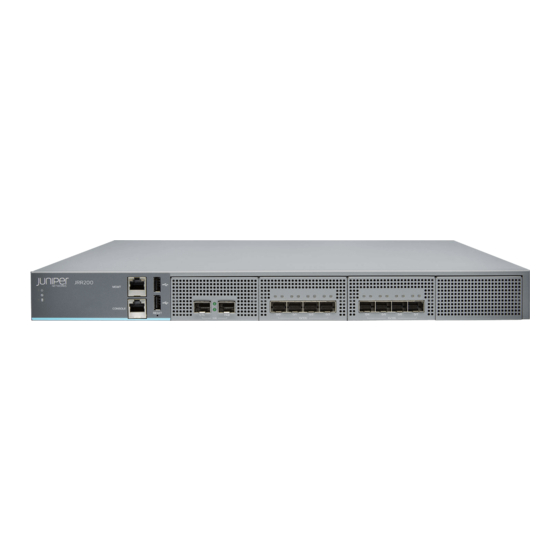
Network Port LEDs | 6 Figure 1 on page 3 shows the front panel of the JRR200 route reflector. Figure 1: JRR200 Route Reflector Front Panel Table 1 on page 4 lists the components on the front panel of the JRR200 route reflector. - Page 12 Returns the JRR200 route reflector to the factory-default configuration. JRR200 Route Reflector Chassis Status LEDs Figure 2 on page 4 shows the chassis status LEDs that are located on the front panel of the JRR200 route reflector. Table 2 on page 5 describes the LEDs.
- Page 13 Table 2: JRR200 Route Reflector Chassis Status LEDs Description Power • Solid green—receiving power Status • Solid green—operating normally • Solid red—critical alarm • Hardware component failure • Software module failure • Fan failure (atleast one) • Blinking red—noncritical alarm •...
- Page 14 (Continued) Table 3: Management Port LEDs Description Speed (LED on the right) • Solid green—100-Mbps link is established. • Solid amber—1000-Mbps link is established. • Off—There is no link established. Network Port LEDs Each SFP+ port has two status LEDs located above the port. Table 4 on page 6 describes the LEDs.
-
Page 15: Jrr200 Route Reflector Chassis Rear Panel
Connects the JRR200 route reflector chassis to earth ground. Power switch Use the Power switch to power on or power off the JRR200 route reflector. Alarm Off button Use this button to turn off an alarm triggered because of an abnormal DC output voltage caused by any of the following: •... -
Page 16: Jrr200 Route Reflector Physical Specifications
JRR200 route reflector with 2 AC power supplies: 29 lb (13.16 kg) • JRR200 route reflector with 2 DC power supplies: 28.8 lb (13.06 kg) You can mount the JRR200 route reflector on a standard 19-in. four-post rack or in a standard 19-in. enclosed cabinet. -
Page 17: Jrr200 Route Reflector Cooling System
JRR200 Route Reflector Air Flow and Cooling System The cooling system for the JRR200 Route Reflector consists of four fan trays located at the rear of the chassis. Each fan tray contains two fans, so there are a total of eight fans. The fans draw cool air through vents on the front of the chassis and exhaust the air through the back of the chassis. -
Page 18: Jrr200 Power System
The fan tray is a field-replaceable unit (FRU)and you can install it without powering off the JRR200 route reflector or disrupting the route reflector function. Figure 5: Airflow Through the Chassis JRR200 Power System IN THIS SECTION JRR200 Route Reflector AC Power Supply | 11... -
Page 19: Jrr200 Route Reflector Ac Power Supply
JRR200 Route Reflector AC Power Supply The JRR200 Route Reflector is shipped with two redundant AC power supply units pre-installed in the rear panel of the chassis. The AC power supply unit is a field-replaceable unit (FRU) and you can install it without powering off the JRR200 route reflector or disrupting the route reflector function. -
Page 20: Jrr200 Route Reflector Ac Power Supply Specifications
• If the AC LED is lit and the DC LED is unlit, the AC power supply unit is installed properly, but the power supply unit has an internal failure. JRR200 Route Reflector AC Power Supply Specifications Table 8 on page 13... -
Page 21: Jrr200 Route Reflector Ac Power Cord Specifications
1500 BTU/Hour Note: 1 W = 3.41 BTU/Hour JRR200 Route Reflector AC Power Cord Specifications A detachable AC power cord is supplied with the AC power supplies. The coupler is type C13 as described by International Electrotechnical Commission (IEC) standard 60320. - Page 22 BS 1363A Figure 8: AC Plug Types NOTE: Power cords and cables must not block access to the JRR200 route reflector components or drape where people might trip on them. CAUTION: The AC power cord for the JRR200 route reflector is intended for use with...
-
Page 23: Jrr200 Route Reflector Dc Power Supply
JRR200 Route Reflector DC Power Supply The JRR200 Route Reflector is shipped with two redundant DC power supply units pre-installed in the rear panel of the chassis. The DC power supply unit is a field-replaceable unit (FRU) and you can install it without powering off the JRR200 route reflector or disrupting the route reflector function. -
Page 24: Jrr200 Route Reflector Dc Power Supply Specifications
On steadily Power supply unit failure. Blinking Invalid power supply unit. Unlit Power supply unit is functioning normally. JRR200 Route Reflector DC Power Supply Specifications Table 11 on page 17 lists the power supply specifications for a DC power supply. - Page 25 Table 11: DC Power Supply Specifications Item Specifications DC input voltage • Minimum operating voltage: –40 VDC • Nominal operating voltage: –48 VDC • Operating voltage range: –40 VDC through –72 VDC DC input current rating 9 A maximum at nominal operating voltage Output power 650 W...
-
Page 26: Site Planning, Preparation, And Specifications
C HAPTER Site Planning, Preparation, and Specifications Site Preparation Checklist for the JRR200 Route Reflector | 19 JRR200 Site Guidelines and Requirements | 20 JRR200 Rack and Cabinet Requirements | 24 JRR200 Network Cable and Transceiver Planning | 26 JRR200 Management and Console Port Connector Pinout Specifications | 28... -
Page 27: Site Preparation Checklist For The Jrr200 Route Reflector
Table 12 on page 19 provides a checklist of tasks you need to perform when preparing a site for installing the JRR200 Route Reflector. Table 12: Site Preparation Checklist for JRR200 Route Reflector Item or Task Additional Information Performed By... -
Page 28: Jrr200 Site Guidelines And Requirements
Plan the cable routing and management. JRR200 Site Guidelines and Requirements IN THIS SECTION JRR200 Route Reflector Environmental Specifications | 21 General Site Guidelines | 21 Site Electrical Wiring Guidelines | 22 Clearance Requirements for JRR200 Route Reflector Airflow and Hardware Maintenance | 23... -
Page 29: Jrr200 Route Reflector Environmental Specifications
JRR200 Route Reflector Environmental Specifications Table 13 on page 21 provides the required environmental conditions for normal JRR200 Route Reflector operations. In addition, the site must be as dust-free as possible because dust can clog air intake vents, reducing the efficiency of the cooling system. -
Page 30: Site Electrical Wiring Guidelines
Site Electrical Wiring Guidelines Table 14 on page 22 describes the factors you must consider while planning the electrical wiring at your site. WARNING: You must provide a properly grounded and shielded environment and use electrical surge-suppression devices. Avertissement Vous devez établir un environnement protégé et convenablement mis à la terre et utiliser des dispositifs de parasurtension. -
Page 31: Clearance Requirements For Jrr200 Route Reflector Airflow And Hardware Maintenance
Figure 11: Airflow Through the Chassis • If you are mounting the JRR200 route reflector on a rack or cabinet along with other equipment, ensure that the exhaust from other equipment does not blow into the intake vents of the chassis. -
Page 32: Jrr200 Rack And Cabinet Requirements
JRR200 Route Reflector Rack Requirements | 24 JRR200 Route Reflector Cabinet Requirements | 25 JRR200 Route Reflector Rack Requirements The JRR200 Route Reflector is designed to be installed on four-post racks. Table 16 on page 25 provides the rack requirements and specifications for the route reflector. -
Page 33: Jrr200 Route Reflector Cabinet Requirements
EIA-310–D) published by the Electronics Industry Association (http:/ /www.eia.org). • The rack must be strong enough to support the weight of the JRR200 route reflector. • Ensure that the spacing of rails and adjacent racks provides for proper clearance around the JRR200 route reflector and rack. -
Page 34: Jrr200 Network Cable And Transceiver Planning
Cabinet Guideline Requirement Cabinet size You can mount the JRR200 route reflector in a cabinet that contains a 19-in. rack as defined in Cabinets, Racks, Panels, and Associated Equipment (document number EIA-310–D) published by the Electronics Industry Association (http:/ /www.ecianow.org/standards- practices/standards/). -
Page 35: Pluggable Transceivers Supported On Jrr200 Route Reflector
Small form-factor pluggable plus transceiver (SFP+) direct attach copper (DAC) cables are suitable for short distances of up to 23 ft (7 m), making them ideal for highly cost-effective networking connectivity within a rack and between adjacent racks. The JRR200 Route Reflector supports the following 1 m and 3 m long DAC cables:... -
Page 36: Jrr200 Management And Console Port Connector Pinout Specifications
The port on the front panel labeled MGMT is an autosensing 10/100/1000-Mbps Ethernet RJ-45 receptacle that accepts an Ethernet cable for connecting the JRR200 Route Reflector to a management LAN (or other device that supports out-of-band management). Two LEDs on the port indicate link activity on the port and the administrative status of the port. -
Page 37: Console Port Connector Pinout Information For The Jrr200 Route Reflector
Termination network Termination network Termination network Console Port Connector Pinout Information for the JRR200 Route Reflector The console port is an RS-232 serial interface that uses an RJ-45 connector to connect to a console management device. The default baud rate for the console port is 9600 baud. - Page 38 (Continued) Table 19: Console Port Connector Pinout Information Signal Description Ground Signal Ground Ground Signal Ground Receive Data DSR/DCD Data Set Ready Clear to Send...
-
Page 39: Initial Installation And Configuration
Initial Installation and Configuration JRR200 Route Reflector Installation Overview | 32 Unpacking the JRR200 | 33 Installing the JRR200 Route Reflector in a Rack | 35 Connecting the JRR200 to Power | 38 Connecting JRR200 Route Reflector to External Devices | 43... -
Page 40: Jrr200 Route Reflector Installation Overview
"Connecting Power to an AC-Powered JRR200 Route Reflector" on page 39 • "Connecting Power to a DC-Powered JRR200 Route Reflector" on page 41 6. Connect the JRR200 route reflector to external devices as described in "Connecting JRR200 Route Reflector to External Devices" on page 7. -
Page 41: Unpacking The Jrr200
4. Verify the parts received against the inventory (packing list). The packing list specifies the part numbers and carries a brief description of each part in your order. 5. Save the shipping carton and packing materials in case you need to move or ship the JRR200 route reflector at a later time. - Page 42 /www.juniper.net/support/ requesting-support.html NOTE: The parts shipped with your JRR200 route reflector can vary depending on the configuration you ordered. Table 20 on page 34 lists the parts and their quantities in the packing list.
-
Page 43: Installing The Jrr200 Route Reflector In A Rack
You can mount the route reflector on four posts in a 19-in. rack or cabinet by using the rack-mount kit shipped with the device. (The remainder of this topic uses rack to mean rack or cabinet.) Before mounting the JRR200 route reflector on four posts in a rack: 1. Verify that the site meets the requirements described in "Site Preparation Checklist for the JRR200... - Page 44 2. Have one person grasp both sides of the JRR200 route reflector, lift it, and position it in the rack so that the front mounting bracket holes align with the threaded holes in the rack rail and the second...
- Page 45 JRR200 route reflector to the rack by using rack-mounting screws (and cage nuts and washers if your rack requires them). Figure 13: Securing the Mounting Ears to the Rack 3. Continue to support the JRR200 route reflector, and have the second person slide the rear mounting blades into the channels of the side mounting rails and secure the blades to the rack.
-
Page 46: Connecting The Jrr200 To Power
• One metric M5 x 10 mm grounding screw To meet safety and electromagnetic interference (EMI) requirements and to ensure proper operation, the JRR200 Route Reflector must be adequately grounded before power is connected. You must provide a grounding lug to connect the route reflector to earth ground. -
Page 47: Connecting Power To An Ac-Powered Jrr200 Route Reflector
3. Place the grounding cable lug over the grounding point on the rear of the chassis. NOTE: The JRR200 route reflector should be permanently connected to ground during normal operation. A licensed electrician must attach a cable lug to the grounding cable. A cable with an incorrectly attached lug can damage the JRR200 route reflector. - Page 48 1. Attach an electrostatic discharge (ESD) grounding strap to your bare wrist, and connect the strap to the ESD point on the rear of the chassis. 2. Locate the power cords shipped with the JRR200 route reflector; the cords have plugs appropriate for your geographical location.
-
Page 49: Connecting Power To A Dc-Powered Jrr200 Route Reflector
• If there is no power switch on the AC power source outlet, set the power switch on the JRR200 route reflector to the on (|) position and it will power on. 9. Verify that the AC and DC LEDs on each power supply are lit green. - Page 50 Ensure that the voltage across the DC power source cable leads is 0 V and that the cable leads do not become active while you are connecting DC power. Verify that the DC power cables are correctly labeled before making connections to the power supply.
-
Page 51: Connecting Jrr200 Route Reflector To External Devices
1. Attach an electrostatic discharge (ESD) grounding strap to your bare wrist, and connect the strap to the ESD point on the chassis. 2. Plug one end of the RJ-45 cable into the CONSOLE port of the JRR200 route reflector and the other end into the DB-9 serial port adapter. -
Page 52: Performing The Initial Configuration For Jrr200
• Flow control—None Performing the Initial Configuration for JRR200 IN THIS SECTION JRR200 Route Reflector Initial Configuration Using the CLI | 44 JRR200 Route Reflector Factory-Default Settings | 46 Viewing Factory-Default Settings of JRR200 Route Reflector | 48 JRR200 Route Reflector Initial Configuration Using the CLI Access the CLI to perform the initial configuration. - Page 53 7. Connect the MGMT port on the device to the Ethernet port on the management device using an RJ-45 cable. 8. The JRR200 route reflector MGMT port is internally mapped to the em0 interface in Junos. By default, the management network interface (em0) is configured with DHCP enabled. If there is a DHCP server on the management network, then the JRR200 management network interface is automatically assigned an IP address.
-
Page 54: Jrr200 Route Reflector Factory-Default Settings
JRR200 Route Reflector Factory-Default Settings Your JRR200 route reflector comes configured with a factory-default configuration which has the ZTP configurations enabled when the JRR200 route reflector is shipped. The below is the factory default configuration file of JRR200 route reflector. - Page 55 interfaces { em4 { unit 0 { family inet { dhcp; interfaces { em5 { unit 0 { family inet { dhcp; interfaces { em6 { unit 0 { family inet { dhcp; interfaces { em7 { unit 0 { family inet { dhcp;...
-
Page 56: Viewing Factory-Default Settings Of Jrr200 Route Reflector
Viewing Factory-Default Settings of JRR200 Route Reflector To view the factory-default settings on your JRR200 route reflector: 1. Log in as the root user and provide your credentials. 2. View the list of default config files:... - Page 57 3. View the required default config file. user@host> file show /etc/config/<config file name> When you commit changes to the configuration, a new configuration file is created, which becomes the active configuration. If the current active configuration fails, you can use the load factory-default command to revert to the factory-default configuration.
-
Page 58: Maintaining Components
C HAPTER Maintaining Components Maintaining the JRR200 Chassis | 51 Maintaining the JRR200 Cooling System | 51 Maintaining the JRR200 Power System | 54 Maintaining the JRR200 Cables and Connectors | 60... -
Page 59: Maintaining The Jrr200 Chassis
• Inspect the installation site for moisture, loose wires or cables, and excessive dust. • Make sure that airflow is unobstructed around the JRR200 route reflector and into the air intake vents. Make sure that all power and grounding cables are arranged so that they do not obstruct access to other device components. -
Page 60: Maintaining The Fan Trays On The Jrr200 Route Reflector
Action • Monitor the status of the fan trays. All the fan trays work in unison to cool the JRR200 route reflector. If one fan trayfails, the redundant fan tray acts as a backup. A major alarm is triggered when a fan fails, and a minor alarm and major alarm is triggered when a fan tray is removed. -
Page 61: Replacing The Jrr200 Route Reflector Fan Tray
Replacing the JRR200 Route Reflector Fan Tray Each fan tray is a field-replaceable unit (FRU) installed in the rear panel of JRR200 route reflector. You can remove and replace the fan trays without powering off JRR200 route reflector or disrupting route reflector functions. -
Page 62: Maintaining The Jrr200 Power System
Maintaining the JRR200 Power System IN THIS SECTION Maintaining the JRR200 Route Reflector Power Supplies | 54 Replacing the JRR200 Route Reflector AC Power Supply | 55 Replacing the JRR200 Route Reflector DC Power Supply | 58 Maintaining the JRR200 Route Reflector Power Supplies... -
Page 63: Replacing The Jrr200 Route Reflector Ac Power Supply
Installing a JRR200 Route Reflector AC Power Supply | 57 Each AC power supply is a field-replaceable unit (FRU) installed in the rear panel of JRR200 route reflector. You can remove and replace the power supplies without powering off JRR200 route reflector... -
Page 64: Removing A Jrr200 Route Reflector Ac Power Supply
• ESD grounding strap • Antistatic bag or an antistatic mat • Replacement power supply To remove a power supply from JRR200 route reflector (see Figure 1. Place the antistatic bag or the antistatic mat on a flat, stable surface. -
Page 65: Installing A Jrr200 Route Reflector Ac Power Supply
4. Using both hands, place the power supply in the power supply slot on the rear panel of the JRR200 route reflector and slide it in until it is fully seated and the ejector lever fits into place. You will hear a distinct click when the power supply is fully seated in the chassis. -
Page 66: Replacing The Jrr200 Route Reflector Dc Power Supply
Installing a JRR200 Route Reflector DC Power Supply | 59 Each DC power supply is a field-replaceable unit (FRU) installed in the rear panel of the JRR200 device. You can remove and replace the power supplies without powering off the JRR200 device or disrupting route reflector functions. -
Page 67: Installing A Jrr200 Route Reflector Dc Power Supply
Figure 18: Removing a DC Power Supply 10. Place the power supply in the antistatic bag or on the antistatic mat placed on a flat, stable surface. Installing a JRR200 Route Reflector DC Power Supply Ensure that you have the following parts and tools available: •... -
Page 68: Maintaining The Jrr200 Cables And Connectors
Figure 19: Installing a DC Power Supply Maintaining the JRR200 Cables and Connectors IN THIS SECTION Maintaining JRR200 Route Reflector Network Cables | 60 Replacing an SFP+ Transceiver on JRR200 Route Reflector | 62 Maintaining JRR200 Route Reflector Network Cables IN THIS SECTION Purpose | 61... - Page 69 • Label both ends of the cables to identify them. The following guidelines apply specifically to fiber-optic cables that connect to optical transceivers that are installed in Juniper Networks devices: • When you unplug a fiber-optic cable, always cover the cable connector with the rubber safety cap.
-
Page 70: Replacing An Sfp+ Transceiver On Jrr200 Route Reflector
Replacing an SFP+ Transceiver on JRR200 Route Reflector IN THIS SECTION Removing an SFP+ Transceiver | 62 Installing an SFP+ Transceiver | 63 Small form-factor pluggable plus transceivers (SFP+) are enhanced SFP transceivers that provides support for data rates of up to 10 Gbps for fiber-optic or copper interfaces. You can remove and replace the SFP+ transceivers without powering off the device or disrupting device functions. -
Page 71: Installing An Sfp+ Transceiver
LASER WARNING: Do not look directly into a fiber-optic transceiver or into the ends of fiber-optic cables. Fiber-optic transceivers and fiber-optic cables connected to a transceiver emit laser light that can damage your eyes. 5. Pull the ejector handle out from the transceiver to unlock the transceiver. CAUTION: Make sure that you open the ejector handle completely until you hear it click. - Page 72 5. Slide the transceiver until the connector is seated in the component slot. If you are unable to fully insert the transceiver, make sure the connector is facing the right way. 6. Close the ejector handle of the transceiver. 7. Remove the rubber safety cap from the transceiver and the end of the cable. Insert the cable into the transceiver.
-
Page 73: Troubleshooting Hardware
C HAPTER Troubleshooting Hardware Troubleshooting the JRR200 | 66... -
Page 74: Troubleshooting The Jrr200
Troubleshooting Resources for JRR200 Route Reflector To troubleshoot JRR200 route reflector, use the command-line interface (CLI) and LEDs on the chassis: • LEDs—When the JRR200 route reflector detects an alarm condition, the status LED on the front panel glows red. - Page 75 Table 21: Alarms for JRR200 Route Reflector Chassis Components Component Alarm Conditions Action Alarm Severity At least one of the fans Steady red (major) • Check and adjust the room have failed. temperature, if possible. • Check the air flow and...
- Page 76 (Continued) Table 21: Alarms for JRR200 Route Reflector Chassis Components Component Alarm Conditions Action Alarm Severity Missing fan tray Install the missing fan tray. Red (major) Fan over-speeding Yellow (minor) • Check if the fan is spinning more than the configured speed.
- Page 77 (Continued) Table 21: Alarms for JRR200 Route Reflector Chassis Components Component Alarm Conditions Action Alarm Severity Input failure to the power Red (major) • Check the voltage of the supply power source if it is in the operating range. •...
- Page 78 (Continued) Table 21: Alarms for JRR200 Route Reflector Chassis Components Component Alarm Conditions Action Alarm Severity Power supply internal Red (major) • Replace the power supply. devices failure. • Open a support case using the Case Manager link at https:/ /www.juniper.net/...
-
Page 79: Contacting Customer Support And Returning The Chassis Or Components
C HAPTER Contacting Customer Support and Returning the Chassis or Components Returning the JRR200 Chassis or Components | 72... -
Page 80: Returning The Jrr200 Chassis Or Components
To return a JRR200 route reflector or hardware component to Juniper Networks for repair or replacement, follow this procedure: 1. Determine the part number and serial number of the JRR200 route reflector or component. See "Locating the Serial Number on the JRR200 Route Reflector or Component" on page 2. -
Page 81: Listing The Jrr200 Route Reflector Component Details With The Cli
Before contacting Juniper Networks to request a Return Materials Authorization (RMA), you must find the serial number on the JRR200 route reflector or component. To list all the JRR200 route reflector components and their serial numbers, enter the following CLI command: user@host>... -
Page 82: Locating The Serial Number On The Jrr200 Route Reflector Or Component
Locating the Serial Number ID Labels on FRUs | 74 If you are returning a device or hardware component to Juniper Networks for repair or replacement, you must locate the serial number of the device or component. You must provide the serial number to the Juniper Networks Technical Assistance Center (JTAC) when you contact them to obtain Return Materials Authorization (RMA). -
Page 83: Packing A Jrr200 Route Reflector Or Its Components For Shipping
• Your existing service request number, if you have one • Details of the failure or problem • Type of activity being performed on the JRR200 route reflector when the problem occurred • Configuration data displayed by one or more show commands •... -
Page 84: Packing The Jrr200 Route Reflector For Shipment
Disconnect power cables from the JRR200 route reflector. Remove the cables that connect to all external devices. If the JRR200 route reflector is installed in a rack, have one person support the weight of the route reflector while another person unscrews and removes the mounting screws. - Page 85 • Write the Return Materials Authorization (RMA) number on the exterior of the box to ensure proper tracking. CAUTION: Do not stack any of the JRR200 route reflector components during packing.
-
Page 86: Safety And Compliance Information
C HAPTER Safety and Compliance Information General Safety Guidelines and Warnings | 80 Definitions of Safety Warning Levels | 81 Restricted Access Warning | 83 Fire Safety Requirements | 84 Qualified Personnel Warning | 85 Warning Statement for Norway and Sweden | 86 Installation Instructions Warning | 86 Chassis and Component Lifting Guidelines | 87 Ramp Warning | 88... - Page 87 DC Power Wiring Sequence Warning | 110 DC Power Wiring Terminations Warning | 112 Multiple Power Supplies Disconnection Warning | 113 TN Power Warning | 114 Action to Take After an Electrical Accident | 114 JRR200 Agency Approvals and Regulatory Compliance Information | 115...
-
Page 88: General Safety Guidelines And Warnings
General Safety Guidelines and Warnings The following guidelines help ensure your safety and protect the device from damage. The list of guidelines might not address all potentially hazardous situations in your working environment, so be alert and exercise good judgment at all times. •... -
Page 89: Definitions Of Safety Warning Levels
• Some parts of the chassis, including AC and DC power supply surfaces, power supply unit handles, SFB card handles, and fan tray handles might become hot. The following label provides the warning for hot surfaces on the chassis: • Always ensure that all modules, power supplies, and cover panels are fully inserted and that the installation screws are fully tightened. - Page 90 Waarschuwing Dit waarschuwingssymbool betekent gevaar. U verkeert in een situatie die lichamelijk letsel kan veroorzaken. Voordat u aan enige apparatuur gaat werken, dient u zich bewust te zijn van de bij elektrische schakelingen betrokken risico's en dient u op de hoogte te zijn van standaard maatregelen om ongelukken te voorkomen. Varoitus Tämä...
-
Page 91: Restricted Access Warning
Restricted Access Warning WARNING: This unit is intended for installation in restricted access areas. A restricted access area is an area to which access can be gained only by service personnel through the use of a special tool, lock and key, or other means of security, and which is controlled by the authority responsible for the location. -
Page 92: Fire Safety Requirements
In addition, you should establish procedures to protect your equipment in the event of a fire emergency. Juniper Networks products should be installed in an environment suitable for electronic equipment. We recommend that fire suppression equipment be available in the event of a fire in the vicinity of the equipment and that all local fire, safety, and electrical codes and ordinances be observed when you install and operate your equipment. -
Page 93: Qualified Personnel Warning
NOTE: To keep warranties effective, do not use a dry chemical fire extinguisher to control a fire at or near a Juniper Networks device. If a dry chemical fire extinguisher is used, the unit is no longer eligible for coverage under a service agreement. -
Page 94: Warning Statement For Norway And Sweden
Varoitus Ainoastaan koulutettu ja pätevä henkilökunta saa asentaa tai vaihtaa tämän laitteen. Avertissement Tout installation ou remplacement de l'appareil doit être réalisé par du personnel qualifié et compétent. Warnung Gerät nur von geschultem, qualifiziertem Personal installieren oder auswechseln lassen. Avvertenza Solo personale addestrato e qualificato deve essere autorizzato ad installare o sostituire questo apparecchio. -
Page 95: Chassis And Component Lifting Guidelines
Waarschuwing Raadpleeg de installatie-aanwijzingen voordat u het systeem met de voeding verbindt. Varoitus Lue asennusohjeet ennen järjestelmän yhdistämistä virtalähteeseen. Avertissement Avant de brancher le système sur la source d'alimentation, consulter les directives d'installation. Warnung Lesen Sie die Installationsanweisungen, bevor Sie das System an die Stromquelle anschließen. -
Page 96: Ramp Warning
• Above 121.2 lb (55 kg): Use material handling systems (such as levers, slings, lifts, and so on). When this is not practical, engage specially trained persons or systems (such as riggers or movers). Ramp Warning WARNING: When installing the device, do not use a ramp inclined at more than 10 degrees. - Page 97 De onderstaande richtlijnen worden verstrekt om uw veiligheid te verzekeren: • De Juniper Networks switch moet in een stellage worden geïnstalleerd die aan een bouwsel is verankerd. • Dit toestel dient onderaan in het rek gemonteerd te worden als het toestel het enige in het rek is.
- Page 98 • Le rack sur lequel est monté le Juniper Networks switch doit être fixé à la structure du bâtiment. • Si cette unité constitue la seule unité montée en casier, elle doit être placée dans le bas. • Si cette unité est montée dans un casier partiellement rempli, charger le casier de bas en haut en plaçant l'élément le plus lourd dans le bas.
- Page 99 Para garantizar su seguridad, proceda según las siguientes instrucciones: • El Juniper Networks switch debe instalarse en un bastidor fijado a la estructura del edificio.
-
Page 100: Grounded Equipment Warning
Följande riktlinjer ges för att trygga din säkerhet: • Juniper Networks switch måste installeras i en ställning som är förankrad i byggnadens struktur. • Om denna enhet är den enda enheten på ställningen skall den installeras längst ned på... -
Page 101: Laser And Led Safety Guidelines And Warnings
Class 1 LED Product Warning | 95 Laser Beam Warning | 95 Juniper Networks devices are equipped with laser transmitters, which are considered a Class 1 Laser Product by the U.S. Food and Drug Administration and are evaluated as a Class 1 Laser Product per IEC/EN 60825-1 requirements. - Page 102 General Laser Safety Guidelines When working around ports that support optical transceivers, observe the following safety guidelines to prevent eye injury: • Do not look into unterminated ports or at fibers that connect to unknown sources. • Do not examine unterminated optical ports with optical instruments. •...
- Page 103 Class 1 LED Product Warning LASER WARNING: Class 1 LED product. Waarschuwing Klasse 1 LED-product. Varoitus Luokan 1 valodiodituote. Avertissement Alarme de produit LED Class I. Warnung Class 1 LED-Produktwarnung. Avvertenza Avvertenza prodotto LED di Classe 1. Advarsel LED-produkt i klasse 1. Aviso Produto de classe 1 com LED.
-
Page 104: Radiation From Open Port Apertures Warning
Aviso Não olhe fixamente para o raio, nem olhe para ele directamente com instrumentos ópticos. ¡Atención! No mirar fijamente el haz ni observarlo directamente con instrumentos ópticos. Varning! Rikta inte blicken in mot strålen och titta inte direkt på den genom optiska instrument. -
Page 105: Maintenance And Operational Safety Guidelines And Warnings
EXposição à radiação e não deverá olhar fixamente para orifícios que se encontrarem a descoberto. ¡Atención! Debido a que la apertura del puerto puede emitir radiación invisible cuando no existe un cable de fibra conectado, evite mirar directamente a las aperturas para no exponerse a la radiación. - Page 106 Waarschuwing Er is ontploffingsgevaar als de batterij verkeerd vervangen wordt. Vervang de batterij slechts met hetzelfde of een equivalent type dat door de fabrikant aanbevolen is. Gebruikte batterijen dienen overeenkomstig fabrieksvoorschriften weggeworpen te worden. Varoitus Räjähdyksen vaara, jos akku on vaihdettu väärään akkuun. Käytä vaihtamiseen ainoastaan saman- tai vastaavantyyppistä...
- Page 107 Jewelry Removal Warning WARNING: Before working on equipment that is connected to power lines, remove jewelry, including rings, necklaces, and watches. Metal objects heat up when connected to power and ground and can cause serious burns or can be welded to the terminals. Waarschuwing Alvorens aan apparatuur te werken die met elektrische leidingen is verbonden, sieraden (inclusief ringen, kettingen en horloges) verwijderen.
- Page 108 ¡Atención! Antes de operar sobre equipos conectados a líneas de alimentación, quitarse las joyas (incluidos anillos, collares y relojes). Los objetos de metal se calientan cuando se conectan a la alimentación y a tierra, lo que puede ocasionar quemaduras graves o que los objetos metálicos queden soldados a los bornes.
- Page 109 6 in. (15.2 cm) of clearance around the ventilation openings. Waarschuwing Om te voorkomen dat welke switch van de Juniper Networks router dan ook oververhit raakt, dient u deze niet te bedienen op een plaats waar de maximale aanbevolen omgevingstemperatuur van 40°...
- Page 110 ¡Atención! Para impedir que un encaminador de la serie Juniper Networks switch se recaliente, no lo haga funcionar en un área en la que se supere la temperatura ambiente máxima recomendada de 40° C. Para impedir la restricción de la entrada de aire, deje un espacio mínimo de 15,2 cm alrededor de las aperturas para ventilación.
-
Page 111: General Electrical Safety Guidelines And Warnings
General Electrical Safety Guidelines and Warnings WARNING: Certain ports on the device are designed for use as intrabuilding (within- GR-1089-CORE ) the-building) interfaces only (Type 2 or Type 4 ports as described in and require isolation from the exposed outside plant (OSP) cabling. To comply with NEBS (Network Equipment-Building System) requirements and protect against lightning must not be surges and commercial power disturbances, the intrabuilding ports... -
Page 112: Prevention Of Electrostatic Discharge Damage
• Canada—Canadian Electrical Code, Part 1, CSA C22.1. • Suitable for installation in Information Technology Rooms in accordance with Article 645 of the National Electrical Code and NFPA 75. Peut être installé dans des salles de matériel de traitement de l’information conformément à l’article 645 du National Electrical Code et à... - Page 113 If a grounding strap is not available, hold the component in its antistatic bag (see Figure 21 on page 105) in one hand and touch the exposed, bare metal of the device with the other hand immediately before inserting the component into the device. WARNING: For safety, periodically check the resistance value of the ESD grounding strap.
-
Page 114: Ac Power Electrical Safety Guidelines
CAUTION: ANSI/TIA/EIA-568 cables such as Category 5e and Category 6 can get electrostatically charged. To dissipate this charge, always ground the cables to a suitable and safe earth ground before connecting them to the system. Attention Les câbles ANSI/TIA/EIA-568, par exemple Cat 5e et Cat 6, peuvent emmagasiner des charges électrostatiques. -
Page 115: Ac Power Disconnection Warning
Power Cable Warning (Japanese) WARNING: The attached power cable is only for this product. Do not use the cable for another product. AC Power Disconnection Warning WARNING: Before working on the device or near power supplies, unplug all the power cords from an AC-powered device. -
Page 116: Dc Power Disconnection Warning
¡Atención! Antes de manipular el chasis de un equipo o trabajar cerca de una fuente de alimentación, desenchufar el cable de alimentación en los equipos de corriente alterna (CA). Varning! Innan du arbetar med ett chassi eller nära strömförsörjningsenheter skall du för växelströmsenheter dra ur nätsladden. -
Page 117: Dc Power Grounding Requirements And Warning
Avvertenza Prima di svolgere una qualsiasi delle procedure seguenti, verificare che il circuito CC non sia alimentato. Per verificare che tutta l'alimentazione sia scollegata (OFF), individuare l'interruttore automatico sul quadro strumenti che alimenta il circuito CC, mettere l'interruttore in posizione OFF e fissarlo con nastro adesivo in tale posizione. -
Page 118: Dc Power Wiring Sequence Warning
Waarschuwing Bij de installatie van het toestel moet de aardverbinding altijd het eerste worden gemaakt en het laatste worden losgemaakt. Varoitus Laitetta asennettaessa on maahan yhdistäminen aina tehtävä ensiksi ja maadoituksen irti kytkeminen viimeiseksi. Avertissement Lors de l'installation de l'appareil, la mise à la terre doit toujours être connectée en premier et déconnectée en dernier. - Page 119 Avertissement Câblez l'approvisionnement d'alimentation CC En utilisant les crochets appropriés à l'extrémité de câblage. En reliant la puissance, l'ordre approprié de câblage est rectifié pour rectifier, +RTN à +RTN, puis –48 V à –48 V. En débranchant la puissance, l'ordre approprié de câblage est –48 V à –48 V, +RTN à +RTN, a alors rectifié pour rectifier.
-
Page 120: Dc Power Wiring Terminations Warning
DC Power Wiring Terminations Warning WARNING: When stranded wiring is required, use approved wiring terminations, such as closed-loop or spade-type with upturned lugs. These terminations must be the appropriate size for the wires and must clamp both the insulation and conductor. Waarschuwing Wanneer geslagen bedrading vereist is, dient u bedrading te gebruiken die voorzien is van goedgekeurde aansluitingspunten, zoals het gesloten-lus type of het grijperschop type waarbij de aansluitpunten omhoog wijzen. -
Page 121: Multiple Power Supplies Disconnection Warning
¡Atención! Cuando se necesite hilo trenzado, utilizar terminales para cables homologados, tales como las de tipo "bucle cerrado" o "espada", con las lengüetas de conexión vueltas hacia arriba. Estos terminales deberán ser del tamaño apropiado para los cables que se utilicen, y tendrán que sujetar tanto el aislante como el conductor. Varning! När flertrådiga ledningar krävs måste godkända ledningskontakter användas, t.ex. -
Page 122: Tn Power Warning
¡Atención! Esta unidad tiene más de una conexión de suministros de alimentación; para eliminar la alimentación por completo, deben desconectarse completamente todas las conexiones. Varning! Denna enhet har mer än en strömförsörjningsanslutning; alla anslutningar måste vara helt avlägsnade innan strömtillförseln till enheten är fullständigt bruten. TN Power Warning WARNING: The device is designed to work with a TN power system. -
Page 123: Jrr200 Agency Approvals And Regulatory Compliance Information
Agency Approvals IN THIS SECTION Compliance Statement for Argentina | 117 The JRR200 Route Reflector complies with the following standards: • Safety • CAN/CSA C22.2 No. 60950-1-07, 2nd Edition, 2014-10 • EN 60950-1:2006 + A11:2009 + A1:2010 + A12:2011 + A2:2013 •... - Page 124 • CAN/CSA C22.2 No. 62368-1-14 • EN 62368-1: 2014+A11: 2017 • UL 62368-1: 2014 • IEC 62368-1:2014 (Second Edition) • IEC 60950-1:2005 (Second Edition); Am1:2009 + Am2:2013 • CE • EMC • FCC Part 15 Class A (2007) USA Radiated Emissions •...
-
Page 125: Acoustic Noise Compliance Statements
• 1KV / 2KV surge required (no 4KV / DT) • ROHS • Reduction of Hazardous Substances (ROHS) 6 • Telco • Common Language Equipment Identifier (CLEI) code • NEBS • Not compliant Compliance Statement for Argentina EQUIPO DE USO IDÓNEO. Acoustic Noise Compliance Statements The maximum emitted sound pressure level is 70 dB(A) or less per EN ISO 7779. - Page 126 VCCI-A United States The JRR200 Route Reflector has been tested and found to comply with the limits for a Class A digital device of the FCC Rules. These limits are designed to provide reasonable protection against harmful...
- Page 127 interference when the equipment is operated in a commercial environment. This equipment generates, uses, and can radiate radio frequency energy and, if not installed and used in accordance with the instruction manual, may cause harmful interference to radio communications. Operation of this equipment in a residential area is likely to cause harmful interference in which case the user will be required to correct the interference at his own expense.
Need help?
Do you have a question about the JRR200 and is the answer not in the manual?
Questions and answers