Sign In
Upload
Manuals
Brands
IEI Technology Manuals
Motherboard
IMBA-Q170-i2
IEI Technology IMBA-Q170-i2 Manuals
Manuals and User Guides for IEI Technology IMBA-Q170-i2. We have
1
IEI Technology IMBA-Q170-i2 manual available for free PDF download: User Manual
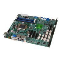
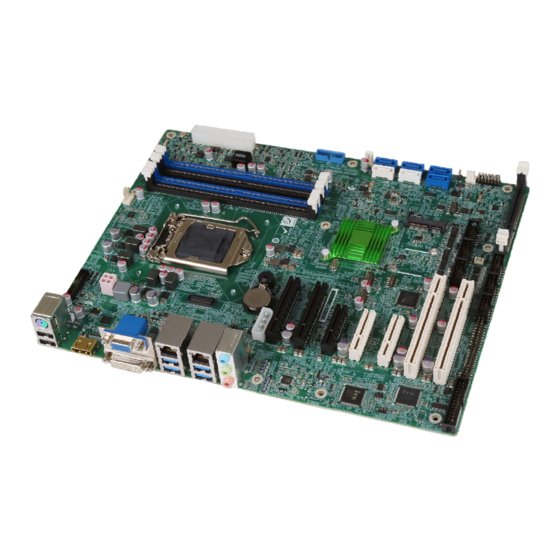
IEI Technology IMBA-Q170-i2 User Manual (182 pages)
ATX motherboard supports 14nm LGA1151 IntelR CPU IntelR Q170
Brand:
IEI Technology
| Category:
Motherboard
| Size: 11.86 MB
Table of Contents
User Manual
1
Table of Contents
5
Introduction
17
Introduction
18
Figure 1-1: IMBA-Q170-I2
18
Features
19
Connectors
20
Figure 1-2: Connectors
20
Dimensions
21
Figure 1-3: IMBA-Q170-I2 Dimensions (MM)
21
Data Flow
22
Figure 1-4: Data Flow Diagram
22
Technical Specifications
23
Table 1-1: IMBA-Q170-I2 Specifications
25
Packing List
26
Anti-Static Precautions
27
Unpacking Precautions
27
Packing List
28
Optional Items
29
Table 2-1: Packing List
29
Table 2-2: Optional Items
31
Connectors
32
Peripheral Interface Connectors
33
IMBA-Q170-I2 Layout
33
Figure 3-1: Peripheral Interface Connectors
33
Peripheral Interface Connectors
34
External Interface Panel Connectors
35
Table 3-1: Peripheral Interface Connectors
35
Internal Peripheral Connectors
36
ATX Power Connector
36
Figure 3-2: +12V ATX Power Connector Pinout Location
36
Table 3-2: Rear Panel Connectors
36
Table 3-3: +12V ATX Power Connector Pinouts
36
Additional Power Connector
37
ATX Power Connector
37
Figure 3-3: Additional Power Connector Location
37
Table 3-4: Additional Power Connector Pinouts
37
Figure 3-4: ATX Power Connector Location
38
Table 3-5: ATX Power Connector Pinouts
38
Battery Connector
39
Figure 3-5: Battery Connector Location
39
Chassis Intrusion Connector
40
Figure 3-6: Chassis Intrusion Connector Location
40
Table 3-6: Chassis Intrusion Connector Pinouts
40
DDR4 DIMM Slots
41
Figure 3-7: DDR4 DIMM Slot Locations
41
Digital I/O Connector
42
Figure 3-8: Digital I/O Connector Location
42
Table 3-7: Digital I/O Connector Pinouts
42
EC Debug Connector
43
Figure 3-9: EC Debug Connector Location
43
Table 3-8: EC Debug Connector Pinouts
43
Fan Connector (CPU)
44
Figure 3-10: CPU Fan Connector Location
44
Table 3-9: CPU Fan Connector Pinouts
44
Fan Connectors (System)
45
Figure 3-11: System Fan Connector Locations
45
Table 3-10: System Fan (SYS_FAN1) Connector Pinouts
45
Table 3-11: System Fan (SYS_FAN2) Connector Pinouts
45
Front Panel Audio Connector
46
Figure 3-12: Front Panel Audio Connector Location
46
Table 3-12: Front Panel Audio Connector Pinouts
46
Front Panel Connector
47
Figure 3-13: Front Panel Connector Location
47
Table 3-13: Front Panel Connector Pinouts
47
I 2 C Connector
48
Figure 3-14: I 2 C Connector Location
48
Table 3-14: I 2 C Connector Pinouts
48
Internal Displayport Connector
49
Figure 3-15: Internal Displayport Connector Location
49
Table 3-15: Internal Displayport Connector Pinouts
49
Iris Module Slot
50
Figure 3-16: Iris Module Slot Location
50
Keyboard and Mouse Connector
51
Figure 3-17: Keyboard and Mouse Connector Location
51
Table 3-16: Keyboard and Mouse Connector Pinouts
51
LAN LED Connectors
52
Figure 3-18: LAN LED Connector Locations
52
Table 3-17: LAN1 LED Connector (LED_LAN1) Pinouts
52
Table 3-18: LAN2 LED Connector (LED_LAN2) Pinouts
52
Parallel Port Connector
53
Figure 3-19: Parallel Port Connector Location
53
PCI Slots
54
Pcie X4 Slots
54
Figure 3-20: PCI Slot Locations
54
Table 3-19: Parallel Port Connector Pinouts
54
Pcie X8 Slots
55
Figure 3-21: Pcie X4 Slot Locations
55
Figure 3-22: Pcie X8 Slot Locations
55
Pcie Mini Slot
56
Figure 3-23: Pcie Mini Slot Location
56
Power Button
57
Table 3-20: Pcie Mini Slot Pinouts
57
SATA 6Gb/S Drive Connector
58
Figure 3-24: Power Button Location
58
Serial Port Connectors, RS-232
59
Figure 3-25: SATA 6Gb/S Drive Connector Locations
59
Table 3-21: SATA 6Gb/S Drive Connector Pinouts
59
Serial Port Connectors, RS-232/422/485
60
Figure 3-26: RS-232 Serial Port Connector Location
60
Table 3-22: RS-232 Serial Port Connector Pinouts
60
Figure 3-27: RS-232/422/485 Connector Location
61
Table 3-23: RS-232/422/485 Connector Pinouts
61
Table 3-24: DB-9 RS-232/422/485 Pinouts
61
Smbus Connector
62
Figure 3-28: Smbus Connector Location
62
Table 3-25: Smbus Connector Pinouts
62
SPI Flash Connector
63
Figure 3-29: SPI Flash Connector Location
63
Table 3-26: SPI Flash Connector Pinouts
63
SPI Flash Connector, EC
64
Figure 3-30: SPI EC Flash Connector Location
64
Table 3-27: SPI EC Flash Connector Pinouts
64
TPM Connector
65
Figure 3-31: TPM Connector Location
65
Table 3-28: TPM Connector Pinouts
65
USB 2.0 Connectors
66
Figure 3-32: USB 2.0 Connector Pinout Locations
66
Table 3-29: USB 2.0 Connector Pinouts
66
USB 3.0 Connector
67
Figure 3-33: USB 3.0 Connector Location
67
Table 3-30: USB 3.0 Connector Pinouts
67
External Peripheral Interface Connector Panel
68
Audio Connector
68
Figure 3-34: External Peripheral Interface Connector
68
Ethernet and USB 3.0 Connectors
69
Figure 3-35: Audio Connector
69
Table 3-31: USB 3.0 Port Pinouts
69
HDMI Connector
70
Table 3-32: LAN Pinouts
70
Table 3-33: HDMI Connector Pinouts
70
Keyboard/Mouse and USB 2.0 Connectors
71
Table 3-34: USB 2.0 Port Pinouts
71
Table 3-35: PS/2 Connector Pinouts
71
VGA and DVI-D Connectors
72
Table 3-36: DVI-D Connector Pinouts
72
Figure 3-36: VGA Connector
73
Table 3-37: VGA Connector Pinouts
73
Installation
74
Anti-Static Precautions
75
Installation Considerations
75
Socket Lga1151 Cpu Installation
77
Figure 4-1: Disengage the CPU Socket Load Lever
77
Figure 4-2: Remove Protective Cover
78
Figure 4-3: Insert the Socket LGA1151 CPU
79
Figure 4-4: Close the Socket LGA1151
79
Socket Lga1151 Cooling Kit Installation
80
Figure 4-5: Cooling Kit Support Bracket
81
DIMM Installation
82
Figure 4-6: DIMM Installation
82
Iris Module Installation
83
Figure 4-7: Iris Module Installation
83
Full-Size Pcie Mini Card Installation
84
Figure 4-8: Removing the Retention Screw
84
Figure 4-9: Inserting the Full-Size Pcie Mini Card into the Slot at an Angle
85
Figure 4-10: Securing the Full-Size Pcie Mini Card
85
Half-Size Pcie Mini Card Installation
86
Figure 4-11: Installing the Standoff
86
Usb 3.0 Expansion Card Installation
87
Figure 4-12: Inserting the Half-Size Pcie Mini Card into the Slot at an Angle
87
Figure 4-13: Securing the Half-Size Pcie Mini Card
87
Pcie Mini and Msata Expansion Card Installation
88
Figure 4-14: PCIEX4_2 Slot and USB Header Locations
88
Figure 4-15: PCIEX4_3 Slot Location
89
System Configuration
90
AT/ATX Power Mode Setting
90
Figure 4-16: AT/ATX Power Mode Switch Location
90
Table 4-1: AT/ATX Power Mode Switch Settings
90
Clearing CMOS
91
Figure 4-17: Clear CMOS Button and Header Locations
91
Switching BIOS
92
Figure 4-18: BIOS1/BIOS2 Switch Location
92
Table 4-2: BIOS1/BIOS2 Switch Settings
92
Flexible I/O Configuration
93
Table 4-3: Flexible I/O Configuration
93
Flash Descriptor Security Override Jumper
94
Figure 4-19: Flash Descriptor Security Override Jumper Location
94
Table 4-4: Flash Descriptor Security Override Jumper Settings
94
Msata Setup
95
Figure 4-20: Msata Setup Jumper Location
95
Table 4-5: Msata Setup Jumper Settings
95
USB Power Selection
96
Internal Peripheral Device Connections
96
SATA Drive Connection
96
Table 4-6: BIOS Options and Configured USB Ports
96
Table 4-7: USB Power Source Setup
96
Figure 4-21: SATA Drive Cable Connection
97
Adding Usb 3.0 Drivers to a Windows 7 Installation Image
98
Figure 4-22: SATA Power Drive Connection
98
Figure 4-23: Windows 7 USB 3.0 Creator Utility
99
Intel ® Amt Setup Procedure
100
Figure 4-24: Update Process Is Complete
100
Ipmi Setup Procedure
101
Managed System Hardware Setup
101
Using the IEI Iman Web GUI
101
Figure 4-25: IEI Iman Web Address
102
Figure 4-26: IEI Iman Web GUI
103
Bios
104
Introduction
105
Starting Setup
105
Using Setup
105
Getting Help
106
Unable to Reboot after Configuration Changes
106
Table 5-1: BIOS Navigation Keys
106
BIOS Menu Bar
107
Main
107
BIOS Menu 1: Main
108
Advanced
109
Trusted Computing
110
ACPI Settings
111
AMT Configuration
112
Super IO Configuration
113
Serial Port N Configuration
114
Serial Port 1 Configuration
114
Serial Port 2 Configuration
115
Serial Port 3 Configuration
116
Parallel Port Configuration
120
Iwdd H/W Monitor
122
Smart Fan Mode Configuration
123
RTC Wake Settings
124
Serial Port Console Redirection
126
Legacy Console Redirection Settings
129
CPU Configuration
130
SATA Configuration
132
Nvme Configuration
133
USB Configuration
134
Iei Feature
135
Chipset
136
System Agent (SA) Configuration
137
Graphics Configuration
138
PEG Port Configuration
139
Memory Configuration
140
PCH-IO Configuration
141
PCI Express Configuration
142
Table 5-2: BIOS Options and Configured USB Ports
142
Table 5-3: BIOS Options with Correspondent I/O Configuration
142
BIOS Menu 25: PCI Express Configuration (for BIOS1)
143
BIOS Menu 26: PCI Express Configuration (for BIOS2)
144
BIOS Menu 27: PCIEX1_1 Slot and PCIEX4_1 Slot Configuration Menu
145
HD Audio Configuration
146
Security
147
Boot
148
Save & Exit
150
BIOS Menu 31: Save & Exit
150
Server Mgmt
151
System Event Log
151
BMC Network Configuration
153
Software Drivers
155
Available Software Drivers
156
Software Installation
156
Figure 6-1: Introduction Screen
157
A Regulatory Compliance
158
B Product Disposal
160
CBIOS Options
162
D Terminology
166
E Digital I/O Interface
170
Introduction
171
Assembly Language Sample
172
Assembly Language Sample 2
172
F Watchdog Timer
173
G Intel® Matrix Storage Manager
176
Introduction
177
Precautions
177
Features and Benefits
178
Accessing the Intel® Matrix Storage Manager
178
Installing the Operating System to the Raid Array
179
H Hazardous Materials Disclosure
180
Advertisement
Advertisement
Related Products
iEi Technology IMBA-Q454-R10
IEI Technology IMBA-Q670
IEI Technology IMBA-Q770
IEI Technology IMBA-Q870-i2
IEI Technology IMBA-Q370
IEI Technology IMBA-Q470-R10
IEI Technology IMBA-Q370-R20
IEI Technology IMBA-Q370-R10
IEI Technology IMB-ADL-Q670
IEI Technology IMB-ADL-H610
IEI Technology Categories
Motherboard
Touch Panel
Computer Hardware
Single board computers
Desktop
More IEI Technology Manuals
Login
Sign In
OR
Sign in with Facebook
Sign in with Google
Upload manual
Upload from disk
Upload from URL