Sign In
Upload
Manuals
Brands
IDEC Manuals
Computer Hardware
MICROSMART FC6A-PC4
IDEC MICROSMART FC6A-PC4 Cartridge Manuals
Manuals and User Guides for IDEC MICROSMART FC6A-PC4 Cartridge. We have
1
IDEC MICROSMART FC6A-PC4 Cartridge manual available for free PDF download: User Manual
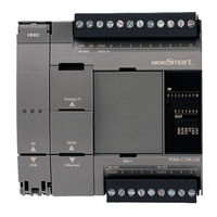
IDEC MICROSMART FC6A-PC4 User Manual (578 pages)
Brand:
IDEC
| Category:
Computer Hardware
| Size: 39.96 MB
Table of Contents
Safety Precautions
2
About this Manual
4
About the Warranty of the Products
6
Related Manuals
7
Table of Contents
9
Hapter
10
About the FC6A Series Microsmart
13
Features
20
Special Functions
21
Communication Functions
24
Maintenance Communication
26
Modbus Communication
27
User Communication
27
Data Link Communication
28
Ethernet Communication
29
Operator Interface Connectivity
30
Using J1939 Communication
30
CHAPTER 2 :Product Specifications
31
Normal Operating Conditions
31
CPU Module
32
Digital I/O Modules
85
Analog I/O Modules
111
PID Module
125
Communication Modules
135
Expansion Interface Modules
140
HMI Module
149
Cartridge Base Module
149
Cartridges
161
Dimensions
174
Installation and Wiring
183
Installation Location
183
Assembly Methods
186
Mounting on DIN Rail
192
Input/Output Wiring
199
Power Supply and Power Supply Wiring
201
Using the Ports
205
Using an SD Memory Card
211
Replacing the Backup Battery
214
Connection Restrictions When Expanding the PLC
216
Terminal Connection
224
Wiring the CAN J1939 Bus
229
CHAPTER 4 :Operation Basics
231
Start Windldr
231
PLC Selection
232
Create Program
233
Save Project
238
Simulate Operation
239
Download Program
240
Monitor Operation
242
Exit Windldr
242
Checking the Windldr Version Number
243
Ladder Program Operation
244
Start/Stop Operation
245
CHAPTER 5 :Functions and Settings
247
Function List
247
Function Area Settings
249
Stop Input and Reset Input
251
Run/Stop Selection at Keep Data Error
255
Run/Stop Selection at Power up
256
Function Switch Configuration
257
Memory Backup
259
High-Speed Counter
261
Catch Input
281
Interrupt Input
283
Frequency Measurement
286
Input Filter
288
Analog Voltage Input
290
Analog Potentiometer
292
Timer Interrupt
294
Forced I/O Function
296
External Memory Devices
300
Log Data File Size
301
32-Bit Data Storage Setting
302
User Program Protection
304
Watchdog Timer Setting
306
Constant Scan Time
307
Daylight Savings Time
308
Clock Function
309
Battery Monitor
312
USB Boot
313
User Program Capacity
315
Online Edit
316
CHAPTER 6 :Devices
323
Device Addresses
323
Special Internal Relay
326
Special Data Register
338
HMI Function
369
HMI Function Overview
369
LCD Settings
371
About the Menu Screen
373
Basic Operations
374
Switching Run/Stop
377
Editing Programs
378
FC6A Series Microsmart Environment Settings
380
Monitoring the FC6A Series Microsmart
400
Checking/Clearing Error Information
406
Displaying Arbitrary Messages
408
SD Memory Card Maintenance
409
Reading and Writing Recipe Files
411
Uploading/Downloading the User Program
413
System Menu Hierarchy Diagram
415
Communication Functions
416
CHAPTER 8 :Instructions Reference
417
Basic Instruction List
417
Advanced Instruction List
419
Structure of an Advanced Instruction
422
Input Condition for Advanced Instructions
422
Source and Destination Devices
422
Using Timer or Counter as Source Device
422
Using Timer or Counter as Destination Device
422
Data Types for Advanced Instructions
423
Discontinuity of Device Areas
427
NOP (no Operation)
427
Device Addressing for Instruction Execution
428
Analog I/O Modules
435
Analog I/O Module Overview
435
Analog I/O Module Parameter Settings
437
Device Allocation
447
CHAPTER 10 :I/O Cartridges
453
Digital I/O Cartridges
453
Analog I/O Cartridge
459
CHAPTER 11 :SD Memory Card
467
SD Memory Card Overview
467
Save Log Data
472
Recipe Function
473
Downloads and Uploads Using the SD Memory Card
486
SD Memory Card Maintenance with Data File Manager
504
Module Configuration Editor
521
Module Configuration Editor Overview
521
Basic Module Configuration Editor Operations
523
CHAPTER 13 :Troubleshooting
529
Reading Error Data
529
Special Data Registers for Error Information
531
General Error Codes
531
FC6A Series Microsmart Operating Status, Output, and ERR LED During Errors
532
Error Causes and Actions
532
User Program Execution Error
534
Troubleshooting Diagrams
536
Appendix
555
Type List
555
System Software
561
USB Driver Installation Procedure
564
Fonts
566
Cables
568
HMI Screen Transition Diagram
570
Ppendix
555
Advertisement
Advertisement
Related Products
IDEC MICROSMART FC6A-PN4
IDEC MICROSMART FC6A-PC3
IDEC MICROSMART FC6A-PC1
IDEC MICROSmart FC6A Series
IDEC MICROSmart FC6A-C40K1CEJ
IDEC MICROSmart FC6A-C40P1CEJ
IDEC MICROSmart FC6A-D16K1CEE
IDEC MICROSmart FC6A-C16R1DE
IDEC MICROSmart FC6A-C16K1DE
IDEC MICROSmart FC6A-D16K4CEE
IDEC Categories
Switch
Controller
Control Unit
Relays
Power Supply
More IDEC Manuals
Login
Sign In
OR
Sign in with Facebook
Sign in with Google
Upload manual
Upload from disk
Upload from URL