Sign In
Upload
Manuals
Brands
HEIDENHAIN Manuals
Control Panel
TNC 620
HEIDENHAIN TNC 620 Manuals
Manuals and User Guides for HEIDENHAIN TNC 620. We have
8
HEIDENHAIN TNC 620 manuals available for free PDF download: User Manual, Operating Instructions Manual, Replacing Instructions
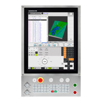
HEIDENHAIN TNC 620 User Manual (546 pages)
Brand:
HEIDENHAIN
| Category:
Control Panel
| Size: 7 MB
Table of Contents
Fundamentals | New Cycle Functions of Software 81760X
3
Fundamentals | New and Changed Cycle Functions of Software 81760X
4
New and Changed Cycle Functions of Software 81760X
11
The Character Set of the Fixed Cycle 225 Engraving was
12
The Character Set of the Fixed Cycle 225 Engraving was
13
Table of Contents
17
Fundamentals / Overviews
45
Using Fixed Cycles
49
Working with Fixed Cycles
50
Machine-Specific Cycles (Software Option19)
50
Defining a Cycle Using Soft Keys
51
Defining a Cycle Using the GOTO Function
51
Calling a Cycle
52
Program Defaults for Cycles
54
Overview
54
Entering GLOBAL DEF
54
Using GLOBAL DEF Information
55
Global Data Valid Everywhere
56
Global Data for Drilling Operations
56
Global Data for Milling Operations with Pocket Cycles 25X
56
Global Data for Milling Operations with Contour Cycles
56
Global Data for Positioning Behavior
57
Global Data for Probing Functions
57
PATTERN DEF Pattern Definition
58
Application
58
Entering PATTERN DEF
59
Using PATTERN DEF
59
Defining Individual Machining Positions
60
Defining a Single Row
60
Defining a Single Pattern
61
Defining Individual Frames
62
Defining a Full Circle
63
Defining a Pitch Circle
64
Point Tables
65
Application
65
Creating a Point Table
65
Hiding Single Points from the Machining Process
66
Selecting a Point Table in the Program
66
Calling a Cycle in Connection with Point Tables
67
Fixed Cycles: Drilling
69
Fundamentals
70
Overview
70
CENTERING (Cycle 240, DIN/ISO: G240, Software Option 19)
71
Cycle Run
71
Please Note While Programming
71
Cycle Parameters
72
DRILLING (Cycle 200)
73
Cycle Run
73
Please Note While Programming
73
Cycle Parameters
74
REAMING (Cycle 201, DIN/ISO: G201, Software Option 19)
75
Cycle Run
75
Please Note While Programming
75
Cycle Parameters
76
BORING (Cycle 202, DIN/ISO: G202, Software Option 19)
77
Cycle Run
77
Please Note While Programming
78
Cycle Parameters
79
UNIVERSAL DRILLING (Cycle 203, DIN/ISO: G203, Software Option 19)
80
Cycle Run
80
Please Note While Programming
83
Cycle Parameters
84
BACK BORING (Cycle 204, DIN/ISO: G204, Software Option 19)
86
Cycle Run
86
Please Note While Programming
87
Cycle Parameters
88
UNIVERSAL PECKING (Cycle 205, DIN/ISO: G205, Software Option 19)
90
Cycle Run
90
Please Note While Programming
91
Cycle Parameters
92
Position Behavior When Working with Q379
94
BORE MILLING (Cycle 208, Software Option 19)
98
Cycle Run
98
Please Note While Programming
99
Cycle Parameters
100
SINGLE-LIP DEEP-HOLE DRILLING (Cycle 241, DIN/ISO: G241, Software Option 19)
101
Cycle Run
101
Please Note While Programming
102
Cycle Parameters
103
Position Behavior When Working with Q379
105
3.11 Programming Examples
109
Example: Drilling Cycles
109
Example: Using Drilling Cycles in Connection with PATTERN DEF
110
Fixed Cycles: Tapping / Thread Milling
113
Fundamentals
114
Overview
114
TAPPING with a Floating Tap Holder (Cycle 206, DIN/ISO: G206)
115
Cycle Run
115
Please Note While Programming
116
Cycle Parameters
117
RIGID TAPPING Without a Floating Tap Holder (Cycle 207, DIN/ISO: G207)
118
Cycle Run
118
Please Note While Programming
119
Cycle Parameters
120
Retracting after a Program Interruption
121
TAPPING with CHIP BREAKING (Cycle 209, DIN/ISO: G209, Software Option 19)
122
Cycle Run
122
Please Note While Programming
123
Cycle Parameters
124
Fundamentals of Thread Milling
126
Prerequisites
126
THREAD MILLING (Cycle 262, DIN/ISO: G262, Software Option 19)
128
Cycle Run
128
Please Note While Programming
129
Cycle Parameters
130
THREAD MILLING/COUNTERSINKING (Cycle 263, DIN/ISO: G263, Software Option 19)
131
Cycle Run
131
Please Note While Programming
132
Cycle Parameters
133
THREAD DRILLING/MILLING (Cycle 264, DIN/ISO: G264, Software Option 19)
135
Cycle Run
135
Please Note While Programming
136
Cycle Parameters
137
HELICAL THREAD DRILLING/MILLING (Cycle 265, DIN/ISO: G265, Software Option 19)
139
Cycle Run
139
Please Note While Programming
140
Cycle Parameters
141
OUTSIDE THREAD MILLING (Cycle 267, DIN/ISO: G267, Software Option 19)
143
Cycle Run
143
Please Note While Programming
144
Cycle Parameters
145
4.11 Programming Examples
147
Example: Thread Milling
147
Fixed Cycles: Pocket Milling / Stud Milling / Slot Milling
149
Fundamentals
150
Overview
150
RECTANGULAR POCKET (Cycle 251, DIN/ISO: G251, Software Option 19)
151
Cycle Run
151
Please Note While Programming
152
Cycle Parameters
154
CIRCULAR POCKET (Cycle 252, DIN/ISO: G252, Software Option 19)
156
Cycle Run
156
Please Note While Programming
158
Cycle Parameters
160
SLOT MILLING (Cycle 253, DIN/ISO: G253), Software Option 19
162
Cycle Run
162
Please Note While Programming
163
Cycle Parameters
164
CIRCULAR SLOT (Cycle 254, DIN/ISO: G254, Software Option 19)
166
Cycle Run
166
Please Note While Programming
167
Cycle Parameters
169
RECTANGULAR STUD (Cycle 256, DIN/ISO: G256, Software Option 19)
172
Cycle Run
172
Please Note While Programming
173
Cycle Parameters
174
CIRCULAR STUD (Cycle 257, DIN/ISO: G257, Software Option 19)
177
Cycle Run
177
Please Note While Programming
178
Cycle Parameters
179
POLYGON STUD (Cycle 258, DIN/ISO: G258, Software Option 19)
181
Cycle Run
181
Please Note While Programming
182
Cycle Parameters
184
FACE MILLING (Cycle 233, DIN/ISO: G233, Software Option 19)
186
Cycle Run
186
Please Note While Programming
190
Cycle Parameters
191
Programming Examples
194
Example: Milling Pockets, Studs and Slots
194
Fixed Cycles: Pattern Definitions
197
Fundamentals
198
Overview
198
POLAR PATTERN (Cycle 220, DIN/ISO: G220, Software Option 19)
199
Cycle Run
199
Please Note While Programming
199
Cycle Parameters
200
LINEAR PATTERN (Cycle 221, DIN/ISO: G221, Software Option 19)
202
Cycle Run
202
Please Note While Programming
202
Cycle Parameters
203
Programming Examples
204
Example: Polar Hole Patterns
204
Fixed Cycles: Contour Pocket
207
SL Cycles
208
Fundamentals
208
Overview
210
CONTOUR (Cycle 14, DIN/ISO: G37)
211
Please Note While Programming
211
Cycle Parameters
211
Superimposed Contours
212
Fundamentals
212
Subprograms: Overlapping Pockets
212
Area of Inclusion
213
Area of Exclusion
214
Area of Intersection
215
CONTOUR DATA (Cycle 20, DIN/ISO: G120, Software Option 19)
216
Please Note While Programming
216
Cycle Parameters
217
PILOT DRILLING (Cycle 21, DIN/ISO: G121, Software Option 19)
218
Cycle Run
218
Please Note While Programming
219
Cycle Parameters
219
ROUGHING (Cycle 22, DIN/ISO: G122, Software Option 19)
220
Cycle Run
220
Please Note While Programming
221
Cycle Parameters
222
FLOOR FINISHING (Cycle 23, DIN/ISO: G123, Software Option 19)
224
Cycle Run
224
Please Note While Programming
225
Cycle Parameters
225
SIDE FINISHING (Cycle 24, DIN/ISO: G124, Software Option 19)
226
Cycle Run
226
Please Note While Programming
227
Cycle Parameters
228
CONTOUR TRAIN (Cycle 25, DIN/ISO: G125, Software Option 19)
229
Cycle Run
229
Please Note While Programming
230
Cycle Parameters
231
THREE-D CONT. TRAIN (Cycle 276, DIN/ISO: G276, Software Option 19)
233
Cycle Run
233
Please Note While Programming
234
Cycle Parameters
236
CONTOUR TRAIN DATA (Cycle 270, DIN/ISO: G270, Software Option 19)
238
Please Note While Programming
238
Cycle Parameters
239
TROCHOIDAL SLOT (Cycle 275, DIN/ISO: G275, Software Option 19)
240
Cycle Run
240
Please Note While Programming
242
Cycle Parameters
243
Programming Examples
245
Example: Roughing-Out and Fine-Roughing a Pocket
245
Example: Pilot Drilling, Roughing-Out and Finishing Overlapping Contours
247
Example: Contour Train
249
Advertisement
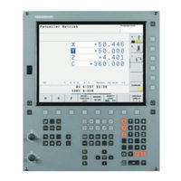
HEIDENHAIN TNC 620 User Manual (616 pages)
Brand:
HEIDENHAIN
| Category:
Control Systems
| Size: 16 MB
Table of Contents
Table of Contents
19
TNC 620 | User's Manual HEIDENHAIN Conversational Programming | 3/2014
41
1 First Steps with the TNC 620
47
Overview
48
Machine Switch-On
48
Acknowledging the Power Interruption and Moving to the Reference Points
48
Programming the First Part
49
Selecting the Correct Operating Mode
49
The most Important TNC Keys
49
Creating a New Program/File Management
50
Defining a Workpiece Blank
51
Program Layout
52
Programming a Simple Contour
53
Creating a Cycle Program
56
Graphically Testing the First Part (Advanced Graphic Features Software Option)
58
Selecting the Correct Operating Mode
58
Selecting the Tool Table for the Test Run
58
Choosing the Program You Want to Test
59
Selecting the Screen Layout and the View
59
Starting the Test Run
60
Setting up Tools
61
Selecting the Correct Operating Mode
61
Preparing and Measuring Tools
61
The Tool Table TOOL.T
62
The Pocket Table TOOL_P .TCH
63
Workpiece Setup
64
Selecting the Correct Operating Mode
64
Clamping the Workpiece
64
Datum Setting with 3-D Touch Probe (Software Option: Touch Probe Function)
65
Running the First Program
66
Selecting the Correct Operating Mode
66
Choosing the Program You Want to Run
66
Start the Program
66
2 Introduction
67
The TNC 620
68
Programming: HEIDENHAIN Conversational and ISO Formats
68
Compatibility
68
Visual Display Unit and Operating Panel
69
Display Screen
69
Setting the Screen Layout
70
Control Panel
70
Modes of Operation
71
Manual Operation and El. Handwheel
71
Positioning with Manual Data Input
71
Programming
71
Test Run
72
Program Run, Full Sequence and Program Run, Single Block
72
Status Displays
73
General" Status Display
73
Additional Status Displays
74
Window Manager
80
Task Bar
81
Selinux Security Software
82
Accessories: HEIDENHAIN 3-D Touch Probes and Electronic Handwheels
83
3-D Touch Probes (Touch Probe Function Software Option)
83
HR Electronic Handwheels
84
3 Programming: Fundamentals, File Management
85
Fundamentals
86
Reference System on Milling Machines
87
Polar Coordinates
88
Absolute and Incremental Workpiece Positions
89
Selecting the Datum
90
Opening Programs and Entering
91
Define the Blank: BLK FORM
92
Opening a New Part Program
94
Programming Tool Movements in Conversational
95
Actual Position Capture
97
Editing a Program
98
The TNC Search Function
101
File Manager: Fundamentals
103
Displaying Externally Generated Files on the TNC
105
Working with the File Manager
106
Directories
106
Paths
106
Overview: Functions of the File Manager
107
Calling the File Manager
108
Selecting Drives, Directories and Files
109
Creating a New Directory
110
Creating a New File
110
Copying a Single File
110
Copying Files into Another Directory
111
Copying a Table
112
Copying a Directory
112
Choosing One of the Last Files Selected
113
Deleting a File
114
Deleting a Directory
114
Tagging Files
115
Renaming a File
116
Sorting Files
116
Additional Functions
117
Additional Tools for Management of External File Types
118
Data Transfer To/From an External Data Medium
123
The TNC in a Network
125
USB Devices on the TNC
126
4 Programming: Programming Aids
129
Screen Keyboard
130
Adding Comments
131
Functions for Editing of the Comment
132
Display of NC Programs
133
Structuring Programs
134
Calculator
135
Cutting Data Calculator
138
Programming Graphics
141
Block Number Display ON/OFF
142
Magnification or Reduction of Details
143
Error Messages
144
Display of Errors
144
Open the Error Window
144
Closing the Error Window
144
Detailed Error Messages
145
INTERNAL INFO Soft Key
145
Clearing Errors
146
Error Log
146
Keystroke Log
147
Informational Texts
148
Saving Service Files
148
Calling the Tncguide Help System
149
Tncguide Context-Sensitive Help System
150
Application
150
Working with the Tncguide
151
Downloading Current Help Files
155
5 Programming: Tools
157
Entering Tool-Related Data
158
Spindle Speed S
159
Tool Data
160
Delta Values for Lengths and Radii
161
Enter Tool Data into the Table
162
Importing Tool Tables
170
Pocket Table for Tool Changer
171
Call Tool Data
174
Tool Change
176
Tool Usage Test
179
Tool Compensation
181
Tool Radius Compensation
182
6 Programming: Programming Contours
185
Tool Movements
186
Path Functions
186
FK Free Contour Programming (Advanced Programming Features Software Option)
186
Miscellaneous Functions M
186
Subprograms and Program Section Repeats
187
Programming with Q Parameters
187
Fundamentals of Path Functions
188
Programming Tool Movements for Workpiece Machining
188
Approaching and Departing a Contour
192
Overview: Types of Paths for Contour Approach and Departure
192
Important Positions for Approach and Departure
193
Approaching on a Straight Line with Tangential Connection: APPR LT
195
Approaching on a Straight Line Perpendicular to the First Contour Point: APPR LN
195
Approaching on a Circular Path with Tangential Connection: APPR CT
196
Approaching on a Circular Path with Tangential Connection from a Straight Line to the Contour: APPR LCT
197
Departing in a Straight Line with Tangential Connection: DEP LT
197
Departing in a Straight Line Perpendicular to the Last Contour Point: DEP LN
198
Departing on a Circular Path with Tangential Connection: DEP CT
199
Departing on a Circular Arc Tangentially Connecting the Contour and a Straight Line: DEP LCT
199
Path Contours - Cartesian Coordinates
200
Overview of Path Functions
200
Straight Line L
201
Inserting a Chamfer between Two Straight Lines
202
Corner Rounding RND
203
Circle Center CC
204
Circular Path C Around Circle Center CC
205
Circlecr with Defined Radius
206
Circle CT with Tangential Connection
208
Example: Linear Movements and Chamfers with Cartesian Coordinates
209
Example: Circular Movements with Cartesian Coordinates
210
Example: Full Circle with Cartesian Coordinates
211
Path Contours – Polar Coordinates
212
Zero Point for Polar Coordinates: Pole CC
213
Circular Path CP Around Pole CC
214
Helix
215
Example: Linear Movement with Polar Coordinates
217
Example: Helix
218
Path Contours – FK Free Contour Programming (Advanced Programming Features Software Option)
219
FK Programming Graphics
221
Initiating the FK Dialog
223
Free Straight Line Programming
224
Free Circular Path Programming
225
Input Options
226
Auxiliary Points
229
Relative Data
230
Example: FK Programming 1
232
Example: FK Programming 2
233
Example: FK Programming 3
234
HEIDENHAIN TNC 620 User Manual (598 pages)
Klartext Programming
Brand:
HEIDENHAIN
| Category:
Control Systems
| Size: 11 MB
Table of Contents
Table of Contents
7
Basic Information
31
About this Manual
32
Control Model, Software and Features
34
Software Options
36
New Functions 81760X-16
40
First Steps
49
Overview
50
Switching on the Machine
51
Acknowledging the Power Interruption
51
Programming the First Part
52
Selecting the Operating Mode
52
Important Controls and Displays
52
Creating a New NC Program / File Management
53
Defining a Workpiece Blank
54
Program Layout
55
Programming a Simple Contour
56
Creating a Cycle Program
61
Fundamentals
65
The TNC 620
66
HEIDENHAIN Klartext and ISO
66
Compatibility
66
Visual Display Unit and Operating Panel
67
Display Screen
67
Setting the Screen Layout
68
Operating Panel
69
Screen Keypad
72
Modes of Operation
73
Manual Operation and El. Handwheel
73
Positioning with Manual Data Input
73
Programming
74
Test Run
74
Program Run, Full Sequence and Program Run, Single Block
75
NC Fundamentals
76
Position Encoders and Reference Marks
76
Programmable Axes
76
Reference Systems
77
Designation of the Axes on Milling Machines
87
Polar Coordinates
87
Absolute and Incremental Workpiece Positions
88
Selecting the Preset
89
Creating and Entering NC Programs
90
Structure of an NC Program in HEIDENHAIN Klartext
90
Defining the Workpiece Blank: BLK FORM
91
Creating a New NC Program
94
Programming Tool Movements in Klartext
96
Actual Position Capture
98
Editing an NC Program
99
The Control's Search Function
103
File Management
105
Files
105
Displaying Externally Generated Files on the Control
107
Directories
107
Paths
107
Overview: Functions of the File Manager
108
Calling the File Manager
109
Selecting Drives, Directories and Files
110
Creating a New Directory
112
Creating New File
112
Copying a Single File
112
Copying Files into Another Directory
113
Copying a Table
114
Copying a Directory
115
Choosing One of the Last Files Selected
115
Deleting a File
116
Deleting a Directory
116
Tagging Files
117
Renaming a File
118
Sorting Files
118
Additional Functions
119
Tools
121
Entering Tool-Related Data
122
Feed Rate F
122
Spindle Speed S
123
Tool Data
124
Requirements for Tool Compensation
124
Tool Number, Tool Name
124
Tool Length L
124
Tool Radius R
126
Delta Values for Lengths and Radii
126
Entering Tool Data into the NC Program
127
Calling the Tool Data
128
Tool Change
130
Tool Compensation
133
Introduction
133
Tool Length Compensation
133
Tool Radius Compensation
134
Programming Contours
137
Tool Movements
138
Path Functions
138
FK Free Contour Programming (Option 19)
138
Miscellaneous Functions M
138
Subprograms and Program Section Repeats
139
Programming with Q Parameters
139
Fundamentals of Path Functions
140
Programming Tool Movements for Machining
140
Approaching and Departing a Contour
144
Starting Point and End Point
144
Overview: Types of Paths for Contour Approach and Departure
146
Important Positions for Approach and Departure
147
Approaching on a Straight Line with Tangential Connection: APPR LT
149
Approaching on a Straight Line Perpendicular to the First Contour Point: APPR LN
149
Approaching on a Circular Path with Tangential Connection: APPR CT
150
Approaching on a Circular Path with Tangential Connection from a Straight Line to the Contour: APPR LCT
151
Departing in a Straight Line with Tangential Connection: DEP LT
152
Departing in a Straight Line Perpendicular to the Last Contour Point: DEP LN
152
Departing on a Circular Path with Tangential Connection: DEP CT
153
Departing on a Circular Arc Tangentially Connecting the Contour and a Straight Line: DEP LCT
153
Path Contours - Cartesian Coordinates
154
Overview of Path Functions
154
Straight Line L
155
Inserting a Chamfer between Two Straight Lines
156
Rounded Corners RND
157
Circle Center CC
158
Circular Arc C Around Circle Center CC
159
Circular Arc CR with Fixed Radius
161
Circular Arc CT with Tangential Transition
163
Superimposing a Linear Motion on a Circular Contour
164
Example: Linear Movements and Chamfers with Cartesian Coordinates
165
Example: Circular Movements with Cartesian Coordinates
166
Example: Full Circle with Cartesian Coordinates
167
Path Contours - Polar Coordinates
168
Overview
168
Datum for Polar Coordinates: Pole CC
169
Straight Line LP
169
Circular Path CP Around Pole CC
170
Circle CTP with Tangential Connection
170
Helix
171
Example: Linear Movement with Polar Coordinates
173
Example: Helix
174
Path Contours - FK Free Contour Programming (Option 19)
175
Fundamentals
175
Defining the Working Plane
176
FK Programming Graphics
177
Initiating the FK Dialog
178
Pole for FK Programming
178
Free Straight Line Programming
179
Free Circular Path Programming
180
Input Possibilities
181
Auxiliary Points
184
Relative Data
185
Example: FK Programming 1
187
Example: FK Programming 2
188
Example: FK Programming 3
189
Programming Aids
191
GOTO Function
192
Using the GOTO Key
192
Screen Keypad
193
Entering Text with the Screen Keypad
193
Display of NC Programs
194
Syntax Highlighting
194
Scrollbar
194
Adding Comments
195
Application
195
Entering Comments During Programming
195
Inserting Comments after Program Entry
195
Entering a Comment in a Separate NC Block
195
Commenting out an Existing NC Block
195
Functions for Editing a Comment
196
Freely Editing an NC Program
197
Skipping NC Blocks
198
Insert a Slash (/)
198
Delete the Slash (/)
198
Structuring NC Programs
199
Definition and Applications
199
Displaying the Program Structure Window / Changing the Active Window
199
Inserting a Structure Block in the Program Window
200
Selecting Blocks in the Program Structure Window
200
Calculator
201
Operation
201
Cutting Data Calculator
203
Application
203
Working with Cutting Data Tables
204
6.10 Programming Graphics
207
Activating and Deactivating Programming Graphics
207
Generating a Graphic for an Existing NC Program
208
Block Number Display ON/OFF
208
Erasing the Graphic
208
Showing Grid Lines
208
Magnification or Reduction of Details
209
6.11 Error Messages
210
Display of Errors
210
Opening the Error Window
210
Detailed Error Messages
211
INTERNAL INFO Soft Key
211
Advertisement
HEIDENHAIN TNC 620 User Manual (539 pages)
Brand:
HEIDENHAIN
| Category:
Industrial Equipment
| Size: 11 MB
Table of Contents
Software Options
6
Legal Information
8
Table of Contents
9
Introduction
29
Visual Display Unit
31
Sets the Screen Layout
32
Operating Panel
33
Operating Modes
34
Manual Operation and Electronic Handwheel
34
Positioning with Manual Data Input
34
Programming and Editing
35
Program Run, Full Sequence and Program Run, Single Block
36
"General" Status Display
37
Additional Status Displays
39
D Touch Probes
42
HR Electronic Handwheels
43
Manual Operation and Setup
45
Switch-On, Switch-Off
46
To Traverse with the Machine Axis Direction Buttons
49
Incremental Jog Positioning
50
Traversing with the HR 410 Electronic Handwheel
51
Entering Values
52
Changing the Spindle Speed and Feed Rate
53
Datum Setting (Without a 3-D Touch Probe)
54
Datum Management with the Preset Table
56
Tilting the Working Plane (Software Option 1)
62
Application, Function
62
Traversing the Reference Points in Tilted Axes
64
Position Display in a Tilted System
64
Limitations on Working with the Tilting Function
64
Activating Manual Tilting
65
Positioning with Manual Data Input
67
Programming and Executing Simple Machining Operations
68
Protecting and Erasing Programs in $MDI
71
Programming: Fundamentals of File
73
Management, Programming Aids
73
Position Encoders and Reference Marks
74
Reference System
74
Reference System on Milling Machines
75
Designation of the Axes on Milling Machines
75
Polar Coordinates
76
Absolute and Incremental Workpiece Positions
77
Setting the Datum
78
Screen Keypad
81
Data Backup
81
Working with the File Manager
82
Overview: Functions of the File Manager
83
Calling the File Manager
84
Selecting Drives, Directories and Files
85
Creating a New Directory
86
Copying a Single File
87
Copying a Directory
87
Choosing One of the Last 10 Files Selected
88
Deleting a File
88
Deleting a Directory
88
Marking Files
89
Renaming a File
90
File Sorting
90
Data Transfer to or from an External Data Medium
91
Copying Files into Another Directory
93
The TNC in a Network
94
Creating and Writing Programs
96
Organization of an NC Program in HEIDENHAIN Conversational Format
96
Creating a New Part Program
97
Programming Tool Movements in Conversational Format
99
Actual Position Capture
100
Editing a Program
101
The TNC Search Function
105
Generating / Not Generating Graphics During Programming
107
Generating a Graphic for an Existing Program
107
Block Number Display ON/OFF
108
Erasing the Graphic
108
Magnifying or Reducing a Detail
108
Structuring Programs
109
Adding Comments
110
Functions for Editing of the Comment
110
Integrated Pocket Calculator
111
Operation
111
Error Messages
113
Display of Errors
113
Detailed Error Messages
114
INTERNAL INFO Soft Key
114
Clearing Errors
115
Error Log
115
Keystroke Log
116
Informational Texts
117
Saving Service Files
117
Programming: Tools
119
Entering Tool-Related Data
120
Feed Rate F
120
Spindle Speed S
121
Requirements for Tool Compensation
122
Tool Numbers and Tool Names
122
Tool Length L
122
Tool Radius R
123
Delta Values for Lengths and Radii
123
Entering Tool Data into the Program
123
Entering Tool Data in the Table
124
Pocket Table for Tool Changer
130
Calling Tool Data
133
Tool Length Compensation
134
Tool Radius Compensation
135
Definition of a Normalized Vector
139
Permissible Tool Forms
140
Using Other Tools: Delta Values
140
Face Milling: 3-D Compensation with and Without Tool Orientation
141
Peripheral Milling: 3-D Radius Compensation with Workpiece Orientation
142
Programming: Programming Contours
145
Tool Movements
146
HEIDENHAIN TNC 620 User Manual (499 pages)
Setup, Testing and Running NC Programs
Brand:
HEIDENHAIN
| Category:
Control Panel
| Size: 12 MB
Table of Contents
Table of Contents
5
Fundamentals
25
About this Manual
26
Control Model, Software and Features
28
Software Options
29
New Functions 81760X-05
33
New Functions 81760X-06
37
First Steps
41
Overview
42
Switching on the Machine
43
Acknowledging the Power Interruption and Moving to the Reference Points
43
Graphically Testing the Workpiece (Option 20)
44
Selecting the Test Run Operating Mode
44
Selecting the Tool Table
44
Selecting the NC Program
45
Selecting the Screen Layout and the View
45
Starting the Test Run
46
Setting up Tools
47
Selecting the Manual Operation Mode
47
Preparing and Measuring Tools
47
Editing the TOOL.T Tool Table
48
Editing the TOOL_P .TCH Pocket Table
49
Workpiece Setup
50
Selecting the Correct Operating Mode
50
Clamping the Workpiece
50
Presetting with a 3-D Touch Probe (Option Number 17)
51
Machining the Workpiece
52
Selecting the Program Run, Single Block or Program Run, Full Sequence Operating Mode
52
Selecting the NC Program
52
Starting an NC Program
52
Fundamentals
53
The TNC 620
54
HEIDENHAIN Klartext and DIN/ISO
54
Compatibility
54
Data Security and Data Protection
55
Visual Display Unit and Operating Panel
57
Display Screen
57
Setting the Screen Layout
58
Control Panel
59
Screen Keypad
59
Modes of Operation
61
Manual Operation and El. Handwheel
61
Positioning with Manual Data Input
61
Programming
62
Test Run
62
Program Run, Full Sequence and Program Run, Single Block
63
Status Displays
64
General Status Display
64
Additional Status Displays
66
File Management
73
Files
73
Displaying Externally Generated Files on the Control
75
Directories
75
Paths
75
Calling the File Manager
76
Additional Functions
77
Selecting Drives, Directories and Files
78
Choosing One of the Last Files Selected
80
USB Devices on the Control
81
Data Transfer to or from an External Data Carrier
82
The Control in a Network
83
Data Backup
85
Importing a File from an Itnc 530
85
Additional Tools for Management of External File Types
86
Error Messages and Help System
95
Error Messages
95
Tncguide Context-Sensitive Help System
100
NC Fundamentals
106
Position Encoders and Reference Marks
106
Programmable Axes
107
Reference Systems
108
Accessories: HEIDENHAIN 3-D Touch Probes and Electronic Handwheels
118
HR Electronic Handwheels
119
Tools
121
Tool Data
122
Tool Table Fundamentals
123
Entering Tool Data into the Table
127
Importing Tool Tables
132
Overwriting Tool Data from an External PC
134
Pocket Table for Tool Changer
135
Tool Change
138
Tool Usage Test
139
Tool Management
142
Calling Tool Management
143
Editing Tool Management
144
Available Tool Types
148
Importing and Exporting Tool Data
149
Tool Carrier Management
152
Assigning Input Parameters to Tool Carriers
153
Allocating Parameterized Tool Carriers
156
HEIDENHAIN TNC 620 User Manual (521 pages)
Setup, Testing and Running NC Programs
Brand:
HEIDENHAIN
| Category:
Control Systems
| Size: 14 MB
Table of Contents
Table of Contents
5
Basic Information
25
About this Manual
26
Control Model, Software and Features
28
Software Options
30
New Functions 81760X-16
34
First Steps
43
Overview
44
Switching on the Machine
45
Acknowledging the Power Interruption and Moving to the Reference Points
45
Graphically Testing the Workpiece (Option 20)
46
Selecting the Test Run Operating Mode
46
Selecting the Tool Table
46
Selecting the NC Program
47
Selecting the Screen Layout and the View
47
Starting the Test Run
48
Setting up Tools
49
Selecting the Manual Operation Mode
49
Preparing and Measuring Tools
49
Editing the TOOL.T Tool Table
50
Editing the TOOL_P.TCH Pocket Table
51
Workpiece Setup
52
Selecting the Correct Operating Mode
52
Clamping the Workpiece
52
Presetting with a 3-D Touch Probe (Option Number 17)
52
Machining the Workpiece
54
Selecting the Program Run, Single Block or Program Run, Full Sequence Operating Mode
54
Selecting the NC Program
54
Starting an NC Program
54
Fundamentals
55
The TNC 620
56
HEIDENHAIN Klartext and ISO
56
Compatibility
56
Data Security and Data Protection
57
Visual Display Unit and Operating Panel
59
Display Screen
59
Setting the Screen Layout
60
Operating Panel
61
Screen Keypad
64
Modes of Operation
65
Manual Operation and El. Handwheel
65
Positioning with Manual Data Input
65
Programming
66
Test Run
66
Program Run, Full Sequence and Program Run, Single Block
67
Status Displays
68
General Status Display
68
Additional Status Displays
71
File Management
80
Files
80
Displaying Externally Generated Files on the Control
82
Directories
82
Paths
82
Calling the File Manager
83
Additional Functions
84
Selecting Drives, Directories and Files
86
Choosing One of the Last Files Selected
88
USB Devices on the Control
88
Data Transfer to or from an External Data Carrier
90
The Control Within the Network
91
Data Backup
92
Importing a File from an Itnc 530
92
Additional Tools for Management of External File Types
93
Error Messages and Help System
101
Error Messages
101
Tncguide: Context-Sensitive Help
107
NC Fundamentals
113
Position Encoders and Reference Marks
113
Programmable Axes
113
Reference Systems
114
Accessories: HEIDENHAIN 3-D Touch Probes and Electronic Handwheels
124
3-D Touch Probes (Option 17)
124
HR Electronic Handwheels
125
Tools
127
Tool Data
128
Tool Number, Tool Name
128
Tool Length L
128
Tool Radius R
130
Tool Table Fundamentals
130
Creating and Activating an INCH-Based Tool Table
134
Entering Tool Data into the Table
135
HEIDENHAIN TNC 620 Operating Instructions Manual (64 pages)
Programming Station
Brand:
HEIDENHAIN
| Category:
Controller
| Size: 3 MB
Table of Contents
Table of Contents
7
1 Important Information on the Software for the Programming Station
9
1.1 Introduction
10
General Information
10
Options/Feature Content Level (FCL)
10
1.2 Compatibility
11
Downward Compatibility
12
Differences in Fixed Cycles
13
Differences in Touch Probe Cycles
19
Differences in Miscellaneous Functions M
27
Differences in Q-Parameter Programming
31
Differences in Other Functions
33
Working with the Programming Station
36
Starting the Programming Station
36
Showing the Virtual Keyboard
37
Exiting the Programming Station
37
Data Transfer from the Programming Station to the Machine Tool
39
Prerequisites
39
Preparations at the Programming Station
39
Calling a Program from the Machine Tool
40
Connection between the Programming Station and HEIDENHAIN PC Software
40
Special Features of the Demo Version
41
General Information
41
Starting the Demo Version
41
Keyboard Assignment
42
Overview of Keyboard Assignment
46
Key Assignment on Portable Computers
47
2 Items Supplied / Installation
49
Items Supplied / System Requirements
50
Items Supplied
50
System Requirements
51
Connecting the Programming Station
52
Connecting the Keyboard for the Programming Station
52
Mounting the Cable Clamps for the USB Cable
52
Number Stickers
53
Connecting the USB Dongle (for the Version with a Virtual Keyboard)
53
Connecting the USB Network Dongle (Only for the Version with a Virtual Keyboard)
53
Installing the Programming Station Software
54
Configuring the Programming Station Software for Use with a USB Network Dongle
55
Network License for Multiple Workstations
56
Setting the Conversational Language
58
Working with the HEIDENHAIN Basic PLC Program
60
Working with a Machine-Specific PLC Program
61
Displaying Additional Drives
61
HEIDENHAIN TNC 620 Replacing Instructions (12 pages)
Brand:
HEIDENHAIN
| Category:
Control Systems
| Size: 0 MB
Advertisement
Related Products
Heidenhain TNC 640 5E
HEIDENHAIN TNC 620 Programming Station
HEIDENHAIN TNC 620 E
HEIDENHAIN TNC 640
HEIDENHAIN TNC 640 E
HEIDENHAIN TNC 320 Programming Station
HEIDENHAIN TNC 151 F
HEIDENHAIN TNC 151 W
HEIDENHAIN TNC 426 PB/M
HEIDENHAIN TNC 426
HEIDENHAIN Categories
Media Converter
Measuring Instruments
Industrial Equipment
Control Systems
Scanner
More HEIDENHAIN Manuals
Login
Sign In
OR
Sign in with Facebook
Sign in with Google
Upload manual
Upload from disk
Upload from URL