Sign In
Upload
Manuals
Brands
HEIDENHAIN Manuals
Control Unit
TNC 320 Programming Station
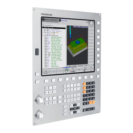
HEIDENHAIN TNC 320 Programming Station Manuals
Manuals and User Guides for HEIDENHAIN TNC 320 Programming Station. We have
3
HEIDENHAIN TNC 320 Programming Station manuals available for free PDF download: User Manual, User's Manual For Cycle Programming
HEIDENHAIN TNC 320 Programming Station User's Manual For Cycle Programming (465 pages)
Brand:
HEIDENHAIN
| Category:
Control Unit
| Size: 8 MB
Table of Contents
The Character Set of the Fixed Cycle 225 Engraving was
10
New and Changed Cycle Functions of Software 77185X
11
Table of Contents
13
Fundamentals / Overviews
41
Using Fixed Cycles
45
Working with Fixed Cycles
46
Machine-Specific Cycles
46
Defining a Cycle Using Soft Keys
47
Defining a Cycle Using the GOTO Function
47
Calling a Cycle
48
Program Defaults for Cycles
50
Overview
50
Entering GLOBAL DEF
50
Using GLOBAL DEF Information
51
Global Data Valid Everywhere
51
Global Data for Drilling Operations
52
Global Data for Milling Operations with Pocket Cycles 25X
52
Global Data for Milling Operations with Contour Cycles
52
Global Data for Positioning Behavior
53
Global Data for Probing Functions
53
PATTERN DEF Pattern Definition
54
Application
54
Entering PATTERN DEF
54
Using PATTERN DEF
55
Defining Individual Machining Positions
55
Defining a Single Row
56
Defining a Single Pattern
57
Defining Individual Frames
58
Defining a Full Circle
59
Defining a Pitch Circle
59
Point Tables
60
Application
60
Creating a Point Table
60
Hiding Single Points from the Machining Process
61
Selecting a Point Table in the Program
61
Calling a Cycle in Connection with Point Tables
62
Fixed Cycles: Drilling
63
Fundamentals
64
Overview
64
CENTERING (Cycle 240, DIN/ISO: G240)
65
Cycle Run
65
Please Note While Programming
65
Cycle Parameters
66
DRILLING (Cycle 200)
67
Cycle Run
67
Please Note While Programming
67
Cycle Parameters
68
REAMING (Cycle 201, DIN/ISO: G201)
69
Cycle Run
69
Please Note While Programming
69
Cycle Parameters
70
BORING (Cycle 202, DIN/ISO: G202)
71
Cycle Run
71
Please Note While Programming
72
Cycle Parameters
73
UNIVERSAL DRILLING (Cycle 203, DIN/ISO: G203)
74
Cycle Run
74
Please Note While Programming
74
Cycle Parameters
75
BACK BORING (Cycle 204, DIN/ISO: G204)
77
Cycle Run
77
Please Note While Programming
78
Cycle Parameters
79
UNIVERSAL PECKING (Cycle 205, DIN/ISO: G205)
81
Cycle Run
81
Please Note While Programming
82
Cycle Parameters
83
BORE MILLING (Cycle 208)
85
Cycle Run
85
Please Note While Programming
85
Cycle Parameters
86
SINGLE-LIP DEEP-HOLE DRILLING (Cycle 241, DIN/ISO: G241) 3.10
87
Cycle Run
87
Please Note While Programming
87
Cycle Parameters
88
3.11 Programming Examples
90
Example: Drilling Cycles
90
Example: Using Drilling Cycles in Connection with PATTERN DEF
91
Fixed Cycles: Tapping / Thread Milling
93
Fundamentals
94
Overview
94
TAPPING with a Floating Tap Holder (Cycle 206, DIN/ISO: G206)
95
Cycle Run
95
Please Note While Programming
95
Cycle Parameters
96
RIGID TAPPING Without a Floating Tap Holder (Cycle 207, DIN/ISO: G207)
97
Cycle Run
97
Please Note While Programming
98
Cycle Parameters
99
Retracting after a Program Interruption
99
TAPPING with CHIP BREAKING (Cycle 209, DIN/ISO: G209)
100
Cycle Run
100
Please Note While Programming
101
Cycle Parameters
102
Fundamentals of Thread Milling
104
Prerequisites
104
THREAD MILLING (Cycle 262, DIN/ISO: G262)
106
Cycle Run
106
Please Note While Programming
107
Cycle Parameters
108
THREAD MILLING/COUNTERSINKING (Cycle 263, DIN/ISO: G263)
110
Cycle Run
110
Please Note While Programming
111
Cycle Parameters
112
THREAD DRILLING/MILLING (Cycle 264, DIN/ISO: G264)
114
Cycle Run
114
Please Note While Programming
115
Cycle Parameters
116
HELICAL THREAD DRILLING/MILLING (Cycle 265, DIN/ISO: G265)
118
Cycle Run
118
Please Note While Programming
119
Cycle Parameters
120
OUTSIDE THREAD MILLING (Cycle 267, DIN/ISO: G267)
122
Cycle Run
122
Please Note While Programming
123
Cycle Parameters
124
4.11 Programming Examples
126
Example: Thread Milling
126
Fixed Cycles: Pocket Milling / Stud Milling / Slot Milling
129
Fundamentals
130
Overview
130
RECTANGULAR POCKET (Cycle 251, DIN/ISO: G251)
131
Cycle Run
131
Please Note While Programming
132
Cycle Parameters
133
CIRCULAR POCKET (Cycle 252, DIN/ISO: G252)
136
Cycle Run
136
Please Note While Programming
138
Cycle Parameters
139
SLOT MILLING (Cycle 253, DIN/ISO: G253)
141
Cycle Run
141
Please Note While Programming
142
Cycle Parameters
143
CIRCULAR SLOT (Cycle 254, DIN/ISO: G254)
146
Cycle Run
146
Please Note While Programming
147
Cycle Parameters
148
RECTANGULAR STUD (Cycle 256, DIN/ISO: G256)
151
Cycle Run
151
Please Note While Programming
152
Cycle Parameters
153
CIRCULAR STUD (Cycle 257, DIN/ISO: G257)
155
Cycle Run
155
Please Note While Programming
156
Cycle Parameters
157
POLYGON STUD (Cycle 258, DIN/ISO: G258)
159
Cycle Run
159
Please Note While Programming
160
Cycle Parameters
161
FACE MILLING (Cycle 233, DIN/ISO: G233)
164
Cycle Run
164
Please Note While Programming
167
Cycle Parameters
168
Programming Examples
171
Example: Milling Pockets, Studs and Slots
171
Fixed Cycles: Pattern Definitions
175
Fundamentals
176
Overview
176
POLAR PATTERN (Cycle 220, DIN/ISO: G220)
177
Cycle Run
177
Please Note While Programming
177
Cycle Parameters
178
LINEAR PATTERN (Cycle 221, DIN/ISO: G221)
180
Cycle Run
180
Please Note While Programming
180
Cycle Parameters
181
Programming Examples
182
Example: Polar Hole Patterns
182
Fixed Cycles: Contour Pocket
185
SL Cycles
186
Fundamentals
186
Overview
187
CONTOUR (Cycle 14, DIN/ISO: G37)
188
Please Note While Programming
188
Cycle Parameters
188
Superimposed Contours
189
Fundamentals
189
Subprograms: Overlapping Pockets
189
Area of Inclusion
190
Area of Exclusion
190
Area of Intersection
191
CONTOUR DATA (Cycle 20, DIN/ISO: G120)
192
Please Note While Programming
192
Cycle Parameters
193
PILOT DRILLING (Cycle 21, DIN/ISO: G121)
194
Cycle Run
194
Please Note While Programming
195
Cycle Parameters
195
ROUGHING (Cycle 22, DIN/ISO: G122)
196
Cycle Run
196
Please Note While Programming
197
Cycle Parameters
198
FLOOR FINISHING (Cycle 23, DIN/ISO: G123)
200
Cycle Run
200
Please Note While Programming
200
Cycle Parameters
201
SIDE FINISHING (Cycle 24, DIN/ISO: G124)
202
Cycle Run
202
Please Note While Programming
203
Cycle Parameters
204
CONTOUR TRAIN (Cycle 25, DIN/ISO: G125)
205
Cycle Run
205
Please Note While Programming
205
Cycle Parameters
206
CONTOUR TRAIN DATA (Cycle 270, DIN/ISO: G270)
207
Please Note While Programming
207
Cycle Parameters
207
TROCHOIDAL SLOT (Cycle 275, DIN/ISO: G275)
208
Cycle Run
208
Please Note While Programming
209
Cycle Parameters
210
Programming Examples
212
Example: Roughing-Out and Fine-Roughing a Pocket
212
Example: Pilot Drilling, Roughing-Out and Finishing Overlapping Contours
214
Example: Contour Train
216
Fixed Cycles: Cylindrical Surface
217
Fundamentals
218
Overview of Cylindrical Surface Cycles
218
CYLINDER SURFACE (Cycle 27, DIN/ISO: G127, Software Option 1)
219
Cycle Run
219
Please Note While Programming
220
Cycle Parameters
221
CYLINDER SURFACE Slot Milling (Cycle 28, DIN/ISO: G128, Software Option 1)
222
Cycle Run
222
Please Note While Programming
223
Cycle Parameters
224
CYLINDER SURFACE Ridge Milling (Cycle 29, DIN/ISO: G129, Software Option 1)
225
Cycle Run
225
Please Note While Programming
226
Cycle Parameters
227
CYLINDER SURFACE (Cycle 39, DIN/ISO: G139, Software Option 1)
228
Cycle Run
228
Please Note While Programming
229
Cycle Parameters
230
Programming Examples
231
Example: Cylinder Surface with Cycle 27
231
Example: Cylinder Surface with Cycle 28
233
Fixed Cycles: Contour Pocket with Contour Formula
235
SL Cycles with Complex Contour Formula
236
Fundamentals
236
Selecting a Program with Contour Definitions
238
Defining Contour Descriptions
238
Entering a Complex Contour Formula
239
Superimposed Contours
240
Contour Machining with SL Cycles
242
Example: Roughing and Finishing Superimposed Contours with the Contour Formula
243
SL Cycles with Simple Contour Formula
246
Fundamentals
246
Entering a Simple Contour Formula
248
Contour Machining with SL Cycles
248
Cycles: Coordinate Transformations
249
Fundamentals
250
Overview
250
Effectiveness of Coordinate Transformations
250
DATUM SHIFT (Cycle 7, DIN/ISO: G54)
251
Effect
251
Cycle Parameters
251
DATUM SHIFT with Datum Tables (Cycle 7, DIN/ISO: G53)
252
Effect
252
Please Note While Programming
253
Cycle Parameters
253
Selecting a Datum Table in the Part Program
254
Editing the Datum Table in the Programming Mode of Operation
254
Configuring a Datum Table
256
Leaving a Datum Table
256
Status Displays
256
DATUM SETTING (Cycle 247, DIN/ISO: G247) 10.4
257
Effect
257
Please Note before Programming
257
Cycle Parameters
257
Status Displays
257
MIRRORING (Cycle 8, DIN/ISO: G28)
258
Effect
258
Please Note While Programming
259
Cycle Parameters
259
ROTATION (Cycle 10, DIN/ISO: G73)
260
Effect
260
Please Note While Programming
261
Cycle Parameters
261
Scaling
262
Effect
262
Cycle Parameters
262
AXIS-SPECIFIC SCALING (Cycle 26)
263
Effect
263
Please Note While Programming
263
Cycle Parameters
264
WORKING PLANE (Cycle 19, DIN/ISO: G80, Software Option 1) 10.9
265
Effect
265
Please Note While Programming
266
Cycle Parameters
266
Resetting
266
Positioning the Axes of Rotation
267
Position Display in a Tilted System
268
Monitoring of the Working Space
268
Positioning in a Tilted Coordinate System
269
Combining Coordinate Transformation Cycles
269
Procedure for Working with Cycle 19 WORKING PLANE
270
Programming Examples
271
Example: Coordinate Transformation Cycles
271
Cycles: Special Functions
273
Fundamentals
274
Overview
274
DWELL TIME (Cycle 9, DIN/ISO: G04) 11.2
275
Function
275
Cycle Parameters
275
PROGRAM CALL (Cycle 12, DIN/ISO: G39)
276
Cycle Function
276
Please Note While Programming
276
Cycle Parameters
277
SPINDLE ORIENTATION (Cycle 13, DIN/ISO: G36)
278
Cycle Function
278
Please Note While Programming
278
Cycle Parameters
278
TOLERANCE (Cycle 32, DIN/ISO: G62) 11.5
279
Cycle Function
279
Influences of the Geometry Definition in the CAM System
279
Please Note While Programming
280
Cycle Parameters
281
ENGRAVING (Cycle 225, DIN/ISO: G225)
282
Cycle Run
282
Please Note While Programming
282
Cycle Parameters
283
Allowed Engraving Characters
285
Characters that Cannot be Printed
285
Engraving System Variables
286
FACE MILLING (Cycle 232, DIN/ISO: G232) 11.7
287
Cycle Run
287
Please Note While Programming
289
Cycle Parameters
290
Using Touch Probe Cycles
293
12.1 General Information about Touch Probe Cycles
294
Method of Function
294
Consideration of a Basic Rotation in the Manual Operation Mode
294
Touch Probe Cycles in the Manual Operation and Electronic Handwheel Operating Modes
294
Touch Probe Cycles for Automatic Operation
295
Before You Start Working with Touch Probe Cycles 12.2
297
Maximum Traverse to Touch Point: DIST in Touch Probe Table
297
Set-Up Clearance to Touch Point: SET_UP in Touch Probe Table
297
Orient the Infrared Touch Probe to the Programmed Probe Direction: TRACK in Touch Probe Table
297
Touch Trigger Probe, Probing Feed Rate: F in Touch Probe Table
298
Touch Trigger Probe, Rapid Traverse for Positioning: FMAX
298
Touch Trigger Probe, Rapid Traverse for Positioning: F_PREPOS in Touch Probe Table
298
Executing Touch Probe Cycles
299
Touch Probe Table
300
General Information
300
Editing Touch Probe Tables
300
Touch Probe Data
301
Touch Probe Cycles: Automatic Measurement of Workpiece Misalignment
303
Touch Probe Cycles: Automatic Measurement of Workpiece Misalignment
304
Fundamentals
304
Overview
304
Characteristics Common to All Touch Probe Cycles for Measuring Workpiece Misalignment
305
BASIC ROTATION (Cycle 400, DIN/ISO: G400)
306
Cycle Run
306
Please Note While Programming
306
Cycle Parameters
307
BASIC ROTATION over Two Holes (Cycle 401, DIN/ISO: G401) 13.3
309
Cycle Run
309
Please Note While Programming
309
Cycle Parameters
310
BASIC ROTATION over Two Studs (Cycle 402, DIN/ISO: G402)
312
Cycle Run
312
Please Note While Programming
312
Cycle Parameters
313
BASIC ROTATION Compensation Via Rotary Axis (Cycle 403, DIN/ISO: G403)
315
Cycle Run
315
Please Note While Programming
315
Cycle Parameters
316
SET BASIC ROTATION (Cycle 404, DIN/ISO: G404)
318
Cycle Run
318
Cycle Parameters
318
Compensating Workpiece Misalignment by Rotating the C Axis (Cycle 405, DIN/ISO: G405)
319
Cycle Run
319
Please Note While Programming
320
Cycle Parameters
320
13.8 Example: Determining a Basic Rotation from Two Holes
322
Touch Probe Cycles: Automatic Datum Setting
323
14.1 Fundamentals
324
Overview
324
Characteristics Common to All Touch Probe Cycles for Datum Setting
326
DATUM SLOT CENTER (Cycle 408, DIN/ISO: G408)
328
Cycle Run
328
Please Note While Programming
329
Cycle Parameters
330
DATUM RIDGE CENTER (Cycle 409, DIN/ISO: G409)
332
Cycle Run
332
Please Note While Programming
332
Cycle Parameters
333
DATUM from INSIDE of RECTANGLE (Cycle 410, DIN/ISO: G410)
335
Cycle Run
335
Please Note While Programming
336
Cycle Parameters
337
DATUM from OUTSIDE of RECTANGLE (Cycle 411, DIN/ISO: G411) 14.5
339
Cycle Run
339
Please Note While Programming
339
Cycle Parameters
340
DATUM from INSIDE of CIRCLE (Cycle 412, DIN/ISO: G412)
342
Cycle Run
342
Please Note While Programming
343
Cycle Parameters
344
DATUM from OUTSIDE of CIRCLE (Cycle 413, DIN/ISO: G413) 14.7
347
Cycle Run
347
Please Note While Programming
347
Cycle Parameters
348
DATUM from OUTSIDE of CORNER (Cycle 414, DIN/ISO: G414) 14.8
351
Cycle Run
351
Please Note While Programming
352
Cycle Parameters
353
DATUM from INSIDE of CORNER (Cycle 415, DIN/ISO: G415)
356
Cycle Run
356
Please Note While Programming
357
Cycle Parameters
358
DATUM CIRCLE CENTER (Cycle 416, DIN/ISO: G416)
360
Cycle Run
360
Please Note While Programming
360
Cycle Parameters
361
DATUM in TOUCH PROBE AXIS (Cycle 417, DIN/ISO: G417)
363
Cycle Run
363
Please Note While Programming
363
Cycle Parameters
364
DATUM at CENTER of 4 HOLES (Cycle 418, DIN/ISO: G418)
365
Cycle Run
365
Please Note While Programming
366
Cycle Parameters
367
DATUM in ONE AXIS (Cycle 419, DIN/ISO: G419)
369
Cycle Run
369
Please Note While Programming
369
Cycle Parameters
370
Example: Datum Setting in Center of a Circular Segment and on Top Surface of Workpiece
372
Example: Datum Setting on Top Surface of Workpiece and in Center of a Bolt Hole Circle
373
Touch Probe Cycles: Automatic Workpiece Inspection
375
Fundamentals
376
Overview
376
Recording the Results of Measurement
377
Measurement Results in Q Parameters
379
Classification of Results
379
Tolerance Monitoring
379
Tool Monitoring
380
Reference System for Measurement Results
381
DATUM PLANE (Cycle 0, DIN/ISO: G55)
382
Cycle Run
382
Please Note While Programming
382
Cycle Parameters
382
POLAR DATUM PLANE (Cycle 1) 15.3
383
Cycle Run
383
Please Note While Programming
383
Cycle Parameters
383
MEASURE ANGLE (Cycle 420, DIN/ISO: G420)
384
Cycle Run
384
Please Note While Programming
384
Cycle Parameters
385
MEASURE HOLE (Cycle 421, DIN/ISO: G421) 15.5
387
Cycle Run
387
Please Note While Programming
387
Cycle Parameters
388
MEASURE HOLE OUTSIDE (Cycle 422, DIN/ISO: G422) 15.6
391
Cycle Run
391
Please Note While Programming
391
Cycle Parameters
392
MEASURE RECTANGLE INSIDE (Cycle 423, DIN/ISO: G423) 15.7
395
Cycle Run
395
Please Note While Programming
395
Cycle Parameters
396
MEASURE RECTANGLE OUTSIDE (Cycle 424, DIN/ISO: G424)
398
Cycle Run
398
Please Note While Programming
398
Cycle Parameters
399
MEASURE INSIDE WIDTH (Cycle 425, DIN/ISO: G425) 15.9
401
Cycle Run
401
Please Note While Programming
401
Cycle Parameters
402
MEASURE RIDGE WIDTH (Cycle 426, DIN/ISO: G426)
404
Cycle Run
404
Please Note While Programming
404
Cycle Parameters
405
MEASURE COORDINATE (Cycle 427, DIN/ISO: G427)
407
Cycle Run
407
Please Note While Programming
407
Cycle Parameters
408
MEASURE BOLT HOLE CIRCLE (Cycle 430, DIN/ISO: G430)
410
Cycle Run
410
Please Note While Programming
410
Cycle Parameters
411
MEASURE PLANE (Cycle 431, DIN/ISO: G431)
413
Cycle Run
413
Please Note While Programming
413
Cycle Parameters
414
15.14 Programming Examples
416
Example: Measuring and Reworking a Rectangular Stud
416
Example: Measuring a Rectangular Pocket and Recording the Results
418
Touch Probe Cycles: Special Functions
419
16.1 Fundamentals
420
Overview
420
MEASURE (Cycle 3) 16.2
421
Cycle Run
421
Please Note While Programming
421
Cycle Parameters
422
MEASURING in 3-D (Cycle 4) 16.3
423
Cycle Run
423
Please Note While Programming
423
Cycle Parameters
424
PROBING (Cycle 444)
425
Cycle Run
425
Cycle Parameters
427
Please Note While Programming
429
16.5 Calibrating a Touch Trigger Probe
430
Displaying Calibration Values 16.6
431
CALIBRATE TS (Cycle 460, DIN/ISO: G460)
432
CALIBRATE TS LENGTH (Cycle 461, DIN/ISO: G461)
436
CALIBRATE TS RADIUS INSIDE (Cycle 462, DIN/ISO: G462)
438
CALIBRATE TS RADIUS OUTSIDE (Cycle 463, DIN/ISO: G463)
440
Touch Probe Cycles: Automatic Tool Measurement
443
Fundamentals
444
Overview
444
Differences between Cycles 31 to 33 and Cycles 481 to 483
445
Setting Machine Parameters
446
Entries in the Tool Table TOOL.T
448
Calibrate the TT (Cycle 30 or 480, DIN/ISO: G480 Option 17)
450
Cycle Run
450
Please Note While Programming
450
Cycle Parameters
450
Calibrating the Wireless TT 449 (Cycle 484, DIN/ISO: G484, DIN/ISO: G484)
451
Fundamentals
451
Cycle Run
451
Please Note While Programming
452
Cycle Parameters
452
Measuring Tool Length (Cycle 31 or 481, DIN/ISO: G481)
453
Cycle Run
453
Please Note While Programming
453
Cycle Parameters
454
Measuring Tool Radius (Cycle 32 or 482, DIN/ISO: G482)
455
Cycle Run
455
Please Note While Programming
455
Cycle Parameters
456
Measuring Tool Length and Radius (Cycle 33 or 483, DIN/ISO: G483)
457
Cycle Run
457
Please Note While Programming
457
Cycle Parameters
458
Tables of Cycles
459
Advertisement
HEIDENHAIN TNC 320 Programming Station User Manual (670 pages)
Compact Contouring Control
Brand:
HEIDENHAIN
| Category:
Control Unit
| Size: 27 MB
Table of Contents
New Functions 77185X
12
Programs with .HU and .HC Extensions Can be Selected and
14
Table of Contents
25
First Steps with the TNC 320
53
Acknowledging the Power Interruption and Moving to the Reference Points
54
Machine Switch-On
54
Overview
54
Programming the First Part
55
Selecting the Correct Operating Mode
55
The most Important TNC Keys
55
Opening a New Program/File Management
56
Defining a Workpiece Blank
57
Program Layout
58
Programming a Simple Contour
59
Creating a Cycle Program
62
Graphically Testing the First Part
64
Selecting the Correct Operating Mode
64
Selecting the Tool Table for the Test Run
64
Choosing the Program You Want to Test
65
Selecting the Screen Layout and the View
65
Starting the Test Run
66
Preparing and Measuring Tools
67
Selecting the Correct Operating Mode
67
Setting up Tools
67
The Tool Table TOOL.T
68
The Pocket Table TOOL_P .TCH
69
Clamping the Workpiece
70
Selecting the Correct Operating Mode
70
Workpiece Setup
70
Datum Setting with a 3-D Touch Probe
71
Choosing the Program You Want to Run
72
Running the First Program
72
Selecting the Correct Operating Mode
72
Start the Program
72
Introduction
73
Compatibility
74
HEIDENHAIN Klartext and DIN/ISO
74
The TNC 320
74
Display Screen
75
Visual Display Unit and Operating Panel
75
Control Panel
76
Set Screen Layout
76
Manual Operation and El. Handwheel
77
Modes of Operation
77
Positioning with Manual Data Input
77
Programming
78
Test Run
78
Program Run, Full Sequence and Program Run, Single Block
79
General Status Display
80
Status Displays
80
Additional Status Displays
82
Window Manager
88
Overview of the Task Bar
89
Portscan
91
Remote Service
92
Selinux Security Software
94
Vnc
95
Backup and Restore
97
3-D Touch Probes
99
Accessories: HEIDENHAIN 3-D Touch Probes and Electronic Handwheels
99
HR Electronic Handwheels
100
Fundamentals, File Management
101
Fundamentals
102
Position Encoders and Reference Marks
102
Reference Systems
103
Designation of the Axes on Milling Machines
113
Polar Coordinates
113
Absolute and Incremental Workpiece Positions
114
Selecting the Datum
115
Opening Programs and Entering
116
Structure of an NC Program in HEIDENHAIN Klartext
116
Define the Blank: BLK FORM
117
Opening a New Part Program
120
Programming Tool Movements in Klartext
121
Actual Position Capture
123
Editing a Program
124
The TNC Search Function
128
File Management: Basics
129
Files
129
Data Backup
131
Displaying Externally Generated Files on the TNC
131
Programming Aids
157
Tool
183
Programming Contours
223
Data Transfer from CAD Files
275
Subprograms and Program Section Repeats
295
Programming Q Parameters
313
Miscellaneous Functions
387
Special Functions
409
Multiple Axismachining
443
Manual Operation and Setup
473
Positioning with Manual Data Input
537
Test Run and Program Run
543
MOD Functions
577
Tables and Overviews
609
HEIDENHAIN TNC 320 Programming Station User Manual (439 pages)
Cycle Programming
Brand:
HEIDENHAIN
| Category:
Control Unit
| Size: 9 MB
Table of Contents
Table of Contents
13
About this Manual
3
Contents
6
Table of Contents
13
Fundamentals / Overviews
15
Using Fixed Cycles
16
Fixed Cycles: Drilling
17
Fixed Cycles: Tapping / Thread Milling 5
18
Fixed Cycles: Pocket Milling / Stud Milling / Slot Milling
19
Fixed Cycles: Pattern Definitions
20
Fixed Cycles: Contour Pocket
21
Fixed Cycles: Cylindrical Surface
22
Fixed Cycles: Contour Pocket with
23
Fixed Cycles: Multipass Milling
24
Cycles: Coordinate Transformations
25
Cycles: Special Functions
27
Using Touch Probe Cycles
28
Touch Probe Cycles: Special Functions
34
Touch Probe Cycles: Automatic Tool Measurement
35
3.1 Fundamentals
60
Centering
61
Centering Diameter or Centering Depth
61
Drilling
63
2Nd Set-Up Clearance
64
Reaming
65
2Nd Set-Up Clearance
66
Boring
67
2Nd Set-Up Clearance
69
Universal Drilling
71
Back Boring
75
Universal Pecking
79
Bore Milling
83
2Nd Set-Up Clearance
85
Single-Lip Deep-Hole
86
Drilling
88
5.1 Fundamentals
128
Rectangular Pocket
129
Circular Pocket
134
Slot Milling
138
Circular Slot
143
Rectangular Stud
148
Circular Stud
152
11.1 Fundamentals
244
Datum Shift
245
Datum Setting
251
Mirror Image
252
Rotation
254
Scaling
256
Axis-Specific Scaling
258
Working Plane
260
General Information
286
Advertisement
Advertisement
Related Products
HEIDENHAIN TNC 370
HEIDENHAIN TNC 620 Programming Station
HEIDENHAIN TNC 155 B
HEIDENHAIN TNC 151 F
HEIDENHAIN TNC 151 W
HEIDENHAIN TNC 620 E
HEIDENHAIN TNC 640
HEIDENHAIN TNC 640 E
HEIDENHAIN TNC 426 PB/M
HEIDENHAIN TNC 430 PA/M
HEIDENHAIN Categories
Media Converter
Measuring Instruments
Industrial Equipment
Control Systems
Controller
More HEIDENHAIN Manuals
Login
Sign In
OR
Sign in with Facebook
Sign in with Google
Upload manual
Upload from disk
Upload from URL