Sign In
Upload
Manuals
Brands
Heidenhain Manuals
Control Panel
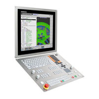
TNC 640 5E
Heidenhain TNC 640 5E Manuals
Manuals and User Guides for Heidenhain TNC 640 5E. We have
1
Heidenhain TNC 640 5E manual available for free PDF download: User Manual
Heidenhain TNC 640 5E User Manual (903 pages)
Brand:
Heidenhain
| Category:
Control Panel
| Size: 56 MB
Table of Contents
About this Manual
6
New Functions 34059X
13
The D18 Functions Have Been Expanded, See "D18 – Reading System Data
20
Table of Contents
35
First Steps with the TNC 640
65
Overview
66
Machine Switch-On
66
Acknowledging the Power Interruption and Moving to the Reference Points
66
Programming the First Part
68
Selecting the Correct Operating Mode
68
The most Important Control Keys
68
Opening a New Program/File Management
69
Defining a Workpiece Blank
70
Program Layout
71
Programming a Simple Contour
73
Creating a Cycle Program
76
Graphically Testing the First Part
78
Selecting the Correct Operating Mode
78
Selecting the Tool Table for the Test Run
78
Choosing the Program You Want to Test
79
Selecting the Screen Layout and the View
79
Starting the Test Run
80
Setting up Tools
81
Selecting the Correct Operating Mode
81
Preparing and Measuring Tools
81
The Tool Table TOOL.T
82
The Pocket Table TOOL_P .TCH
83
Workpiece Setup
84
Selecting the Correct Operating Mode
84
Clamping the Workpiece
84
Presetting with a 3-D Touch Probe
85
Running the First Program
86
Selecting the Correct Operating Mode
86
Choosing the Program You Want to Run
86
Starting the Program
86
Introduction
87
The TNC 640
88
HEIDENHAIN Klartext and DIN/ISO
88
Compatibility
88
Visual Display Unit and Operating Panel
89
Display Screen
89
Setting Screen Layout
89
Control Panel
90
Modes of Operation
91
Manual Operation and El. Handwheel
91
Positioning with Manual Data Input
91
Programming
92
Test Run
92
Program Run, Full Sequence and Program Run, Single Block
93
Status Displays
94
General Status Display
94
Additional Status Displays
96
Window Manager
103
Overview of Taskbar
104
Portscan
107
Remote Service
108
Printer
110
Selinux Security Software
112
Vnc
113
Backup and Restore
115
Remote Desktop Manager (Option 133)
118
Introduction
118
Configuring Connections - Windows Terminal Service (Remotefx)
119
Configuring the Connection - VNC
121
Shutting down or Rebooting an External Computer
122
Starting and Stopping the Connection
123
Accessories: HEIDENHAIN 3-D Touch Probes and Electronic Handwheels
124
3-D Touch Probes
124
HR Electronic Handwheels
125
Operating the Touchscreen
127
Display Unit and Operation
128
Touchscreen
128
Operating Panel
128
Gestures
129
Overview of Possible Gestures
129
Navigating in the Table and NC Programs
130
Operating the Simulation
131
Using the HEROS Menu
132
Operating the CAD Viewer
133
Functions in the Taskbar
138
Touchscreen Calibration
138
Touchscreen Configuration
138
Touchscreen Cleaning
139
Fundamentals, File Management
141
Fundamentals
142
Position Encoders and Reference Marks
142
Reference Systems
143
Designation of the Axes on Milling Machines
154
Polar Coordinates
154
Absolute and Incremental Workpiece Positions
155
Selecting the Preset
156
Creating and Writing Programs
157
Structure of an NC Program in ISO Format
157
Defining the Blank: G30/G31
158
Creating a New NC Program
161
Programming Tool Movements in DIN/ISO
162
Actual Position Capture
164
Editing an NC Program
165
The Control's Search Function
169
File Management: Basics
171
Files
171
Displaying Externally Generated Files on the Control
173
Data Backup
173
Working with the File Manager
174
Directories
174
Paths
174
Overview: Functions of the File Manager
175
Calling the File Manager
176
Selecting Drives, Directories and Files
177
Creating a New Directory
179
Creating New File
179
Copying a Single File
179
Copying Files into Another Directory
180
Copying a Table
181
Copying a Directory
182
Choosing One of the Last Files Selected
182
Deleting a File
182
Deleting a Directory
183
Tagging Files
184
Renaming a File
185
Sorting Files
185
Additional Functions
186
Additional Tools for Management of External File Types
187
Additional Tools for Itcs
195
Data Transfer to or from an External Data Carrier
197
Programming Aids
203
Adding Comments
204
Application
204
Entering Comments During Programming
204
Inserting Comments after Program Entry
204
Entering a Comment in a Separate Block
204
Commenting out an Existing NC Block
204
Functions for Editing of the Comment
205
Freely Editing an NC Program
206
Display of NC Programs
207
Syntax Highlighting
207
Scrollbar
207
Structuring Programs
208
Definition and Applications
208
Displaying the Program Structure Window / Changing the Active Window
208
Inserting a Structure Block in the Program Window
209
Selecting Blocks in the Program Structure Window
209
Calculator
210
Operation
210
Cutting Data Calculator
213
Application
213
Programming Graphics
216
Activating and Deactivating Programming Graphics
216
Generating a Graphic for an Existing Program
217
Block Number Display ON/OFF
218
Erasing the Graphic
218
Showing Grid Lines
218
Magnification or Reduction of Details
219
Error Messages
220
Display of Errors
220
Opening the Error Window
220
Closing the Error Window
220
Detailed Error Messages
221
INTERNAL INFO Soft Key
221
FILTER Soft Key
221
Clearing Errors
222
Error Log
222
Keystroke Log
223
Informational Texts
224
Saving Service Files
224
Calling the Tncguide Help System
224
Tncguide Context-Sensitive Help System
225
Application
225
Working with Tncguide
226
Downloading Current Help Files
230
Tools
233
Entering Tool-Related Data
234
Feed Rate F
234
Spindle Speed S
235
Tool Data
236
Requirements for Tool Compensation
236
Tool Number, Tool Name
236
Tool Length L
236
Tool Radius R
236
Delta Values for Lengths and Radii
237
Entering Tool Data into the NC Program
237
Entering Tool Data into the Table
238
Importing Tool Tables
248
Overwriting Tool Data from an External PC
250
Pocket Table for Tool Changer
251
Calling the Tool Data
254
Tool Change
256
Tool Usage Test
259
Tool Compensation
262
Introduction
262
Tool Length Compensation
262
Tool Radius Compensation
263
Tool Management (Option Number 93)
266
Basics
266
Calling Tool Management
267
Editing Tool Management
268
Available Tool Types
272
Importing and Exporting Tool Data
274
Programming Contours
277
Tool Movements
278
Path Functions
278
FK Free Contour Programming
278
Miscellaneous Functions M
278
Subprograms and Program Section Repeats
279
Programming with Q Parameters
279
Fundamentals of Path Functions
280
Programming Tool Movements for Workpiece Machining
280
Approaching and Departing a Contour
283
Starting Point and End Point
283
Tangential Approach and Departure
285
Overview: Types of Paths for Contour Approach and Departure
286
Important Positions for Approach and Departure
287
Approaching on a Straight Line with Tangential Connection: APPR LT
289
Approaching on a Straight Line Perpendicular to the First Contour Point: APPR LN
289
Approaching on a Circular Path with Tangential Connection: APPR CT
290
Approaching on a Circular Path with Tangential Connection from a Straight Line to the Contour: APPR LCT
291
Departing in a Straight Line with Tangential Connection: DEP LT
292
Departing in a Straight Line Perpendicular to the Last Contour Point: DEP LN
292
Departing on a Circular Path with Tangential Connection: DEP CT
293
Departing on a Circular Arc Tangentially Connecting the Contour and a Straight Line: DEP LCT
293
Path Contours Cartesian Coordinates
294
Overview of Path Functions
294
Programming Path Functions
294
Straight Line in Rapid Traverse G00 or Straight Line with Feed Rate F G01
295
Inserting a Chamfer between Two Straight Lines
296
Rounded Corners G25
297
Circle Center I, J
298
Circular Path Around Circle Center
299
Circle G02/G03/G05 with Defined Radius
300
Circle G06 with Tangential Connection
302
Example: Linear Movements and Chamfers with Cartesian Coordinates
303
Example: Circular Movements with Cartesian Coordinates
304
Example: Full Circle with Cartesian Coordinates
305
Path Contours - Polar Coordinates
306
Overview
306
Datum for Polar Coordinates: Pole I, J
307
Straight Line in Rapid Traverse G10 or Straight Line with Feed Rate F G11
307
Circular Path G12/G13/G15 Around Pole I, J
308
Circle G16 with Tangential Connection
308
Helix
309
Example: Linear Movement with Polar Coordinates
311
Example: Helix
312
Path Contours - FK Free Contour Programming
313
Fundamentals
313
FK Programming Graphics
315
Initiating the FK Dialog
316
Pole for FK Programming
316
Free Straight Line Programming
317
Free Circular Path Programming
318
Input Possibilities
319
Auxiliary Points
322
Relative Data
323
Example: FK Programming 1
325
Data Transfer from CAD Files
327
Screen Layout of the CAD Viewer
328
Fundamentals of the CAD Viewer
328
CAD Import (Option 42)
329
Application
329
Using the CAD Viewer
330
Opening the CAD File
330
Basic Settings
331
Setting Layers
333
Setting a Preset
334
Defining the Datum
336
Selecting and Saving a Contour
339
Selecting and Saving Machining Positions
343
Subprograms and Program Section Repeats
349
Labeling Subprograms and Program Section Repeats
350
Label
350
Subprograms
351
Operating Sequence
351
Programming Notes
351
Programming the Subprogram
352
Calling a Subprogram
352
Program-Section Repeats
353
Label G98
353
Operating Sequence
353
Programming Notes
353
Programming a Program Section Repeat
354
Calling a Program Section Repeat
354
Any Desired NC Program as Subprogram
355
Overview of the Soft Keys
355
Operating Sequence
356
Programming Notes
356
Calling any Program as a Subprogram
357
Nesting
360
Types of Nesting
360
Nesting Depth
360
Subprogram Within a Subprogram
361
Repeating Program Section Repeats
362
Repeating a Subprogram
363
Programming Examples
364
Example: Milling a Contour in Several Infeeds
364
Example: Groups of Holes
365
Example: Group of Holes with Several Tools
366
Programming Q Parameters
369
10.1 Principle and Overview of Functions
370
Programming Notes
372
Calling Q Parameter Functions
373
Part Families-Q Parameters in Place of Numerical Values
374
Application
374
Describing Contours with Mathematical Functions
375
Application
375
Overview
375
Programming Fundamental Operations
376
10.4 Angle Functions
378
Definitions
378
Programming Trigonometric Functions
378
10.5 Calculation of Circles
379
Application
379
10.6 If-Then Decisions with Q Parameters
380
Application
380
Unconditional Jumps
380
Programming If-Then Decisions
381
10.7 Checking and Changing Q Parameters
382
Procedure
382
Additional Functions
384
Overview
384
D14: Displaying Error Messages
385
D16 - Formatted Output of Texts and Q Parameter Values
389
D18 - Reading System Data
395
D19 - Transfer Values to the PLC
425
D20 - NC and PLC Synchronization
426
D29 - Transfer Values to the PLC
427
D37 - Export
428
D38 - Send Information from NC Program
428
Entering Formulas Directly
429
Entering Formulas
429
Rules for Formulas
431
Example of Entry
432
String Parameters
433
String Processing Functions
433
Assign String Parameters
434
Chain-Linking String Parameters
435
Converting a Numerical Value to a String Parameter
436
Copying a Substring from a String Parameter
437
Reading System Data
438
Converting a String Parameter to a Numerical Value
439
Testing a String Parameter
440
Finding the Length of a String Parameter
441
Comparing Alphabetic Priority
442
Reading out Machine Parameters
443
10.11 Preassigned Q Parameters
446
Values from the PLC: Q100 to Q107
446
Active Tool Radius: Q108
446
Tool Axis: Q109
447
Spindle Status: Q110
447
Coolant On/Off: Q111
447
Overlap Factor: Q112
447
Unit of Measurement for Dimensions in the Program: Q113
447
Tool Length: Q114
448
Coordinates after Probing During Program Run
448
Deviation between Actual Value and Nominal Value During Automatic Tool Measurement With, for Example, the TT 160
448
Tilting the Working Plane with Spatial (Workpiece) Angles Instead of Spindle Head Angles: Coordinates for Rotary Axes Calculated by the Control
448
Measurement Results from Touch Probe Cycles
449
Checking the Setup Situation: Q601
450
Programming Examples
451
Example: Ellipse
451
Example: Concave Cylinder Machined with Spherical Cutter
453
Example: Convex Sphere Machined with End Mill
455
Miscellaneous Functions
457
Entering Miscellaneous Functions M and STOP
458
Fundamentals
458
Miscellaneous Functions for Program Run Inspection, Spindle and Coolant
460
Overview
460
Miscellaneous Functions for Coordinate Entries
461
Programming Machine-Referenced Coordinates: M91/M92
461
Moving to Positions in a Non-Tilted Coordinate System with a Tilted Working Plane: M130
463
Miscellaneous Functions for Path Behavior
464
Machining Small Contour Steps: M97
464
Machining Open Contour Corners: M98
465
Feed Rate Factor for Plunging Movements: M103
466
Feed Rate in Millimeters Per Spindle Revolution: M136
467
Feed Rate for Circular Arcs: M109/M110/M111
468
Calculating the Radius-Compensated Path in Advance (LOOK AHEAD): M120
469
Superimposing Handwheel Positioning During Program Run: M118
471
Retraction from the Contour in the Tool-Axis Direction: M140
473
Suppressing Touch Probe Monitoring: M141
475
Deleting Basic Rotation: M143
476
Automatically Retracting the Tool from the Contour at an NC Stop: M148
477
Rounding Corners: M197
478
Special Functions
479
12.1 Overview of Special Functions
480
Main Menu for SPEC FCT Special Functions
480
Program Defaults Menu
481
Functions for Contour and Point Machining Menu
481
Menu for Defining Different DIN/ISO Functions
482
Dynamic Collision Monitoring (Option 40)
483
Function
483
Graphic Display of the Collision Objects
484
Collision Monitoring in the Manual Operating Modes
486
Collision Monitoring in the Test Run Operating Mode
487
Collision Monitoring in the Program Run Operating Modes
488
Activating and Deactivating Collision Monitoring
490
12.3 Tool Carrier Management
492
Fundamentals
492
Save Tool Carrier Templates
492
Assigning Input Parameters to Tool Carriers
493
Allocating Parameterized Tool Carriers
496
Global Program Settings (Option 44)
497
Application
497
Activating and Deactivating a Function
499
Information Area
502
Additive Offset (M-CS)
502
Additive Basic Rotat. (W-CS)
504
Shift (W-CS)
505
Mirroring (W-CS)
506
Shift (Mw-CS)
507
Rotation (WPL-CS)
508
Handwheel Superimp
509
Feed Rate Factor
513
Adaptive Feed Control AFC (Option 45)
514
Application
514
Defining Basic AFC Settings
516
Recording a Teach-In Cut
519
Activating and Deactivating AFC
524
Log File
526
Tool Wear Monitoring
527
Tool Load Monitoring
527
Active Chatter Control ACC (Option 145)
528
Application
528
Activating/Deactivating ACC
529
12.7 Defining DIN/ISO Functions
530
Overview
530
12.8 Defining a Counter
531
Application
531
Define FUNCTION COUNT
531
12.9 Creating Text Files
533
Application
533
Opening and Exiting a Text File
533
Editing Texts
534
Deleting and Re-Inserting Characters, Words and Lines
534
Editing Text Blocks
535
Finding Text Sections
536
12.10 Freely Definable Tables
537
Fundamentals
537
Creating a Freely Definable Table
537
Editing the Table Format
538
Switching between Table and Form View
539
D26 - Open a Freely Definable Table
540
D27 - Write to a Freely Definable Table
541
D28 - Read from a Freely Definable Table
542
Customizing the Table Format
542
Pulsing Spindle Speed FUNCTION S-PULSE
543
Programming a Pulsing Spindle Speed
543
Resetting the Pulsing Spindle Speed
544
12.12 Dwell Time FUNCTION FEED
545
Programming Dwell Time
545
Resetting Dwell Time
546
12.13 Dwell Time FUNCTION DWELL
547
Programming Dwell Time
547
Lift off Tool at NC Stop: FUNCTION LIFTOFF
548
Programming Tool Lift-Off with FUNCTION LIFTOFF
548
Resetting the Lift-Off Function
550
Multiple-Axis Machining
551
13.1 Functions for Multiple Axis Machining
552
The PLANE Function: Tilting the Working Plane (Option 8)
553
Introduction
553
Overview
555
Defining the PLANE Function
556
Position Display
556
Resetting PLANE Function
557
Defining the Working Plane with the Spatial Angle: PLANE SPATIAL
558
Defining the Working Plane with the Projection Angle: PLANE PROJECTED
560
Defining the Working Plane with the Euler Angle: PLANE EULER
562
Defining the Working Plane with Two Vectors: PLANE VECTOR
564
Defining the Working Plane Via Three Points: PLANE POINTS
567
Defining the Working Plane Via a Single Incremental Spatial Angle: PLANE RELATIV
569
Tilting the Working Plane through Axis Angle: PLANE AXIAL
570
Specifying the Positioning Behavior of the PLANE Function
572
Tilting the Working Plane Without Rotary Axes
580
Inclined-Tool Machining in a Tilted Plane (Option 9)
581
Function
581
Inclined-Tool Machining Via Incremental Traverse of a Rotary Axis
581
13.4 Miscellaneous Functions for Rotary Axes
582
Feed Rate in MM/Min on Rotary Axes A, B, C: M116 (Option 8)
582
Shortest-Path Traverse of Rotary Axes: M126
583
Reducing Display of a Rotary Axis to a Value Less than 360°: M94
584
Maintaining the Position of the Tool Tip When Positioning with Tilted Axes (TCPM): M128 (Option 9)
585
Selecting Tilting Axes: M138
588
Compensating the Machine Kinematics in ACTUAL/NOMINAL Positions at End of Block: M144 (Option 9)
589
Peripheral Milling: 3-D Radius Compensation with M128 and Radius Compensation (G41/G42)
590
Application
590
Interpretation of the Programmed Path
591
3-D Radius Compensation Depending on the Tool's Contact Angle (Option 92)
592
13.6 Running CAM Programs
594
From 3-D Model to NC Program
594
Consider with Post Processor Configuration
595
Please Note the Following for CAM Programming
597
Possibilities for Intervention on the Control
599
ADP Motion Control
600
Pallet Management
601
Pallet Management
602
Application
602
Selecting Pallet Table
606
Inserting or Deleting Columns
606
Processing Pallet Table
607
14.2 Pallet Preset Management
609
Fundamentals
609
Using Pallet Presets
609
14.3 Tool-Oriented Machining
610
Fundamentals
610
Sequence of Tool-Oriented Machining
612
MID-Program Startup with Block Scan
613
Batch Process Manager
615
Batch Process Manager (Option 154)
616
Fundamentals
616
Application
616
Opening the Batch Process Manager
619
Creating a Job List
619
Editing a Job List
621
Executing the Job List
622
Turning
623
Turning Operations on Milling Machines (Option 50)
624
Introduction
624
Basic Functions (Option 50)
625
Switching between Milling/Turning Mode of Operation
625
Graphic Display of Turning Operations
628
Program Spindle Speed
629
Feed Rate
631
Unbalance Functions (Option 50)
632
Unbalance While Turning
632
Measure Unbalance Cycle
634
Calibrate Unbalance Cycle
635
Tools in Turning Mode (Option 50)
636
Tool Call
636
Tool Compensation in the Program
637
Tool Data
638
Tool Tip Radius Compensation TRC
645
Turning Program Functions (Option 50)
647
Recessing and Undercutting
647
Blank Form Update TURNDATA BLANK
653
Inclined Turning
654
Using a Facing Slide
656
Cutting Force Monitoring with the AFC Function
660
Manual Operation and Setup
663
Switch-On, Switch-Off
664
Switch-On
664
Traverse Reference Points
666
Switch-Off
668
Moving the Machine Axes
669
Note
669
Moving the Axis with the Axis Direction Keys
669
Incremental Jog Positioning
670
Traverse with Electronic Handwheels
671
Spindle Speed S, Feed Rate F and Miscellaneous Function M
682
Application
682
Entering Values
682
Adjusting Spindle Speed and Feed Rate
683
Feed Rate Limit F MAX
683
Optional Safety Concept (Functional Safety FS)
684
Miscellaneous
684
Explanation of Terms
685
Additional Status Displays
686
Checking the Axis Positions
687
Activating Feed-Rate Limitation
688
Managing Presets
689
Note
689
Saving Presets in the Table
689
Protecting Presets from Being Overwritten
694
Activating a Preset
696
Presetting Without a 3-D Touch Probe
697
Note
697
Preparation
697
Presetting Setting with an End Mill
697
Using Touch Probe Functions with Mechanical Probes or Measuring Dials
698
Using a 3-D Touch Probe
699
Introduction
699
Overview
700
Suppress Touch Probe Monitoring
702
Functions in Touch Probe Cycles
702
Selecting the Probing Cycle
705
Recording Measured Values from the Touch Probe Cycles
705
Writing Measured Values from the Touch Probe Cycles to a Datum Table
706
Writing Measured Values from the Touch-Probe Cycles to the Preset Table
707
Calibrating 3-D Touch Probes
708
Introduction
708
Calibrating the Effective Length
709
Calibrating the Effective Radius and Compensating Center Misalignment
710
Displaying Calibration Values
714
Compensating Workpiece Misalignment with 3-D Touch Probe
715
Introduction
715
Identifying Basic Rotation
716
Saving the Basic Rotation in the Preset Table
716
Compensation of Workpiece Misalignment by Rotating the Table
717
Show Basic Rotation and Offset
718
Rescind Basic Rotation or Offset
718
Measuring 3-D Basic Rotation
719
17.10 Presetting with a 3-D Touch Probe
722
Overview
722
Presetting on any Axis
723
Corner as Preset
724
Circle Center as Preset
726
Setting a Center Line as Preset
729
Measuring Workpieces with a 3-D Touch Probe
730
Tilting the Working Plane (Option 8)
733
Application, Function
733
Position Display in a Tilted System
735
Limitations on Working with the Tilting Function
735
Activating Manual Tilting
736
Setting the Tool-Axis Direction as the Active Machining Direction
738
Setting a Preset in a Tilted Coordinate System
738
Camera-Based Monitoring of the Setup Situation VSC (Option 136)
739
Basics
739
Overview
741
Produce Live Image
742
Manage Monitoring Data
743
Configuration
745
Results of the Image Evaluation
746
Positioning with Manual Data Input
747
Programming and Executing Simple Machining Operations
748
Positioning with Manual Data Input (MDI)
749
Protecting Programs in $MDI
752
Test Run and Program Run
753
Graphics
754
Application
754
Speed of the Setting Test Runs
755
Overview: Display Modes
756
3-D View
756
Plan View
760
Projection in Three Planes
760
Repeating Graphic Simulation
762
Tool Display
762
Measurement of Machining Time
763
Showing the Workpiece Blank in the Working Space
764
Application
764
Functions for Program Display
766
Overview
766
19.4 Test Run
767
Application
767
Test Run Execution
769
Test Run up to a Certain Block
771
19.5 Program Run
772
Application
772
Running a Part Program
773
Interrupting, Stopping or Aborting Machining
774
Moving the Machine Axes During an Interruption
777
Resuming Program Run after an Interruption
778
Retraction after a Power Interruption
779
Entering the Program at any Point: MID-Program Startup
782
Returning to the Contour
787
19.6 Automatic Program Start
788
Application
788
19.7 Skipping Blocks
789
Application
789
Delete / Symbol
789
19.8 Optional Program-Run Interruption
790
Application
790
MOD Functions
791
MOD Function
792
Selecting MOD Functions
792
Changing the Settings
792
Exiting MOD Functions
792
Overview of MOD Functions
793
20.2 Graphic Settings
794
20.3 Counter Settings
795
20.4 Machine Settings
796
External Access
796
Entering Traverse Limits
798
Tool Usage File
799
Select Kinematics
800
20.5 System Settings
801
Set the System Time
801
20.6 Select the Position Display
802
Application
802
20.7 Setting the Unit of Measure
804
Application
804
20.8 Displaying Operating Times
804
20.9 Software Numbers
805
Application
805
20.10 Enter the Code Number
805
20.11 Setting up Data Interfaces
806
Serial Interfaces on the TNC 640
806
Application
806
Setting the RS-232 Interface
806
Set BAUD RATE (Baud Rate No. 106701)
806
Set Protocol (Protocol No. 106702)
807
Set Data Bits (Databits No. 106703)
807
Check Parity (Parity No. 106704)
807
Set Stop Bits (Stopbits No. 106705)
807
Set Handshake (Flowcontrol No. 106706)
808
File System for File Operation (Filesystem No. 106707)
808
Block Check Character (Bccavoidctrlchar No. 106708)
808
Condition of RTS Line (Rtslow No. 106709)
808
Define Behavior after Receipt of ETX (Noeotafteretx No. 106710)
809
Settings for the Transmission of Data Using PC Software Tncserver
809
Setting the Operating Mode of the External Device (Filesystem)
810
Software for Data Transfer
810
20.12 Ethernet Interface
812
Introduction
812
Connection Possibility
812
Configuring the Control
812
20.13 Firewall
818
Application
818
20.14 Set up Touch Probes
821
Introduction
821
Setting up a Touch Probe with Radio Transmission
821
Setting up a Touch Probe in the MOD Dialog
822
Touch Probe with Radio Transmission Configuration
823
Configuring the HR 550FS Wireless Handwheel
825
Application
825
Assigning the Handwheel to a Specific Handwheel Holder
825
Setting the Transmission Channel
826
Selecting the Transmitter Power
826
Statistical Data
827
20.16 Load Machine Configuration
828
Application
828
Tables and Overviews
829
21.1 Machine-Specific User Parameters
830
Application
830
Connector Pin Layout and Connection Cables for Data Interfaces
845
RS-232-C/V.24 Interface for HEIDENHAIN Devices
845
Non-HEIDENHAIN Devices
847
Ethernet Interface RJ45 Socket
847
21.3 Technical Information
848
User Functions
850
Software Options
853
Accessories
856
21.4 Overview Tables
857
Fixed Cycles
857
Miscellaneous Functions
859
Functions of the TNC 640 and the Itnc 530 Compared
861
Comparison: Specifications
861
Comparison: Data Interfaces
861
Comparison: PC Software
862
Comparison: User Functions
862
Comparison: Miscellaneous Functions
870
Comparator: Cycles
872
Comparison: Touch Probe Cycles in the Manual Operation and Electronic Handwheel Modes of Operation
875
Comparison: Probing System Cycles for Automatic Workpiece Control
876
Comparison: Differences in Programming
877
Comparison: Differences in Test Run, Functionality
881
Comparison: Differences in Test Run, Operation
882
Comparison: Differences in Manual Operation, Functionality
883
Comparison: Differences in Manual Operation, Operation
884
Comparison: Differences in Program Run, Operation
884
Comparison: Differences in Program Run, Traverse Movements
885
Comparison: Differences in MDI Operation
890
Comparison: Differences in Programming Station
890
21.6 DIN/ISO Function Overview
891
DIN/ISO Function Overview TNC 640
891
Advertisement
Advertisement
Related Products
HEIDENHAIN TNC 620
HEIDENHAIN TNC 620 Programming Station
HEIDENHAIN TNC 620 E
HEIDENHAIN TNC 640
HEIDENHAIN TNC 640 E
HEIDENHAIN TNC 407
HEIDENHAIN TNC 150 B
HEIDENHAIN TNC 426 B
HEIDENHAIN TNC 135 B
HEIDENHAIN TNC7
Heidenhain Categories
Media Converter
Measuring Instruments
Industrial Equipment
Control Systems
Scanner
More Heidenhain Manuals
Login
Sign In
OR
Sign in with Facebook
Sign in with Google
Upload manual
Upload from disk
Upload from URL