HEIDENHAIN TNC 320 User Manual
Cycle programming
Hide thumbs
Also See for TNC 320:
- User manual (670 pages) ,
- User's manual for cycle programming (465 pages)
Table of Contents
Advertisement
Quick Links
Download this manual
See also:
User Manual
Advertisement
Chapters
Table of Contents

Related Manuals for HEIDENHAIN TNC 320


Summary of Contents for HEIDENHAIN TNC 320
- Page 1 User’s Manual Cycle Programming TNC 320 NC Software 340 551-05 340 554-05 English (en) 12/2011...
-
Page 3: About This Manual
Would you like any changes, or have you found any errors? We are continuously striving to improve our documentation for you. Please help us by sending your requests to the following e-mail address: tnc-userdoc@heidenhain.de. HEIDENHAIN TNC 320... - Page 4 TNC users. User's Manual: All TNC functions that have no connection with cycles are described in the User's Manual of the TNC 320. Please contact HEIDENHAIN if you need a copy of this User’s Manual.
- Page 5 Software options The TNC 320 features various software options that can be enabled by your machine tool builder. Each option is to be enabled separately and contains the following respective functions: Hardware options Additional axis for 4 axes and open-loop spindle...
-
Page 6: Contents
You can purchase a code number in order to permanently enable the FCL functions. For more information, contact your machine tool builder or HEIDENHAIN. Intended place of operation The TNC complies with the limits for a Class A device in accordance with the specifications in EN 55022, and is intended for use primarily in industrially-zoned areas. - Page 7 Datum tables can now also be selected in the machine operating modes Program Run, Full Sequence and Program Run, Single Block (STATUS M). The definition of feed rates in fixed cycles can now also include FU and FZ values HEIDENHAIN TNC 320...
- Page 8 The PLANE function for flexible definition of a tilted working place was introduced (see User’s Manual for Conversational Programming) The context-sensitive help system TNCguide was introduced (see User’s Manual for Conversational Programming) The FUNCTION PARAX function for defining the behavior of the parallel axes U, V and W was introduced (see User’s Manual for Conversational Programming) The conversational languages Slovak, Norwegian, Latvian, Korean,...
- Page 9 The tolerance values set in Cycle 32 are displayed. Tool changes are now also possible during mid-program startup. Language-sensitive texts can now be output with FN16 F-Print. The soft-key structure of the SPEC FCT function was changed and adapted to the iTNC 530. HEIDENHAIN TNC 320...
- Page 10 340 55x-05 The function M101 was introduced (see User’s Manual for Conversational Programming). Tool tables of the iTNC 530 can now be imported in the TNC 320 and converted to a valid format (see User’s Manual for Conversational Programming). The CYCL CALL POS function was introduced (see "Calling a cycle with CYCL CALL POS"...
- Page 11 Manual for Conversational Programming). The graphic simulation was extended and adapted to the iTNC 530 (see User’s Manual for Conversational Programming). Touch probe cycles can now also be used in the tilted working plane (see User’s Manual for Conversational Programming). HEIDENHAIN TNC 320...
-
Page 13: Table Of Contents
Cycles: Special Functions Using Touch Probe Cycles Touch Probe Cycles: Automatic Measure- ment of Workpiece Misalignment Touch Probe Cycles: Automatic Datum Setting Touch Probe Cycles: Automatic Workpiece Inspection Touch Probe Cycles: Special Functions Touch Probe Cycles: Automatic Tool Measurement HEIDENHAIN TNC 320... -
Page 15: Fundamentals / Overviews
1 Fundamentals / Overviews ..37 1.1 Introduction ..38 1.2 Available Cycle Groups ..39 Overview of fixed cycles ..39 Overview of touch probe cycles ..40 HEIDENHAIN TNC 320... -
Page 16: Using Fixed Cycles
2 Using Fixed Cycles ..41 2.1 Working with Fixed Cycles ..42 Machine-specific cycles ..42 Defining a cycle using soft keys ..43 Defining a cycle using the GOTO function ..43 Calling cycles ..44 2.2 Pattern Definition PATTERN DEF ..46 Application .. -
Page 17: Fixed Cycles: Drilling
Please note while programming: ..84 Cycle parameters ..85 3.10 SINGLE-LIP DEEP-HOLE DRILLING (Cycle 241, DIN/ISO: G241) ..86 Cycle run ..86 Please note while programming: ..86 Cycle parameters ..87 3.11 Programming Examples ..89 HEIDENHAIN TNC 320... -
Page 18: Fixed Cycles: Tapping / Thread Milling 5
4 Fixed Cycles: Tapping / Thread Milling ..93 4.1 Fundamentals ..94 Overview ..94 4.2 TAPPING NEW with a Floating Tap Holder (Cycle 206, DIN/ISO: G206) ..95 Cycle run ..95 Please note while programming: ..95 Cycle parameters .. -
Page 19: Fixed Cycles: Pocket Milling / Stud Milling / Slot Milling
Please note while programming: ..149 Cycle parameters ..150 5.7 CIRCULAR STUD (Cycle 257, DIN/ISO: G257) ..152 Cycle run ..152 Please note while programming: ..153 Cycle parameters ..154 5.8 Programming Examples ..156 HEIDENHAIN TNC 320... -
Page 20: Fixed Cycles: Pattern Definitions
6 Fixed Cycles: Pattern Definitions ..159 6.1 Fundamentals ..160 Overview ..160 6.2 POLAR PATTERN (Cycle 220, DIN/ISO: G220) ..161 Cycle run ..161 Please note while programming: ..161 Cycle parameters ..162 6.3 CARTESIAN PATTERN (Cycle 221, DIN/ISO: G221) ..164 Cycle run .. -
Page 21: Fixed Cycles: Contour Pocket
Please note while programming: ..186 Cycle parameters ..187 7.9 CONTOUR TRAIN (Cycle 25, DIN/ISO: G125) ..188 Cycle run ..188 Please note while programming: ..188 Cycle parameters ..189 7.10 Programming Examples ..190 HEIDENHAIN TNC 320... -
Page 22: Fixed Cycles: Cylindrical Surface
8 Fixed Cycles: Cylindrical Surface ..197 8.1 Fundamentals ..198 Overview of cylindrical surface cycles ..198 8.2 CYLINDER SURFACE (Cycle 27, DIN/ISO: G127, Software Option 1) ..199 Execution of cycle ..199 Please note while programming: ..200 Cycle parameters .. -
Page 23: Fixed Cycles: Contour Pocket With
Overlapping contours ..218 Contour machining with SL Cycles ..220 9.2 SL Cycles with Simple Contour Formula ..224 Fundamentals ..224 Entering a simple contour formula ..225 Contour machining with SL Cycles ..225 HEIDENHAIN TNC 320... -
Page 24: Fixed Cycles: Multipass Milling
10 Fixed Cycles: Multipass Milling ..227 10.1 Fundamentals ..228 Overview ..228 10.2 MULTIPASS MILLING (Cycle 230, DIN/ISO: G230) ..229 Cycle run ..229 Please note while programming: ..229 Cycle parameters ..230 10.3 RULED SURFACE (Cycle 231, DIN/ISO: G231) ..231 Cycle run .. -
Page 25: Cycles: Coordinate Transformations
Cycle parameters ..255 11.7 SCALING (Cycle 11, DIN/ISO: G72) ..256 Effect ..256 Cycle parameters ..257 11.8 AXIS-SPECIFIC SCALING (Cycle 26) ..258 Effect ..258 Please note while programming: ..258 Cycle parameters ..259 HEIDENHAIN TNC 320... - Page 26 11.9 WORKING PLANE (Cycle 19, DIN/ISO: G80, Software Option 1) ..260 Effect ..260 Please note while programming: ..261 Cycle parameters ..261 Resetting ..261 Positioning the axes of rotation ..262 Position display in the tilted system ..264 Workspace monitoring ..
-
Page 27: Cycles: Special Functions
Cycle parameters ..274 12.5 TOLERANCE (Cycle 32, DIN/ISO: G62) ..275 Cycle function ..275 Influences of the geometry definition in the CAM system ..276 Please note while programming: ..277 Cycle parameters ..278 HEIDENHAIN TNC 320... -
Page 28: Using Touch Probe Cycles
13 Using Touch Probe Cycles ..279 13.1 General Information about Touch Probe Cycles ..280 Method of function ..280 Consideration of a basic rotation in the Manual Operation mode ..280 Cycles in the Manual and El. Handwheel modes ..280 Touch probe cycles for automatic operation .. - Page 29 Cycle run ..304 Cycle parameters ..304 14.7 Compensating Workpiece Misalignment by Rotating the C Axis (Cycle 405, DIN/ISO: G405) ..305 Cycle run ..305 Please note while programming: ..306 Cycle parameters ..307 HEIDENHAIN TNC 320...
- Page 30 15 Touch Probe Cycles: Automatic Datum Setting ..311 15.1 Fundamentals ..312 Overview ..312 Characteristics common to all touch probe cycles for datum setting ..313 15.2 SLOT CENTER REF PT (Cycle 408, DIN/ISO: G408) ..315 Cycle run ..315 Please note while programming: ..
- Page 31 Cycle run ..353 Please note while programming: ..354 Cycle parameters ..354 15.13 DATUM IN ONE AXIS (Cycle 419, DIN/ISO: G419) ..357 Cycle run ..357 Please note while programming: ..357 Cycle parameters ..358 HEIDENHAIN TNC 320...
- Page 32 16 Touch Probe Cycles: Automatic Workpiece Inspection ..365 16.1 Fundamentals ..366 Overview ..366 Recording the results of measurement ..367 Measurement results in Q parameters ..369 Classification of results ..369 Tolerance monitoring ..370 Tool monitoring ..370 Reference system for measurement results ..
- Page 33 Please note while programming: ..403 Cycle parameters ..404 16.13 MEASURE PLANE (Cycle 431, DIN/ISO: G431) ..407 Cycle run ..407 Please note while programming: ..408 Cycle parameters ..408 16.14 Programming Examples ..410 HEIDENHAIN TNC 320...
-
Page 34: Touch Probe Cycles: Special Functions
17 Touch Probe Cycles: Special Functions ..415 17.1 Fundamentals ..416 Overview ..416 17.2 MEASURING (Cycle 3) ..417 Cycle run ..417 Please note while programming: ..417 Cycle parameters ..418... -
Page 35: Touch Probe Cycles: Automatic Tool Measurement
Please note while programming: ..428 Cycle parameters ..429 18.5 Measuring Tool Length and Radius (Cycle 33 or 483, DIN/ISO: G483) ..430 Cycle run ..430 Please note while programming: ..430 Cycle parameters ..431 HEIDENHAIN TNC 320... - Page 37 Fundamentals / Overviews...
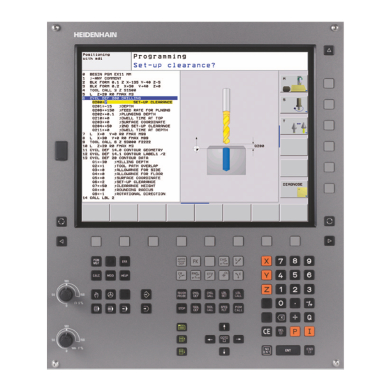
- Page 38 1.1 Introduction Frequently recurring machining cycles that comprise several working steps are stored in the TNC memory as standard cycles. Coordinate transformations and several special functions are also available as cycles. Most cycles use Q parameters as transfer parameters. Parameters with specific functions that are required in several cycles always have the same number: For example, Q200 is always assigned the set-up clearance, Q202 the plunging depth, etc.
- Page 39 Special cycles such as dwell time, program call, oriented spindle stop and tolerance Page 270 If required, switch to machine-specific fixed cycles. These fixed cycles can be integrated by your machine tool builder. HEIDENHAIN TNC 320...
- Page 40 Overview of touch probe cycles The soft-key row shows the available groups of cycles Cycle group Soft key Page Cycles for automatic measurement and compensation of workpiece misalignment Page 290 Cycles for automatic workpiece presetting Page 312 Cycles for automatic workpiece inspection Page 366 Special cycles Page 416...
- Page 41 Using Fixed Cycles...
- Page 42 2.1 Working with Fixed Cycles Machine-specific cycles In addition to the HEIDENHAIN cycles, many machine tool builders offer their own cycles in the TNC. These cycles are available in a separate cycle-number range: Cycles 300 to 399 Machine-specific cycles that are to be defined through the...
- Page 43 Example NC blocks 7 CYCL DEF 200 DRILLING Q200=2 ;SET-UP CLEARANCE Q201=3 ;DEPTH Q206=150 ;FEED RATE FOR PLNGNG Q202=5 ;PLUNGING DEPTH Q210=0 ;DWELL TIME AT TOP Q203=+0 ;SURFACE COORDINATE Q204=50 ;2ND SET-UP CLEARANCE Q211=0.25 ;DWELL TIME AT DEPTH HEIDENHAIN TNC 320...
- Page 44 Calling cycles Prerequisites The following data must always be programmed before a cycle call: BLK FORM for graphic display (needed only for test graphics) Tool call Direction of spindle rotation (M functions M3/M4) Cycle definition (CYCL DEF) For some cycles, additional prerequisites must be observed.
- Page 45 M89. To cancel the effect of M89, program: M99 in the positioning block in which you move to the last starting point, or Use CYCL DEF to define a new fixed cycle. HEIDENHAIN TNC 320...
- Page 46 2.2 Pattern Definition PATTERN DEF Application You use the PATTERN DEF function to easily define regular machining patterns, which you can call with the CYCL CALL PAT function. As with the cycle definitions, support graphics that illustrate the respective input parameter are also available for pattern definitions. PATTERN DEF is to be used only in connection with the tool axis Z.
- Page 47 SEL PATTERN function. You can use the mid-program startup function to select any point at which you want to start or continue machining (see User's Manual, Test Run and Program Run sections). HEIDENHAIN TNC 320...
- Page 48 Defining individual machining positions You can enter up to 9 machining positions. Confirm each entry with the ENT key. If you have defined a workpiece surface in Z not equal to 0, then this value is effective in addition to the workpiece surface Q203 that you defined in the machining cycle.
- Page 49 Reference axis: Major axis of the active machining plane (e.g. X for tool axis Z). You can enter a positive or negative value. Workpiece surface coordinate (absolute): Enter Z coordinate at which machining is to begin HEIDENHAIN TNC 320...
- Page 50 Defining a single pattern If you have defined a workpiece surface in Z not equal to 0, then this value is effective in addition to the workpiece surface Q203 that you defined in the machining cycle. The Rotary pos. ref. ax. and Rotary pos. minor ax. parameters are added to a previously performed rotated position of the entire pattern.
- Page 51 You can enter a positive or negative value. Workpiece surface coordinate (absolute): Enter Z coordinate at which machining is to begin HEIDENHAIN TNC 320...
- Page 52 Defining a full circle If you have defined a workpiece surface in Z not equal to 0, then this value is effective in addition to the workpiece surface Q203 that you defined in the machining cycle. Example: NC blocks Bolt-hole circle center X (absolute): Coordinate of the circle center in the X axis 10 L Z+100 R0 FMAX Bolt-hole circle center Y (absolute): Coordinate of...
- Page 53 As an alternative you can enter the end angle (switch via soft key). Number of repetitions: Total number of machining positions on the circle Workpiece surface coordinate (absolute): Enter Z coordinate at which machining is to begin HEIDENHAIN TNC 320...
- Page 54 2.3 Point Tables Function You should create a point table whenever you want to run a cycle, or several cycles in sequence, on an irregular point pattern. If you are using drilling cycles, the coordinates of the working plane in the point table represent the hole centers.
- Page 55 In the FADE column of the point table you can specify if the defined point is to be hidden during the machining process. In the table, select the point to be hidden. Select the FADE column. Activate hiding, or Deactivate hiding. HEIDENHAIN TNC 320...
- Page 56 Selecting a point table in the program In the Programming and Editing mode of operation, select the program for which you want to activate the point table: Press the PGM CALL key to call the function for selecting the point table. Press the POINT TABLE soft key.
- Page 57 The TNC interprets the points of the working plane as coordinates of the cycle starting point. If you want to use the coordinate defined in the point table for the spindle axis as the starting point coordinate, you must define the workpiece surface coordinate (Q203) as 0. HEIDENHAIN TNC 320...
- Page 58 Using Fixed Cycles...
- Page 59 Fixed Cycles: Drilling...
- Page 60 3.1 Fundamentals Overview The TNC offers 9 cycles for all types of drilling operations: Cycle Soft key Page 240 CENTERING Page 61 With automatic pre-positioning, 2nd set-up clearance, optional entry of the centering diameter or centering depth 200 DRILLING Page 63 With automatic pre-positioning, 2nd set-up clearance 201 REAMING...
-
Page 61: Centering
Keep in mind that the TNC reverses the calculation for pre- positioning when a positive diameter or depth is entered. This means that the tool moves at rapid traverse in the tool axis to set-up clearance below the workpiece surface! HEIDENHAIN TNC 320... - Page 62 Cycle parameters Set-up clearance Q200 (incremental): Distance between tool tip and workpiece surface. Enter a positive value. Input range 0 to 99999.9999 Select depth/diameter (0/1) Q343: Select whether centering is based on the entered diameter or depth. If the TNC is to center based on the entered diameter, the point angle of the tool must be defined in the T-ANGLE column of the tool table TOOL.T.
-
Page 63: Drilling
Keep in mind that the TNC reverses the calculation for pre- positioning when a positive depth is entered. This means that the tool moves at rapid traverse in the tool axis to set-up clearance below the workpiece surface! HEIDENHAIN TNC 320... -
Page 64: 2Nd Set-Up Clearance
Cycle parameters Set-up clearance Q200 (incremental): Distance between tool tip and workpiece surface. Enter a positive value. Input range 0 to 99999.9999 Depth Q201 (incremental): Distance between workpiece surface and bottom of hole (tip of drill taper). Input range -99999.9999 to 99999.9999 Feed rate for plunging Q206: Traversing speed of the tool during drilling in mm/min. -
Page 65: Reaming
Keep in mind that the TNC reverses the calculation for pre- positioning when a positive depth is entered. This means that the tool moves at rapid traverse in the tool axis to set-up clearance below the workpiece surface! HEIDENHAIN TNC 320... -
Page 66: 2Nd Set-Up Clearance
Cycle parameters Set-up clearance Q200 (incremental): Distance between tool tip and workpiece surface. Input range 0 to 99999.9999 Depth Q201 (incremental): Distance between workpiece surface and bottom of hole. Input range -99999.9999 to 99999.9999 Feed rate for plunging Q206: Traversing speed of the tool during reaming in mm/min. -
Page 67: Boring
6 The TNC moves the tool at the retraction feed rate to the set-up clearance and then, if entered, to the 2nd set-up clearance at FMAX. If Q214=0, the tool point remains on the wall of the hole. HEIDENHAIN TNC 320... - Page 68 Please note while programming: Machine and TNC must be specially prepared by the machine tool builder for use of this cycle. This cycle is effective only for machines with servo- controlled spindle. Program a positioning block for the starting point (hole center) in the working plane with radius compensation R0.
-
Page 69: 2Nd Set-Up Clearance
Workpiece surface coordinate Q203 (absolute): Coordinate of the workpiece surface. Input range -99999.9999 to 99999.9999 2nd set-up clearance Q204 (incremental): Coordinate in the spindle axis at which no collision between tool and workpiece (fixtures) can occur. Input range 0 to 99999.999 HEIDENHAIN TNC 320... - Page 70 Disengaging direction (0/1/2/3/4) Q214: Determine the direction in which the TNC retracts the tool at the hole bottom (after spindle orientation). Do not retract tool. Retract tool in the negative ref. axis direction. Retract tool in the negative minor axis direction. Retract tool in the positive ref.
-
Page 71: Universal Drilling
6 The tool remains at the hole bottom—if programmed—for the entered dwell time to cut free, and then retracts to the set-up clearance at the retraction feed rate. If programmed, the tool moves to the 2nd set-up clearance at FMAX. HEIDENHAIN TNC 320... - Page 72 Please note while programming: Program a positioning block for the starting point (hole center) in the working plane with radius compensation R0. The algebraic sign for the cycle parameter DEPTH determines the working direction. If you program DEPTH=0, the cycle will not be executed. Danger of collision! Use the machine parameter displayDepthErr to define whether, if a positive depth is entered, the TNC should...
- Page 73 (fixtures) can occur. Input range 0 to 99999.9999 Decrement Q212 (incremental): Value by which the TNC decreases the plunging depth Q202 after each infeed. Input range 0 to 99999.9999 HEIDENHAIN TNC 320...
- Page 74 Example: NC blocks No. of breaks before retracting Q213: Number of chip breaks after which the TNC is to withdraw the 11 CYCL DEF 203 UNIVERSAL DRILLING tool from the hole for chip removal. For chip breaking, the TNC retracts the tool each time by the Q200=2 ;SET-UP CLEARANCE value in Q256.
-
Page 75: Back Boring
6 The TNC moves the tool at the pre-positioning feed rate to the set- up clearance and then—if entered—to the 2nd set-up clearance at FMAX. HEIDENHAIN TNC 320... - Page 76 Please note while programming: Machine and TNC must be specially prepared by the machine tool builder for use of this cycle. This cycle is effective only for machines with servo- controlled spindle. Special boring bars for upward cutting are required for this cycle.
- Page 77 Feed rate for back boring Q254: Traversing speed of the tool during back boring in mm/min. Input range 0 to 99999.999; alternatively FAUTO, FU Dwell time Q255: Dwell time in seconds at the top of the bore hole. Input range 0 to 3600.000 HEIDENHAIN TNC 320...
- Page 78 Example: NC blocks Workpiece surface coordinate Q203 (absolute): Coordinate of the workpiece surface. Input range 11 CYCL DEF 204 BACK BORING -99999.9999 to 99999.9999 Q200=2 ;SET-UP CLEARANCE 2nd set-up clearance Q204 (incremental): Coordinate in the spindle axis at which no collision between tool Q249=+5 ;DEPTH OF COUNTERBORE and workpiece (fixtures) can occur.
-
Page 79: Universal Pecking
7 The tool remains at the hole bottom—if programmed—for the entered dwell time to cut free, and then retracts to the set-up clearance at the retraction feed rate. If programmed, the tool moves to the 2nd set-up clearance at FMAX. HEIDENHAIN TNC 320... - Page 80 Please note while programming: Program a positioning block for the starting point (hole center) in the working plane with radius compensation R0. The algebraic sign for the cycle parameter DEPTH determines the working direction. If you program DEPTH=0, the cycle will not be executed. If you enter different advance stop distances for Q258 and Q259, the TNC will change the advance stop distances between the first and last plunging depths at the same...
- Page 81 Lower advanced stop distance Q259 (incremental): Set-up clearance for rapid traverse positioning when the TNC moves the tool again to the current plunging depth after retraction from the hole; value for the last plunging depth. Input range 0 to 99999.9999 HEIDENHAIN TNC 320...
- Page 82 Example: NC blocks Infeed depth for chip breaking Q257 (incremental): Depth at which the TNC carries out chip breaking. No 11 CYCL DEF 205 UNIVERSAL PECKING chip breaking if 0 is entered. Input range 0 to 99999.9999 Q200=2 ;SET-UP CLEARANCE Retraction rate for chip breaking Q256 Q201=-80 ;DEPTH (incremental): Value by which the TNC retracts the...
-
Page 83: Bore Milling
4 The TNC then positions the tool at the center of the hole again. 5 Finally the TNC returns to the set-up clearance at FMAX. If programmed, the tool moves to the 2nd set-up clearance at FMAX. HEIDENHAIN TNC 320... - Page 84 Please note while programming: Program a positioning block for the starting point (hole center) in the working plane with radius compensation R0. The algebraic sign for the cycle parameter DEPTH determines the working direction. If you program DEPTH=0, the cycle will not be executed. If you have entered the bore hole diameter to be the same as the tool diameter, the TNC will bore directly to the entered depth without any helical interpolation.
-
Page 85: 2Nd Set-Up Clearance
12 CYCL DEF 208 BORE MILLING –1 = up-cut milling Q200=2 ;SET-UP CLEARANCE Q201=-80 ;DEPTH Q206=150 ;FEED RATE FOR PLNGNG Q334=1.5 ;PLUNGING DEPTH Q203=+100 ;SURFACE COORDINATE Q204=50 ;2ND SET-UP CLEARANCE Q335=25 ;NOMINAL DIAMETER Q342=0 ;ROUGHING DIAMETER Q351=+1 ;CLIMB OR UP-CUT HEIDENHAIN TNC 320... -
Page 86: Single-Lip Deep-Hole
3.10 SINGLE-LIP DEEP-HOLE DRILLING (Cycle 241, DIN/ISO: G241) Cycle run 1 The TNC positions the tool in the tool axis at rapid traverse FMAX to the programmed set-up clearance above the workpiece surface. 2 Then the TNC moves the tool at the defined positioning feed rate to the set-up clearance above the deepened starting point and activates the drilling speed (M3) and the coolant. - Page 87 Retraction feed rate Q208: Traversing speed of the tool in mm/min when retracting from the hole. If you enter Q208 = 0, the TNC retracts the tool at the feed rate in Q206. Input range 0 to 99999.999, alternatively FMAX, FAUTO HEIDENHAIN TNC 320...
-
Page 88: Drilling
Example: NC blocks Rotat. dir. of entry/exit (3/4/5) Q426: Desired direction of spindle rotation when tool moves into and 11 CYCL DEF 241 SINGLE-LIP DEEP-HOLE retracts from the hole. Input range: DRILLING 3: Spindle rotation with M3 4: Spindle rotation with M4 Q200=2 ;SET-UP CLEARANCE 5: Movement with stationary spindle... - Page 89 5 CYCL DEF 200 DRILLING Cycle definition Q200=2 ;SET-UP CLEARANCE Q201=-15 ;DEPTH Q206=250 ;FEED RATE FOR PLNGNG Q202=5 ;PLUNGING DEPTH Q210=0 ;DWELL TIME AT TOP Q203=-10 ;SURFACE COORDINATE Q204=20 ;2ND SET-UP CLEARANCE Q211=0.2 ;DWELL TIME AT DEPTH HEIDENHAIN TNC 320...
- Page 90 6 L X+10 Y+10 R0 FMAX M3 Approach hole 1, spindle ON 7 CYCL CALL Cycle call 8 L Y+90 R0 FMAX M99 Approach hole 2, call cycle 9 L X+90 R0 FMAX M99 Approach hole 3, call cycle 10 L Y+10 R0 FMAX M99 Approach hole 4, call cycle 11 L Z+250 R0 FMAX M2 Retract in the tool axis, end program...
- Page 91 POS1( X+10 Y+10 Z+0 ) POS2( X+40 Y+30 Z+0 ) POS3( X+20 Y+55 Z+0 ) POS4( X+10 Y+90 Z+0 ) POS5( X+90 Y+90 Z+0 ) POS6( X+80 Y+65 Z+0 ) POS7( X+80 Y+30 Z+0 ) POS8( X+90 Y+10 Z+0 ) HEIDENHAIN TNC 320...
- Page 92 6 CYCL DEF 240 CENTERING Cycle definition: CENTERING Q200=2 ;SET-UP CLEARANCE Q343=0 ;SELECT DEPTH/DIA. Q201=-2 ;DEPTH Q344=-10 ;DIAMETER Q206=150 ;FEED RATE FOR PLNGN Q211=0 ;DWELL TIME AT DEPTH Q203=+0 ;SURFACE COORDINATE Q204=50 ;2ND SET-UP CLEARANCE 7 CYCL CALL PAT F5000 M13 Call the cycle in connection with the hole pattern 8 L Z+100 R0 FMAX Retract the tool, change the tool...
- Page 93 Fixed Cycles: Tapping / Thread Milling...
- Page 94 4.1 Fundamentals Overview The TNC offers 8 cycles for all types of threading operations: Cycle Soft key Page 206 TAPPING NEW Page 95 With a floating tap holder, with automatic pre-positioning, 2nd set-up clearance 207 RIGID TAPPING NEW Page 97 Without a floating tap holder, with automatic pre-positioning, 2nd setup clearance...
- Page 95 Keep in mind that the TNC reverses the calculation for pre- positioning when a positive depth is entered. This means that the tool moves at rapid traverse in the tool axis to set-up clearance below the workpiece surface! HEIDENHAIN TNC 320...
- Page 96 Cycle parameters Set-up clearance Q200 (incremental): Distance between tool tip (at starting position) and workpiece surface. Standard value: approx. 4 times the thread pitch. Input range 0 to 99999.9999 Total hole depth Q201 (thread length, incremental): Distance between workpiece surface and end of thread.
- Page 97 If programmed, the tool moves to the 2nd set-up clearance at FMAX. 4 The TNC brings spindle rotation to a stop at the set-up clearance. HEIDENHAIN TNC 320...
- Page 98 Please note while programming: Machine and TNC must be specially prepared by the machine tool builder for use of this cycle. This cycle is effective only for machines with servo- controlled spindle. Program a positioning block for the starting point (hole center) in the working plane with radius compensation R0.
- Page 99 TNC will display the MANUAL OPERATION soft key. If you press the MANUAL OPERATION key, you can retract the tool Q203=+25 ;SURFACE COORDINATE under program control. Simply press the positive axis direction button Q204=50 ;2ND SET-UP CLEARANCE of the active spindle axis. HEIDENHAIN TNC 320...
- Page 100 4.4 TAPPING WITH CHIP BREAKING (Cycle 209, DIN/ISO: G209) Cycle run The TNC machines the thread in several passes until it reaches the programmed depth. You can define in a parameter whether the tool is to be retracted completely from the hole for chip breaking. 1 The TNC positions the tool in the tool axis at rapid traverse FMAX to the programmed set-up clearance above the workpiece surface.
- Page 101 Keep in mind that the TNC reverses the calculation for pre- positioning when a positive depth is entered. This means that the tool moves at rapid traverse in the tool axis to set-up clearance below the workpiece surface! HEIDENHAIN TNC 320...
- Page 102 Cycle parameters Set-up clearance Q200 (incremental): Distance between tool tip (at starting position) and workpiece surface. Input range 0 to 99999.9999 Thread depth Q201 (incremental): Distance between workpiece surface and end of thread. Input range -99999.9999 to 99999.9999 Pitch Q239 Pitch of the thread.
- Page 103 The machining direction of the thread changes if you execute a thread milling cycle in connection with Cycle 8 MIRROR IMAGE in only one axis. HEIDENHAIN TNC 320...
- Page 104 Danger of collision! Always program the same algebraic sign for the infeeds: Cycles comprise several sequences of operation that are independent of each other. The order of precedence according to which the work direction is determined is described with the individual cycles. For example, if you only want to repeat the countersinking process of a cycle, enter 0 for the thread depth.
- Page 105 5 After this, the tool departs the contour tangentially and returns to the starting point in the working plane. 6 At the end of the cycle, the TNC retracts the tool at rapid traverse to the setup clearance, or—if programmed—to the 2nd setup clearance. HEIDENHAIN TNC 320...
- Page 106 Please note while programming: Program a positioning block for the starting point (hole center) in the working plane with radius compensation R0. The algebraic sign for the cycle parameter "thread depth" determines the working direction. If you program the thread DEPTH = 0, the cycle will not be executed. The nominal thread diameter is approached in a semi-circle from the center.
- Page 107 ;THREADS PER STEP tool during milling in mm/min. Input range 0 to Q253=750 ;F PRE-POSITIONING 99999.999; alternatively FAUTO Q351=+1 ;CLIMB OR UP-CUT Q200=2 ;SET-UP CLEARANCE Q203=+30 ;SURFACE COORDINATE Q204=50 ;2ND SET-UP CLEARANCE Q207=500 ;FEED RATE FOR MILLING HEIDENHAIN TNC 320...
- Page 108 4.7 THREAD MILLING/COUNTERSINKING (Cycle 263, DIN/ISO: G263) Cycle run 1 The TNC positions the tool in the tool axis at rapid traverse FMAX to the programmed set-up clearance above the workpiece surface. Countersinking 2 The tool moves at the feed rate for pre-positioning to the countersinking depth minus the set-up clearance, and then at the feed rate for countersinking to the countersinking depth.
- Page 109 Keep in mind that the TNC reverses the calculation for pre- positioning when a positive depth is entered. This means that the tool moves at rapid traverse in the tool axis to set-up clearance below the workpiece surface! HEIDENHAIN TNC 320...
- Page 110 Cycle parameters Nominal diameter Q335: Nominal thread diameter. Input range 0 to 99999.9999 Thread pitch Q239: Pitch of the thread. The algebraic sign differentiates between right-hand and left-hand threads: += right-hand thread – = left-hand thread Input range -99.9999 to 99.9999 Thread depth Q201 (incremental): Distance between workpiece surface and root of thread.
- Page 111 Input range 0 to 99999.9999; alternatively FAUTO Q357=0.2 ;CLEARANCE TO SIDE Q358=+0 ;DEPTH AT FRONT Q359=+0 ;OFFSET AT FRONT Q203=+30 ;SURFACE COORDINATE Q204=50 ;2ND SET-UP CLEARANCE Q254=150 ;F COUNTERSINKING Q207=500 ;FEED RATE FOR MILLING HEIDENHAIN TNC 320...
- Page 112 4.8 THREAD DRILLING/MILLING (Cycle 264, DIN/ISO: G264) Cycle run 1 The TNC positions the tool in the tool axis at rapid traverse FMAX to the programmed set-up clearance above the workpiece surface. Drilling 2 The tool drills to the first plunging depth at the programmed feed rate for plunging.
- Page 113 Keep in mind that the TNC reverses the calculation for pre- positioning when a positive depth is entered. This means that the tool moves at rapid traverse in the tool axis to set-up clearance below the workpiece surface! HEIDENHAIN TNC 320...
- Page 114 Cycle parameters Nominal diameter Q335: Nominal thread diameter. Input range 0 to 99999.9999 Thread pitch Q239: Pitch of the thread. The algebraic sign differentiates between right-hand and left-hand threads: += right-hand thread – = left-hand thread Input range -99.9999 to 99.9999 Thread depth Q201 (incremental): Distance between workpiece surface and root of thread.
- Page 115 ;DEPTH FOR CHIP BRKNG Q256=0.2 ;DIST FOR CHIP BRKNG Q358=+0 ;DEPTH AT FRONT Q359=+0 ;OFFSET AT FRONT Q200=2 ;SET-UP CLEARANCE Q203=+30 ;SURFACE COORDINATE Q204=50 ;2ND SET-UP CLEARANCE Q206=150 ;FEED RATE FOR PLNGNG Q207=500 ;FEED RATE FOR MILLING HEIDENHAIN TNC 320...
- Page 116 4.9 HELICAL THREAD DRILLING/MILLING (Cycle 265, DIN/ISO: G265) Cycle run 1 The TNC positions the tool in the tool axis at rapid traverse FMAX to the programmed set-up clearance above the workpiece surface. Countersinking at front 2 If countersinking is before thread milling, the tool moves at the feed rate for countersinking to the sinking depth at front.
- Page 117 Keep in mind that the TNC reverses the calculation for pre- positioning when a positive depth is entered. This means that the tool moves at rapid traverse in the tool axis to set-up clearance below the workpiece surface! HEIDENHAIN TNC 320...
- Page 118 Cycle parameters Nominal diameter Q335: Nominal thread diameter. Input range 0 to 99999.9999 Thread pitch Q239: Pitch of the thread. The algebraic sign differentiates between right-hand and left-hand threads: += right-hand thread –= left-hand thread Input range -99.9999 to 99.9999 Thread depth Q201 (incremental): Distance between workpiece surface and root of thread.
- Page 119 Feed rate for milling Q207: Traversing speed of the Q360=0 ;COUNTERSINK tool during milling in mm/min. Input range 0 to 99999.999; alternatively FAUTO Q200=2 ;SET-UP CLEARANCE Q203=+30 ;SURFACE COORDINATE Q204=50 ;2ND SET-UP CLEARANCE Q254=150 ;F COUNTERSINKING Q207=500 ;FEED RATE FOR MILLING HEIDENHAIN TNC 320...
- Page 120 4.10 OUTSIDE THREAD MILLING (Cycle 267, DIN/ISO: G267) Cycle run 1 The TNC positions the tool in the tool axis at rapid traverse FMAX to the programmed set-up clearance above the workpiece surface. Countersinking at front 2 The TNC moves in the reference axis of the working plane from the center of the stud to the starting point for countersinking at front.
- Page 121 Keep in mind that the TNC reverses the calculation for pre- positioning when a positive depth is entered. This means that the tool moves at rapid traverse in the tool axis to set-up clearance below the workpiece surface! HEIDENHAIN TNC 320...
- Page 122 Cycle parameters Nominal diameter Q335: Nominal thread diameter. Input range 0 to 99999.9999 Thread pitch Q239: Pitch of the thread. The algebraic sign differentiates between right-hand and left-hand threads: += right-hand thread – = left-hand thread Input range -99.9999 to 99.9999 Thread depth Q201 (incremental): Distance between workpiece surface and root of thread.
- Page 123 Input range 0 to 99999.999; alternatively FAUTO, FU Feed rate for milling Q207: Traversing speed of the tool during milling in mm/min. Input range 0 to 99999.999; alternatively FAUTO HEIDENHAIN TNC 320...
- Page 124 4.11 Programming Examples Example: Thread milling The drill hole coordinates are stored in the point table TAB1.PNT and are called by the TNC with CYCL CALL PAT. The tool radii are selected so that all work steps can be seen in the test graphics. Program sequence Centering Drilling...
- Page 125 0 must be entered here, effective as defined in point table 20 CYCL CALL PAT F5000 M3 Cycle call in connection with point table TAB1.PNT 21 L Z+100 R0 FMAX M2 Retract in the tool axis, end program 22 END PGM 1 MM HEIDENHAIN TNC 320...
- Page 126 Point table TAB1.PNT TAB1. PNT MM NR X Y Z 0 +10 +10 +0 1 +40 +30 +0 2 +90 +10 +0 3 +80 +30 +0 4 +80 +65 +0 5 +90 +90 +0 6 +10 +90 +0 7 +20 +55 +0 [END] Fixed Cycles: Tapping / Thread Milling...
- Page 127 Fixed Cycles: Pocket Milling / Stud Milling / Slot Milling...
- Page 128 5.1 Fundamentals Overview The TNC offers 6 cycles for machining pockets, studs and slots: Cycle Soft key Page 251 RECTANGULAR POCKET Page 129 Roughing/finishing cycle with selection of machining operation and helical plunging 252 CIRCULAR POCKET Page 134 Roughing/finishing cycle with selection of machining operation and helical plunging 253 SLOT MILLING Page 138...
-
Page 129: Rectangular Pocket
5 Inasmuch as finishing allowances are defined, the TNC then finishes the pocket walls, in multiple infeeds if so specified. The pocket wall is approached tangentially. 6 Then the TNC finishes the floor of the pocket from the inside out. The pocket floor is approached tangentially. HEIDENHAIN TNC 320... - Page 130 Please note while programming: With an inactive tool table you must always plunge vertically (Q366=0) because you cannot define a plunging angle. Pre-position the tool in the machining plane to the starting position with radius compensation R0. Note parameter Q367 (pocket position). The TNC automatically pre-positions the tool in the tool axis.
- Page 131 Feed rate for milling Q207: Traversing speed of the tool during milling in mm/min. Input range 0 to 99999.999; alternatively FAUTO, FU, FZ Climb or up-cut Q351: Type of milling operation with +1 = climb milling –1 = up-cut milling HEIDENHAIN TNC 320...
- Page 132 Depth Q201 (incremental): Distance between workpiece surface and bottom of pocket. Input range -99999.9999 to 99999.9999 Plunging depth Q202 (incremental): Infeed per cut. Enter a value greater than 0. Input range 0 to 99999.9999 Finishing allowance for floor Q369 (incremental value): Finishing allowance in the tool axis.
- Page 133 Input range 0 to 99999.9999; alternatively FAUTO, FU, Q338=5 ;INFEED FOR FINISHING Q200=2 ;SET-UP CLEARANCE Q203=+0 ;SURFACE COORDINATE Q204=50 ;2ND SET-UP CLEARANCE Q370=1 ;TOOL PATH OVERLAP Q366=1 ;PLUNGE Q385=500 ;FEED RATE FOR FINISHING 9 L X+50 Y+50 R0 FMAX M3 M99 HEIDENHAIN TNC 320...
-
Page 134: Circular Pocket
5.3 CIRCULAR POCKET (Cycle 252, DIN/ISO: G252) Cycle run Use Cycle 252 CIRCULAR POCKET to completely machine circular pockets. Depending on the cycle parameters, the following machining alternatives are available: Complete machining: Roughing, floor finishing, side finishing Only roughing Only floor finishing and side finishing Only floor finishing Only side finishing Roughing... - Page 135 If you call the cycle with machining operation 2 (only finishing), then the TNC positions the tool in the center of the pocket at rapid traverse to the first plunging depth. HEIDENHAIN TNC 320...
- Page 136 Cycle parameters Machining operation (0/1/2) Q215: Define the machining operation: 0: Roughing and finishing 1: Only roughing 2: Only finishing Side finishing and floor finishing are only executed if the finishing allowances (Q368, Q369) have been defined. Circle diameter Q223: Diameter of the finished pocket.
- Page 137 Q206=150 ;FEED RATE FOR PLNGNG Q338=5 ;INFEED FOR FINISHING Q200=2 ;SET-UP CLEARANCE Q203=+0 ;SURFACE COORDINATE Q204=50 ;2ND SET-UP CLEARANCE Q370=1 ;TOOL PATH OVERLAP Q366=1 ;PLUNGE Q385=500 ;FEED RATE FOR FINISHING 9 L X+50 Y+50 R0 FMAX M3 M99 HEIDENHAIN TNC 320...
-
Page 138: Slot Milling
5.4 SLOT MILLING (Cycle 253, DIN/ISO: G253) Cycle run Use Cycle 253 to completely machine a slot. Depending on the cycle parameters, the following machining alternatives are available: Complete machining: Roughing, floor finishing, side finishing Only roughing Only floor finishing and side finishing Only floor finishing Only side finishing Roughing... - Page 139 If you call the cycle with machining operation 2 (only finishing), then the TNC positions the tool to the first plunging depth at rapid traverse! HEIDENHAIN TNC 320...
- Page 140 Cycle parameters Machining operation (0/1/2) Q215: Define the machining operation: 0: Roughing and finishing 1: Only roughing 2: Only finishing Side finishing and floor finishing are only executed if the finishing allowances (Q368, Q369) have been defined. Slot length Q218 (value parallel to the reference axis of the working plane): Enter the length of the slot.
- Page 141 Feed rate for plunging Q206: Traversing speed of the tool while moving to depth in mm/min. Input range 0 to 99999.999; alternatively FAUTO, FU, FZ Infeed for finishing Q338 (incremental): Infeed per cut. Q338=0: Finishing in one infeed. Input range 0 to 99999.9999 HEIDENHAIN TNC 320...
- Page 142 Set-up clearance Q200 (incremental): Distance between tool tip and workpiece surface. Input range 0 to 99999.9999 Workpiece surface coordinate Q203 (absolute): Absolute coordinate of the workpiece surface. Input range -99999.9999 to 99999.9999 2nd set-up clearance Q204 (incremental): Coordinate in the spindle axis at which no collision between tool and workpiece (fixtures) can occur.
-
Page 143: Circular Slot
4 Inasmuch as finishing allowances are defined, the TNC then finishes the slot walls, in multiple infeeds if so specified. The slot side is approached tangentially. 5 Then the TNC finishes the floor of the slot from the inside out. The slot floor is approached tangentially. HEIDENHAIN TNC 320... - Page 144 Please note while programming: With an inactive tool table you must always plunge vertically (Q366=0) because you cannot define a plunging angle. Pre-position the tool in the machining plane with radius compensation R0. Define parameter Q367 (reference for slot position) appropriately. The TNC automatically pre-positions the tool in the tool axis.
- Page 145 Only effective if Q367 = 0. Input range -99999.9999 to 99999.9999 Starting angle Q376 (absolute): Enter the polar angle of the starting point. Input range -360.000 to 360.000 Angular length Q248 (incremental): Enter the angular length of the slot. Input range 0 to 360.000 HEIDENHAIN TNC 320...
- Page 146 Stepping angle Q378 (incremental): Angle by which the entire slot is rotated. The center of rotation is at the center of the pitch circle. Input range -360.000 to 360.000 Number of repetitions Q377: Number of machining operations on a pitch circle. Input range 1 to 99999 Feed rate for milling Q207: Traversing speed of the tool during milling in mm/min.
- Page 147 Q369=0.1 ;ALLOWANCE FOR FLOOR Q206=150 ;FEED RATE FOR PLNGNG Q338=5 ;INFEED FOR FINISHING Q200=2 ;SET-UP CLEARANCE Q203=+0 ;SURFACE COORDINATE Q204=50 ;2ND SET-UP CLEARANCE Q366=1 ;PLUNGE Q385=500 ;FEED RATE FOR FINISHING 9 L X+50 Y+50 R0 FMAX M3 M99 HEIDENHAIN TNC 320...
-
Page 148: Rectangular Stud
5.6 RECTANGULAR STUD (Cycle 256, DIN/ISO: G256) Cycle run Use Cycle 256 to machine a rectangular stud. If a dimension of the workpiece blank is greater than the maximum possible stepover, then the TNC performs multiple stepovers until the finished dimension has been machined. - Page 149 This means that the tool moves at rapid traverse in the tool axis to set-up clearance below the workpiece surface! Leave enough room next to the stud for the approach motion. Minimum: tool diameter + 2 mm HEIDENHAIN TNC 320...
- Page 150 Cycle parameters 1st side length Q218: Stud length, parallel to the reference axis of the working plane. Input range 0 to 99999.9999 Workpiece blank side length 1 Q424: Length of the stud blank, parallel to the reference axis of the working plane.
- Page 151 Q207=500 ;FEED RATE FOR MILLING Q351=+1 ;CLIMB OR UP-CUT Q201=–20 ;DEPTH Q202=5 ;PLUNGING DEPTH Q206=150 ;FEED RATE FOR PLNGNG Q200=2 ;SET-UP CLEARANCE Q203=+0 ;SURFACE COORDINATE Q204=50 ;2ND SET-UP CLEARANCE Q370=1 ;TOOL PATH OVERLAP 9 L X+50 Y+50 R0 FMAX M3 M99 HEIDENHAIN TNC 320...
-
Page 152: Circular Stud
5.7 CIRCULAR STUD (Cycle 257, DIN/ISO: G257) Cycle run Use Cycle 257 to machine a circular stud. If the diameter of the workpiece blank is greater than the maximum possible stepover, then the TNC performs multiple stepovers until the finished diameter has been machined. - Page 153 This means that the tool moves at rapid traverse in the tool axis to set-up clearance below the workpiece surface! Leave enough room next to the stud for the approach motion. Minimum: tool diameter + 2 mm HEIDENHAIN TNC 320...
- Page 154 Cycle parameters Finished part diameter Q223: Diameter of the completely machined stud. Input range 0 to 99999.9999 Workpiece blank diameter Q222: Diameter of the workpiece blank. Enter the workpiece blank diameter greater than the finished diameter. The TNC performs multiple stepovers if the difference between the workpiece blank diameter and finished diameter is greater than the permitted stepover (tool radius multiplied by path overlap Q370).
- Page 155 Q207=500 ;FEED RATE FOR MILLING Q351=+1 ;CLIMB OR UP-CUT Q201=–20 ;DEPTH Q202=5 ;PLUNGING DEPTH Q206=150 ;FEED RATE FOR PLNGNG Q200=2 ;SET-UP CLEARANCE Q203=+0 ;SURFACE COORDINATE Q204=50 ;2ND SET-UP CLEARANCE Q370=1 ;TOOL PATH OVERLAP 9 L X+50 Y+50 R0 FMAX M3 M99 HEIDENHAIN TNC 320...
- Page 156 5.8 Programming Examples Example: Milling pockets, studs and slots 0 BEGIN PGM C210 MM 1 BLK FORM 0.1 Z X+0 Y+0 Z-40 Definition of workpiece blank 2 BLK FORM 0.2 X+100 Y+100 Z+0 Call the tool for roughing/finishing 3 TOOL CALL 1 Z S3500 Retract the tool 4 L Z+250 R0 FMAX Fixed Cycles: Pocket Milling / Stud Milling / Slot Milling...
- Page 157 ;SET-UP CLEARANCE Q203=+0 ;SURFACE COORDINATE Q204=50 ;2ND SET-UP CLEARANCE Q370=1 ;TOOL PATH OVERLAP Q366=1 ;PLUNGE Q385=750 ;FEED RATE FOR FINISHING Call CIRCULAR POCKET MILLING cycle L X+50 Y+50 R0 FMAX M99 Tool change L Z+250 R0 FMAX M6 HEIDENHAIN TNC 320...
- Page 158 10 TOLL CALL 2 Z S5000 Call tool: slotting mill 11 CYCL DEF 254 CIRCULAR SLOT Define SLOT cycle Q215=0 ;MACHINING OPERATION Q219=8 ;SLOT WIDTH Q368=0.2 ;ALLOWANCE FOR SIDE Q375=70 ;PITCH CIRCLE DIA. Q367=0 ;REF. SLOT POSITION No pre-positioning in X/Y required Q216=+50 ;CENTER IN 1ST AXIS Q217=+50 ;CENTER IN 2ND AXIS Q376=+45 ;STARTING ANGLE...
- Page 159 Fixed Cycles: Pattern Definitions...
- Page 160 6.1 Fundamentals Overview The TNC provides two cycles for machining point patterns directly: Cycle Soft key Page 220 POLAR PATTERN Page 161 221 CARTESIAN PATTERN Page 164 You can combine Cycle 220 and Cycle 221 with the following fixed cycles: If you have to machine irregular point patterns, use CYCL CALL PAT (see "Point Tables"...
- Page 161 If you combine Cycle 220 with one of the fixed cycles 200 to 209 and 251 to 267, the set-up clearance, workpiece surface and 2nd set-up clearance that you defined in Cycle 220 will be effective for the selected fixed cycle. HEIDENHAIN TNC 320...
- Page 162 Cycle parameters Center in 1st axis Q216 (absolute): Center of the pitch circle in the reference axis of the working plane. Input range -99999.9999 to 99999.9999 Center in 2nd axis Q217 (absolute): Center of the pitch circle in the minor axis of the working plane. Input range -99999.9999 to 99999.9999 Pitch circle diameter Q244: Diameter of the pitch circle.
- Page 163 Q217=+50 ;CENTER IN 2ND AXIS Q244=80 ;PITCH CIRCLE DIA. Q245=+0 ;STARTING ANGLE Q246=+360 ;STOPPING ANGLE Q247=+0 ;STEPPING ANGLE Q241=8 ;NUMBER OF OPERATIONS Q200=2 ;SET-UP CLEARANCE Q203=+30 ;SURFACE COORDINATE Q204=50 ;2ND SET-UP CLEARANCE Q301=1 ;MOVE TO CLEARANCE Q365=0 ;TYPE OF TRAVERSE HEIDENHAIN TNC 320...
- Page 164 6.3 CARTESIAN PATTERN (Cycle 221, DIN/ISO: G221) Cycle run 1 The TNC automatically moves the tool from its current position to the point of the first machining operation. Sequence: Move to the 2nd set-up clearance (spindle axis) Approach the starting point in the spindle axis. Move to the set-up clearance above the workpiece surface (spindle axis).
- Page 165 Q226=+15 ;STARTING POINT 2ND AXIS Q237=+10 ;SPACING IN 1ST AXIS Q238=+8 ;SPACING IN 2ND AXIS Q242=6 ;NUMBER OF COLUMNS Q243=4 ;NUMBER OF LINES Q224=+15 ;ROTATIONAL POSITION Q200=2 ;SET-UP CLEARANCE Q203=+30 ;SURFACE COORDINATE Q204=50 ;2ND SET-UP CLEARANCE Q301=1 ;MOVE TO CLEARANCE HEIDENHAIN TNC 320...
- Page 166 6.4 Programming Examples Example: Polar hole patterns 0 BEGIN PGM PATTERN MM Definition of workpiece blank 1 BLK FORM 0.1 Z X+0 Y+0 Z-40 2 BLK FORM 0.2 Y+100 Y+100 Z+0 Tool call 3 TOOL CALL 1 Z S3500 Retract the tool 4 L Z+250 R0 FMAX M3 5 CYCL DEF 200 DRILLING Cycle definition: drilling...
- Page 167 ;NUMBER OF REPETITIONS Q200=2 ;SET-UP CLEARANCE Q203=+0 ;SURFACE COORDINATE Q204=100 ;2ND SET-UP CLEARANCE Q301=1 ;MOVE TO CLEARANCE Q365=0 ;TYPE OF TRAVERSE 8 L Z+250 R0 FMAX M2 Retract in the tool axis, end program 9 END PGM PATTERN MM HEIDENHAIN TNC 320...
- Page 168 Fixed Cycles: Pattern Definitions...
- Page 169 Fixed Cycles: Contour Pocket...
- Page 170 7.1 SL Cycles Fundamentals Example: Program structure: Machining with SL SL cycles enable you to form complex contours by combining up to 12 cycles subcontours (pockets or islands). You define the individual subcontours in subprograms. The TNC calculates the total contour 0 BEGIN PGM SL2 MM from the subcontours (subprogram numbers) that you enter in Cycle 14 CONTOUR GEOMETRY.
- Page 171 (for spindle axis Z, for example, the arc may be in the Z/X plane). The contour is machined throughout in either climb or up-cut milling. The machining data (such as milling depth, finishing allowance and set-up clearance) are entered as CONTOUR DATA in Cycle 20. HEIDENHAIN TNC 320...
- Page 172 Overview Cycle Soft key Page 14 CONTOUR GEOMETRY (essential) Page 173 20 CONTOUR DATA (essential) Page 178 21 PILOT DRILLING (optional) Page 180 22 ROUGH-OUT (essential) Page 182 23 FLOOR FINISHING (optional) Page 185 24 SIDE FINISHING (optional) Page 186 Enhanced cycles: Cycle Soft key...
- Page 173 Confirm every label number with the ENT key. When you have entered all numbers, conclude entry with the END key. Entry of up to 12 subprogram numbers 1 to 254. HEIDENHAIN TNC 320...
- Page 174 7.3 Overlapping Contours Fundamentals Pockets and islands can be overlapped to form a new contour. You can thus enlarge the area of a pocket by another pocket or reduce it by an island. Example: NC blocks 12 CYCL DEF 14.0 CONTOUR GEOMETRY 13 CYCL DEF 14.1 CONTOUR LABEL1/2/3/4 Fixed Cycles: Contour Pocket...
- Page 175 52 L X+10 Y+50 RR 53 CC X+35 Y+50 54 C X+10 Y+50 DR- 55 LBL 0 Subprogram 2: Pocket B 56 LBL 2 57 L X+90 Y+50 RR 58 CC X+65 Y+50 59 C X+90 Y+50 DR- 60 LBL 0 HEIDENHAIN TNC 320...
- Page 176 Area of inclusion Both areas A and B are to be machined, including the overlapping area: The surfaces A and B must be pockets. The first pocket (in Cycle 14) must start outside the second pocket. Surface A: 51 LBL 1 52 L X+10 Y+50 RR 53 CC X+35 Y+50 54 C X+10 Y+50 DR-...
- Page 177 52 L X+60 Y+50 RR 53 CC X+35 Y+50 54 C X+60 Y+50 DR- 55 LBL 0 Surface B: 56 LBL 2 57 L X+90 Y+50 RR 58 CC X+65 Y+50 59 C X+90 Y+50 DR- 60 LBL 0 HEIDENHAIN TNC 320...
- Page 178 7.4 CONTOUR DATA (Cycle 20, DIN/ISO: G120) Please note while programming: Machining data for the subprograms describing the subcontours are entered in Cycle 20. Cycle 20 is DEF active, which means that it becomes effective as soon as it is defined in the part program. The algebraic sign for the cycle parameter DEPTH determines the working direction.
- Page 179 Q1=-20 ;MILLING DEPTH Q2=1 ;TOOL PATH OVERLAP Q3=+0.2 ;ALLOWANCE FOR SIDE Q4=+0.1 ;ALLOWANCE FOR FLOOR Q5=+30 ;SURFACE COORDINATE Q6=2 ;SET-UP CLEARANCE Q7=+80 ;CLEARANCE HEIGHT Q8=0.5 ;ROUNDING RADIUS Q9=+1 ;DIRECTION OF ROTATION HEIDENHAIN TNC 320...
- Page 180 7.5 PILOT DRILLING (Cycle 21, DIN/ISO: G121) Cycle run 1 The tool drills from the current position to the first plunging depth at the programmed feed rate F. 2 Then the tool retracts at rapid traverse FMAX to the starting position and advances again to the first plunging depth minus the advanced stop distance t.
- Page 181 Number or name of rough-out tool. Input range 0 to 32767.9 if a number is entered; maximum 16 characters if a name is entered. Example: NC blocks 58 CYCL DEF 21 PILOT DRILLING Q10=+5 ;PLUNGING DEPTH Q11=100 ;FEED RATE FOR PLNGNG Q13=1 ;ROUGH-OUT TOOL HEIDENHAIN TNC 320...
- Page 182 7.6 ROUGH-OUT (Cycle 22, DIN/ISO: G122) Cycle run 1 The TNC positions the tool over the cutter infeed point, taking the allowance for side into account. 2 In the first plunging depth, the tool mills the contour from the inside outward at the milling feed rate Q12. 3 The island contours (here: C/D) are cleared out with an approach toward the pocket contour (here: A/B).
- Page 183 This allows another distribution of cuts, which often provides the desired results. During fine roughing the TNC does not take a defined wear value DR of the coarse roughing tool into account. HEIDENHAIN TNC 320...
- Page 184 Cycle parameters Example: NC blocks Plunging depth Q10 (incremental): Infeed per cut. Input range -99999.9999 to 99999.9999 59 CYCL DEF 22 ROUGH-OUT Feed rate for plunging Q11: Plunging feed rate in Q10=+5 ;PLUNGING DEPTH mm/min. Input range 0 to 99999.9999; alternatively FAUTO, FU, FZ Q11=100 ;FEED RATE FOR PLNGNG...
- Page 185 Q208 = 0, the TNC retracts the tool at the feed rate in Q12. Input range 0 to 99999.9999, alternatively FMAX, FAUTO Example: NC blocks 60 CYCL DEF 23 FLOOR FINISHING Q11=100 ;FEED RATE FOR PLNGNG Q12=350 ;FEED RATE FOR ROUGHING Q208=99999 ;RETRACTION FEED RATE HEIDENHAIN TNC 320...
- Page 186 7.8 SIDE FINISHING (Cycle 24, DIN/ISO: G124) Cycle run The subcontours are approached and departed on a tangential arc. Each subcontour is finished separately. Please note while programming: The sum of allowance for side (Q14) and the radius of the finish mill must be smaller than the sum of allowance for side (Q3, Cycle 20) and the radius of the rough mill.
- Page 187 Input range -99999.9999 to 99999.9999 Example: NC blocks 61 CYCLE DEF 24 SIDE FINISHING Q9=+1 ;DIRECTION OF ROTATION Q10=+5 ;PLUNGING DEPTH Q11=100 ;FEED RATE FOR PLNGNG Q12=350 ;FEED RATE FOR ROUGHING Q14=+0 ;ALLOWANCE FOR SIDE HEIDENHAIN TNC 320...
- Page 188 7.9 CONTOUR TRAIN (Cycle 25, DIN/ISO: G125) Cycle run In conjunction with Cycle 14 CONTOUR GEOMETRY, this cycle facilitates the machining of open and closed contours. Cycle 25 CONTOUR TRAIN offers considerable advantages over machining a contour using positioning blocks: The TNC monitors the operation to prevent undercuts and surface blemishes.
- Page 189 99999.9999; alternatively FAUTO, FU, FZ Climb or up-cut? Up-cut = –1 Q15: Climb milling: Input value = +1 Up-cut milling: Input value = –1 To enable climb milling and up-cut milling alternately in several infeeds:Input value = 0 HEIDENHAIN TNC 320...
- Page 190 7.10 Programming Examples Example: Roughing-out and fine-roughing a pocket 0 BEGIN PGM C20 MM 1 BLK FORM 0.1 Z X-10 Y-10 Z-40 Definition of workpiece blank 2 BLK FORM 0.2 X+100 Y+100 Z+0 Tool call: coarse roughing tool, diameter 30 3 TOOL CALL 1 Z S2500 Retract the tool 4 L Z+250 R0 FMAX...
- Page 191 20 FPOL X+30 Y+30 21 FC DR- R20 CCPR+55 CCPA+60 22 FSELECT 2 23 FL AN-120 PDX+30 PDY+30 D10 24 FSELECT 3 25 FC X+0 DR- R30 CCX+30 CCY+30 26 FSELECT 2 27 LBL 0 28 END PGM C20 MM HEIDENHAIN TNC 320...
- Page 192 Example: Pilot drilling, roughing-out and finishing overlapping contours 0 BEGIN PGM C21 MM 1 BLK FORM 0.1 Z X+0 Y+0 Z-40 Definition of workpiece blank 2 BLK FORM 0.2 X+100 Y+100 Z+0 3 TOOL CALL 1 Z S2500 Tool call: Drill, diameter 12 Retract the tool 4 L Z+250 R0 FMAX Define contour subprogram...
- Page 193 Q10=5 ;PLUNGING DEPTH Q11=100 ;FEED RATE FOR PLNGNG Q12=400 ;FEED RATE FOR ROUGHING Q14=+0 ;ALLOWANCE FOR SIDE 17 CYCL CALL Cycle call: Side finishing 18 L Z+250 R0 FMAX M2 Retract in the tool axis, end program HEIDENHAIN TNC 320...
- Page 194 19 LBL 1 Contour subprogram 1: left pocket 20 CC X+35 Y+50 21 L X+10 Y+50 RR 22 C X+10 DR- 23 LBL 0 24 LBL 2 Contour subprogram 2: right pocket 25 CC X+65 Y+50 26 L X+90 Y+50 RR 27 C X+90 DR- 28 LBL 0 29 LBL 3...
- Page 195 ;CLEARANCE HEIGHT Q10=5 ;PLUNGING DEPTH Q11=100 ;FEED RATE FOR PLNGNG Q12=200 ;FEED RATE FOR MILLING Q15=+1 ;CLIMB OR UP-CUT 8 CYCL CALL M3 Cycle call 9 L Z+250 R0 FMAX M2 Retract in the tool axis, end program HEIDENHAIN TNC 320...
- Page 196 10 LBL 1 Contour subprogram 11 L X+0 Y+15 RL 12 L X+5 Y+20 13 CT X+5 Y+75 14 L Y+95 15 RND R7.5 16 L X+50 17 RND R7.5 18 L X+100 Y+80 19 LBL 0 20 END PGM C25 MM Fixed Cycles: Contour Pocket...
- Page 197 Fixed Cycles: Cylindrical Surface...
- Page 198 8.1 Fundamentals Overview of cylindrical surface cycles Cycle Soft key Page 27 CYLINDER SURFACE Page 199 28 CYLINDER SURFACE slot milling Page 202 29 CYLINDER SURFACE ridge milling Page 205 Fixed Cycles: Cylindrical Surface...
- Page 199 3 At the end of the contour, the TNC returns the tool to the set-up clearance and returns to the point of penetration. 4 Steps 1 to 3 are repeated until the programmed milling depth Q1 is reached. 5 Then the tool moves to the set-up clearance. HEIDENHAIN TNC 320...
- Page 200 Please note while programming: The machine and TNC must be prepared for cylinder surface interpolation by the machine tool builder. Refer to your machine manual. In the first NC block of the contour program, always program both cylinder surface coordinates. The memory capacity for programming an SL cycle is limited.
- Page 201 Cylinder radius Q16: Radius of the cylinder on which the contour is to be machined. Input range 0 to 99999.9999 Dimension type? deg=0 MM/INCH=1 Q17: The coordinates for the rotary axis of the subprogram are given either in degrees (0) or in mm/inches (1). HEIDENHAIN TNC 320...
- Page 202 8.3 CYLINDER SURFACE Slot Milling (Cycle 28, DIN/ISO: G128, Software-Option 1) Cycle run This cycle enables you to program a guide notch in two dimensions and then transfer it onto a cylindrical surface. Unlike Cycle 27, with this cycle the TNC adjusts the tool so that, with radius compensation active, the walls of the slot are nearly parallel.
- Page 203 This cycle can also be used in a tilted working plane. The set-up clearance must be greater than the tool radius. The machining time can increase if the contour consists of many non-tangential contour elements. HEIDENHAIN TNC 320...
- Page 204 Cycle parameters Example: NC blocks Milling depth Q1 (incremental): Distance between the cylindrical surface and the floor of the contour. 63 CYCL DEF 28 CYLINDER SURFACE Input range -99999.9999 to 99999.9999 Q1=-8 ;MILLING DEPTH Finishing allowance for side Q3 (incremental): Finishing allowance on the slot wall.
- Page 205 5 Steps 2 to 4 are repeated until the programmed milling depth Q1 is reached. 6 Finally, the tool retracts in the tool axis to the clearance height or to the position last programmed before the cycle. HEIDENHAIN TNC 320...
- Page 206 Please note while programming: The machine and TNC must be prepared for cylinder surface interpolation by the machine tool builder. Refer to your machine manual. In the first NC block of the contour program, always program both cylinder surface coordinates. The memory capacity for programming an SL cycle is limited.
- Page 207 Dimension type? deg=0 MM/INCH=1 Q17: The coordinates for the rotary axis of the subprogram are given either in degrees (0) or in mm/inches (1). Ridge width Q20: Width of the ridge to be machined. Input range -99999.9999 to 99999.9999 HEIDENHAIN TNC 320...
- Page 208 8.5 Programming Examples Example: Cylinder surface with Cycle 27 Note: Machine with B head and C table Cylinder centered on rotary table Datum at center of rotary table 0 BEGIN PGM C27 MM Tool call: Diameter 7 1 TOOL CALL 1 Z S2000 Retract the tool 2 L Z+250 R0 FMAX Pre-position tool at rotary table center...
- Page 209 X axis because of 90° tilting 14 L C+50 15 RND R7.5 16 L X+60 17 RND R7.5 18 L IC-20 19 RND R7.5 20 L X+20 21 RND R7.5 22 L C+40 23 LBL 0 24 END PGM C27 MM HEIDENHAIN TNC 320...
- Page 210 Example: Cylinder surface with Cycle 28 Notes: Cylinder centered on rotary table Machine with B head and C table Datum at center of rotary table Description of the midpoint path in the contour subprogram 0 BEGIN PGM C28 MM Tool call, tool axis Z, diameter 7 1 TOOL CALL 1 Z S2000 Retract the tool 2 L Z+250 R0 FMAX...
- Page 211 Data for the rotary axis are entered in mm (Q17=1), traverse in the X axis because of 90° tilting 14 L X+35 15 L C+60 X+52.5 16 L X+70 17 LBL 0 18 END PGM C28 MM HEIDENHAIN TNC 320...
- Page 212 Fixed Cycles: Cylindrical Surface...
- Page 213 Fixed Cycles: Contour Pocket with Contour Formula...
- Page 214 9.1 SL Cycles with Complex Contour Formula Fundamentals SL cycles and the complex contour formula enable you to form complex contours by combining subcontours (pockets or islands). You define the individual subcontours (geometry data) as separate programs. In this way, any subcontour can be used any number of times.
- Page 215 (for spindle axis Z, for example, the arc may be in the Z/X plane). The contour is machined throughout in either climb or up-cut milling. The machining data (such as milling depth, finishing allowance and set-up clearance) are entered as CONTOUR DATA in Cycle 20. HEIDENHAIN TNC 320...
- Page 216 Selecting a program with contour definitions With the SEL CONTOUR function you select a program with contour definitions, from which the TNC takes the contour descriptions: Show the soft-key row with special functions. Select the menu for functions for contour and point machining.
- Page 217 QC12 = QC5 ^ QC25 Without e.g. QC25 = QC1 \ QC2 Opening parenthesis e.g. QC12 = QC1 * (QC2 + QC3) Closing parenthesis e.g. QC12 = QC1 * (QC2 + QC3) Defining a single contour e.g. QC12 = QC1 HEIDENHAIN TNC 320...
- Page 218 Overlapping contours By default, the TNC considers a programmed contour to be a pocket. With the functions of the contour formula, you can convert a contour from a pocket to an island. Pockets and islands can be overlapped to form a new contour. You can thus enlarge the area of a pocket by another pocket or reduce it by an island.
- Page 219 In the contour formula, the areas A and B are processed with the "joined with" function. Contour definition program: 50 ... 51 ... 52 DECLARE CONTOUR QC1 = "POCKET_A.H" 53 DECLARE CONTOUR QC2 = "POCKET_B.H" 54 QC10 = QC1 | QC2 55 ... 56 ... HEIDENHAIN TNC 320...
- Page 220 Area of exclusion Area A is to be machined without the portion overlapped by B: The areas A and B must be entered in separate programs without radius compensation. In the contour formula, the area B is subtracted from the area A with the without function.
- Page 221 8 CYCL DEF 20 CONTOUR DATA Define general machining parameters Q1=-20 ;MILLING DEPTH Q2=1 ;TOOL PATH OVERLAP Q3=+0.5 ;ALLOWANCE FOR SIDE Q4=+0.5 ;ALLOWANCE FOR FLOOR Q5=+0 ;SURFACE COORDINATE Q6=2 ;SET-UP CLEARANCE Q7=+100 ;CLEARANCE HEIGHT Q8=0.1 ;ROUNDING RADIUS Q9=-1 ;DIRECTION HEIDENHAIN TNC 320...
- Page 222 9 CYCL DEF 22 ROUGH-OUT Cycle definition: Rough-out Q10=5 ;PLUNGING DEPTH Q11=100 ;FEED RATE FOR PLNGNG Q12=350 ;FEED RATE FOR ROUGHING Q18=0 ;COARSE ROUGHING TOOL Q19=150 ;RECIPROCATION FEED RATE Q401=100 ;FEED RATE FACTOR Q404=0 ;FINE ROUGH STRATEGY 10 CYCL CALL M3 Cycle call: Rough-out 11 TOOL CALL 2 Z S5000 Tool call of finishing cutter...
- Page 223 5 END PGM TRIANGLE MM Contour description program: square at left 0 BEGIN PGM SQUARE MM 1 L X+27 Y+58 R0 2 L X+43 3 L Y+42 4 L X+27 5 L Y+58 6 END PGM SQUARE MM HEIDENHAIN TNC 320...
- Page 224 9.2 SL Cycles with Simple Contour Formula Fundamentals Example: Program structure: Machining with SL SL cycles and the simple contour formula enable you to form contours cycles and complex contour formula by combining up to 9 subcontours (pockets or islands) in a simple manner.
- Page 225 Cycle 20 is effective. Islands then rise up to the workpiece top surface! Contour machining with SL Cycles The complete contour is machined with the SL Cycles 20 to 24 (see "Overview" on page 172). HEIDENHAIN TNC 320...
- Page 226 Fixed Cycles: Contour Pocket with Contour Formula...
- Page 227 Fixed Cycles: Multipass Milling...
- Page 228 10.1 Fundamentals Overview The TNC offers four cycles for machining surfaces with the following characteristics: Flat, rectangular surfaces Flat, oblique-angled surfaces Surfaces that are inclined in any way Twisted surfaces Cycle Soft key Page 230 MULTIPASS MILLING Page 229 For flat rectangular surfaces 231 RULED SURFACE Page 231 For oblique, inclined or twisted surfaces...
- Page 229 From the current position, the TNC positions the tool at the starting point, first in the working plane and then in the spindle axis. Pre-position the tool in such a way that no collision between tool and clamping devices can occur. HEIDENHAIN TNC 320...
- Page 230 Cycle parameters Starting point in 1st axis Q225 (absolute): Minimum point coordinate of the surface to be multipass-milled in the reference axis of the working plane. Input range -99999.9999 to 99999.9999 Starting point in 2nd axis Q226 (absolute): Minimum-point coordinate of the surface to be multipass-milled in the minor axis of the working plane.
- Page 231 7 Multipass milling is repeated until the programmed surface has been completed. 8 At the end of the cycle, the tool is positioned above the highest programmed point in the spindle axis, offset by the tool diameter. HEIDENHAIN TNC 320...
- Page 232 Cutting motion The starting point, and therefore the milling direction, is selectable because the TNC always moves from point to point and in the total movement from point to point / 4. You can program point any corner of the surface to be machined. If you are using an end mill for the machining operation, you can optimize the surface finish in the following ways: A shaping cut (spindle axis coordinate of point...
- Page 233 3rd point in 2nd axis Q232 (absolute): Coordinate of point in the minor axis of the working plane. Input range -99999.9999 to 99999.9999 3rd point in 3rd axis Q233 (absolute): Coordinate of point in the spindle axis. Input range -99999.9999 to 99999.9999 HEIDENHAIN TNC 320...
- Page 234 Example: NC blocks 4th point in 1st axis Q234 (absolute): Coordinate of point in the reference axis of the working plane. 72 CYCL DEF 231 RULED SURFACE Input range -99999.9999 to 99999.9999 Q225=+0 ;STARTING POINT 1ST AXIS 4th point in 2nd axis Q235 (absolute): Coordinate of point in the minor axis of the working plane.
- Page 235 8 The process is repeated until all infeeds have been machined. In the last infeed, simply the finishing allowance entered is milled at the finishing feed rate. 9 At the end of the cycle, the TNC retracts the tool at FMAX to the 2nd set-up clearance. HEIDENHAIN TNC 320...
- Page 236 Strategy Q389=1 3 The tool then advances to the stopping point at the feed rate for milling. The end point lies within the surface. The control calculates the end point from the programmed starting point, the programmed length and the tool radius. 4 The TNC offsets the tool to the starting point in the next pass at the pre-positioning feed rate.
- Page 237 Use the algebraic sign to specify the direction of the first stepover in reference to the starting point in the 2nd axis. Input range -99999.9999 to 99999.9999 HEIDENHAIN TNC 320...
- Page 238 Maximum plunging depth Q202 (incremental value): Maximum amount that the tool is advanced each time. The TNC calculates the actual plunging depth from the difference between the end point and starting point of the tool axis (taking the finishing allowance into account), so that uniform plunging depths are used each time.
- Page 239 (fixtures) can occur. Input range 0 to Q370=1 ;MAX. OVERLAP 99999.9999 Q207=500 ;FEED RATE FOR MILLING Q385=800 ;FEED RATE FOR FINISHING Q253=2000 ;F PRE-POSITIONING Q200=2 ;SET-UP CLEARANCE Q357=2 ;CLEARANCE TO SIDE Q204=2 ;2ND SET-UP CLEARANCE HEIDENHAIN TNC 320...
- Page 240 10.5 Programming Examples Example: Multipass milling 0 BEGIN PGM C230 MM Definition of workpiece blank 1 BLK FORM 0.1 Z X+0 Y+0 Z+0 2 BLK FORM 0.2 X+100 Y+100 Z+40 Tool call 3 TOOL CALL 1 Z S3500 Retract the tool 4 L Z+250 R0 FMAX 5 CYCL DEF 230 MULTIPASS MILLING Cycle definition: MULTIPASS MILLING...
- Page 241 6 L X+-25 Y+0 R0 FMAX M3 Pre-position near the starting point 7 CYCL CALL Cycle call 8 L Z+250 R0 FMAX M2 Retract in the tool axis, end program 9 END PGM C230 MM HEIDENHAIN TNC 320...
- Page 242 Fixed Cycles: Multipass Milling...
- Page 243 Cycles: Coordinate Transformations...
- Page 244 11.1 Fundamentals Overview Once a contour has been programmed, you can position it on the workpiece at various locations and in different sizes through the use of coordinate transformations. The TNC provides the following coordinate transformation cycles: Cycle Soft key Page 7 DATUM SHIFT Page 245...
-
Page 245: Datum Shift
14 CYCL DEF 7.1 X+60 can be a datum which has already been shifted. Input 16 CYCL DEF 7.3 Z-5 range: Up to six NC axes, each from -99999.9999 to 99999.9999 15 CYCL DEF 7.2 Y+40 HEIDENHAIN TNC 320... - Page 246 11.3 DATUM SHIFT with Datum Tables (Cycle 7, DIN/ISO: G53) Effect Datum tables are used for: Frequently recurring machining sequences at various locations on the workpiece Frequent use of the same datum shift Within a program, you can either program datum points directly in the cycle definition or call them from a datum table.
- Page 247 The coordinate values from datum tables are only effective with absolute coordinate values. New lines can only be inserted at the end of the table. If you create datum tables, the file name has to start with a letter. HEIDENHAIN TNC 320...
- Page 248 Cycle parameters Example: NC blocks Datum shift: Enter the number of the datum from the datum table or a Q parameter. If you enter a 77 CYCL DEF 7.0 DATUM SHIFT Q parameter, the TNC activates the datum number entered in the Q parameter. Input range 0 to 9999 78 CYCL DEF 7.1 #5 Selecting a datum table in the part program With the SEL TABLE function you select the table from which the TNC...
- Page 249 Insert line (only possible at end of table) Delete line Find Go to beginning of line Go to end of line Copy the current value Insert the copied value Add the entered number of lines (datums) to the end of the table HEIDENHAIN TNC 320...
- Page 250 Configuring the datum table If you do not wish to define a datum for an active axis, press the DEL key. Then the TNC clears the numerical value from the corresponding input field. Exiting a datum table Select a different type of file in file management and choose the desired file.
-
Page 251: Datum Setting
Input range 0 to 13 CYCL DEF 247 DATUM SETTING 65535 Q339=4 ;DATUM NUMBER Status displays In the additional status display (POS. DISP. STATUS) the TNC shows the active preset number behind the datum dialog. HEIDENHAIN TNC 320... -
Page 252: Mirror Image
11.5 MIRROR IMAGE (Cycle 8, DIN/ISO: G28) Effect The TNC can machine the mirror image of a contour in the working plane. The mirroring cycle becomes effective as soon as it is defined in the program. It is also effective in the Positioning with MDI mode of operation. - Page 253 You can enter up to three axes. Input 80 CYCL DEF 8.1 X Y Z range: Up to three NC axes X, Y, Z, U, V, W, A, B, C HEIDENHAIN TNC 320...
-
Page 254: Rotation
11.6 ROTATION (Cycle 10, DIN/ISO: G73) Effect The TNC can rotate the coordinate system about the active datum in the working plane within a program. The ROTATION cycle becomes effective as soon as it is defined in the program. It is also effective in the Positioning with MDI mode of operation. - Page 255 Input range -360.000° to +360.000° (absolute or 12 CALL LBL 1 incremental) 13 CYCL DEF 7.0 DATUM SHIFT 14 CYCL DEF 7.1 X+60 15 CYCL DEF 7.2 Y+40 16 CYCL DEF 10.0 ROTATION 17 CYCL DEF 10.1 ROT+35 18 CALL LBL 1 HEIDENHAIN TNC 320...
-
Page 256: Scaling
11.7 SCALING (Cycle 11, DIN/ISO: G72) Effect The TNC can increase or reduce the size of contours within a program, enabling you to program shrinkage and oversize allowances. SCALING becomes effective as soon as it is defined in the program. It is also effective in the Positioning with MDI mode of operation. - Page 257 (as described under "Effect" above). Input range 0.000000 to 99.999999 12 CYCL DEF 7.0 DATUM SHIFT 13 CYCL DEF 7.1 X+60 14 CYCL DEF 7.2 Y+40 15 CYCL DEF 11.0 SCALING 16 CYCL DEF 11.1 SCL 0.75 17 CALL LBL 1 HEIDENHAIN TNC 320...
-
Page 258: Axis-Specific Scaling
11.8 AXIS-SPECIFIC SCALING (Cycle 26) Effect With Cycle 26 you can account for shrinkage and oversize factors for each axis. SCALING becomes effective as soon as it is defined in the program. It is also effective in the Positioning with MDI mode of operation. The active scaling factor is shown in the additional status display. - Page 259 Center coordinates: Enter the center of the axis- specific enlargement or reduction. Input range: -99999.9999 to 99999.9999 Example: NC blocks 25 CALL LBL 1 26 CYCL DEF 26.0 AXIS-SPECIFIC SCALING 27 CYCL DEF 26.1 X 1.4 Y 0.6 CCX+15 CCY+20 28 CALL LBL 1 HEIDENHAIN TNC 320...
-
Page 260: Working Plane
11.9 WORKING PLANE (Cycle 19, DIN/ISO: G80, Software Option 1) Effect In Cycle 19 you define the position of the working plane—i.e. the position of the tool axis referenced to the machine coordinate system—by entering tilt angles. There are two ways to determine the position of the working plane: Enter the position of the rotary axes directly. - Page 261 To cancel the tilt angle, redefine the WORKING PLANE cycle and enter an angular value of 0° for all axes of rotation. You must then program the WORKING PLANE cycle once again and respond to the dialog question with the NO ENT key to disable the function. HEIDENHAIN TNC 320...
- Page 262 Positioning the axes of rotation The machine tool builder determines whether Cycle 19 positions the axes of rotation automatically or whether they must be positioned manually in the program. Refer to your machine manual. Manual positioning of rotary axes If the rotary axes are not positioned automatically in Cycle 19, you must position them in a separate L block after the cycle definition.
- Page 263 13 CYCL DEF 19.1 A+0 B+45 C+0 F5000 SETUP50 Also define the feed rate and the clearance 14 L Z+80 R0 FMAX Activate compensation for the spindle axis 15 L X-8.5 Y-10 R0 FMAX Activate compensation for the working plane HEIDENHAIN TNC 320...
- Page 264 Position display in the tilted system On activation of Cycle 19, the displayed positions (ACTL and NOML) and the datum indicated in the additional status display are referenced to the tilted coordinate system. The positions displayed immediately after cycle definition might not be the same as the coordinates of the last programmed position before Cycle 19.
- Page 265 Important: When resetting the cycles, use the reverse sequence used for defining them: 1st: Activate the datum shift 2nd: Activate tilting function 3rd: Activate rotation Machining 1st: Reset the rotation 2nd: Reset the tilting function 3rd: Reset the datum shift HEIDENHAIN TNC 320...
- Page 266 2 Clamp the workpiece 3 Datum setting Manually by touch-off Controlled with a HEIDENHAIN 3-D touch probe (see the Touch Probe Cycles User's Manual, chapter 2). Automatically with a HEIDENHAIN 3-D touch probe (see the Touch Probe Cycles User's Manual, chapter 3).
- Page 267 Return jump to LBL 10; repeat the milling operation six times 14 CYCL DEF 10.0 ROTATION Reset the rotation 15 CYCL DEF 10.1 ROT+0 16 CYCL DEF 7.0 DATUM SHIFT Reset the datum shift 17 CYCL DEF 7.1 X+0 HEIDENHAIN TNC 320...
- Page 268 18 CYCL DEF 7.2 Y+0 19 L Z+250 R0 FMAX M2 Retract in the tool axis, end program 20 LBL 1 Subprogram 1 21 L X+0 Y+0 R0 FMAX Define milling operation 22 L Z+2 R0 FMAX M3 23 L Z-5 R0 F200 24 L X+30 RL 25 L IY+10 26 RND R5...
- Page 269 Cycles: Special Functions...
- Page 270 12.1 Fundamentals Overview The TNC provides four cycles for the following special purposes: Cycle Soft key Page 9 DWELL TIME Page 271 12 PROGRAM CALL Page 272 13 SPINDLE ORIENTATION Page 274 32 TOLERANCE Page 275 Cycles: Special Functions...
- Page 271 89 CYCL DEF 9.0 DWELL TIME 90 CYCL DEF 9.1 DWELL 1.5 Cycle parameters Dwell time in seconds: Enter the dwell time in seconds. Input range: 0 to 3600 s (1 hour) in steps of 0.001 seconds HEIDENHAIN TNC 320...
- Page 272 12.3 PROGRAM CALL (Cycle 12, DIN/ISO: G39) Cycle function Routines that you have programmed (such as special drilling cycles or geometrical modules) can be written as main programs and then called like fixed cycles. Please note while programming: The program you are calling must be stored on the hard disk of your TNC.
- Page 273 56 CYCL DEF 12.1 PGM TNC:\KLAR35\FK1\50.H and select the program to be called 57 L X+20 Y+50 FMAX M99 Call the program with CYCL CALL (separate block) or M99 (blockwise) or M89 (executed after every positioning block) HEIDENHAIN TNC 320...
- Page 274 Oriented spindle stops are required for Tool changing systems with a defined tool change position Orientation of the transmitter/receiver window of HEIDENHAIN 3-D touch probes with infrared transmission The angle of orientation defined in the cycle is positioned to by entering M19 or M20 (depending on the machine).
- Page 275 The size of this contour error (tolerance value) is set in a machine parameter by the machine manufacturer. With CYCLE 32 you can change the pre-set tolerance value and select different filter settings, provided that your machine tool builder has implemented these features. HEIDENHAIN TNC 320...
- Page 276 Influences of the geometry definition in the CAM system The most important factor of influence in offline NC program creation is the chord error S defined in the CAM system. The maximum point spacing of NC programs generated in a postprocessor (PP) is defined through the chord error.
- Page 277 If Cycle 32 is active, the TNC shows the parameters defined for Cycle 32 on the CYC tab of the additional status display. The TNC does not evaluate the HSC-MODE and TA cycle parameters. Although they can be entered for compatibility reasons, they are without effect. HEIDENHAIN TNC 320...
- Page 278 Tolerance for rotary axes TA (not effective on the TNC 320): Permissible position error of rotary axes in degrees when M128 is active. The TNC always reduces the feed rate in such a way that—if more than one axis is traversed—the slowest axis moves at...
- Page 279 Using Touch Probe Cycles...
- Page 280 13.1 General Information about Touch Probe Cycles HEIDENHAIN only gives warranty for the function of the probing cycles if HEIDENHAIN touch probes are used. The TNC must be specially prepared by the machine tool builder for the use of a 3-D touch probe. The machine tool manual provides further information.
- Page 281 For example, Q260 is always assigned the clearance height, Q261 the measuring height, etc. To simplify programming, the TNC shows a graphic during cycle definition. In the graphic, the parameter that needs to be entered is highlighted (see figure at right). HEIDENHAIN TNC 320...
- Page 282 Defining the touch probe cycle in the Programming and Editing mode of operation Example: NC blocks The soft-key row shows all available touch probe functions divided into groups. 5 TCH PROBE 410 DATUM INSIDE RECTAN. Select the desired probe cycle group, for example Q321=+50 ;CENTER IN 1ST AXIS datum setting.
- Page 283 In this way the stylus is always deflected in the same direction. If you change TRACK = ON, you must recalibrate the touch probe. HEIDENHAIN TNC 320...
- Page 284 Touch trigger probe, probing feed rate: F in touch probe table In F you define the feed rate at which the TNC is to probe the workpiece. Touch trigger probe, rapid traverse for positioning: FMAX In FMAX you define the feed rate at which the TNC pre-positions the touch probe, or positions it between measuring points.
- Page 285 If the current coordinate of the south pole of the stylus is greater than the coordinate of the clearance height, the TNC first positions the probe in the working plane to the first starting position and then moves it immediately to the measuring height in the touch probe axis. HEIDENHAIN TNC 320...
-
Page 286: General Information
13.3 Touch Probe Table General information Various data is stored in the touch probe table that defines the probe behavior during the probing process. If you run several touch probes on your machine tool, you can save separate data for each touch probe. - Page 287 No=NOENT direction before every probe process. In this way the stylus is always deflected in the same direction: ON: Perform spindle tracking OFF: Do not perform spindle tracking HEIDENHAIN TNC 320...
- Page 288 Using Touch Probe Cycles...
- Page 289 Touch Probe Cycles: Automatic Measurement of Workpiece Misalignment...
- Page 290 IMAGE, Cycle 11 SCALING and Cycle 26 AXIS-SPECIFIC SCALING must not be active. HEIDENHAIN only gives warranty for the function of the probing cycles if HEIDENHAIN touch probes are used. The TNC must be specially prepared by the machine tool builder for the use of a 3-D touch probe.
- Page 291 α (see figure at right). This enables you to measure the basic rotation against any straight line of the workpiece and to establish the reference to the actual 0° direction 2. HEIDENHAIN TNC 320...
- Page 292 14.2 BASIC ROTATION (Cycle 400, DIN/ISO: G400) Cycle run Touch probe cycle 400 determines a workpiece misalignment by measuring two points, which must lie on a straight surface. With the basic rotation function the TNC compensates the measured value. 1 The TNC positions the touch probe at rapid traverse (value from FMAX column) following the positioning logic (see “Executing touch probe cycles”...
- Page 293 SET_UP (touch probe table). Input range 0 to 99999.9999 Clearance height Q260 (absolute): Coordinate in the touch probe axis at which no collision between touch probe and workpiece (fixtures) can occur. Input range -99999.9999 to 99999.9999 HEIDENHAIN TNC 320...
- Page 294 Example: NC blocks Traversing to clearance height Q301: Definition of how the touch probe is to move between the 5 TCH PROBE 400 BASIC ROTATION measuring points: 0: Move at measuring height between measuring Q263=+10 ;1ST POINT 1ST AXIS points Q264=+3.5 ;1ST POINT 2ND AXIS 1: Move at clearance height between measuring points...
- Page 295 If you want to compensate the misalignment by rotating the rotary table, the TNC will automatically use the following rotary axes: C for tool axis Z B for tool axis Y A for tool axis X HEIDENHAIN TNC 320...
- Page 296 Cycle parameters 1st hole: Center in 1st axis Q268 (absolute): Center of the first hole in the reference axis of the working plane. Input range -99999.9999 to 99999.9999 1st hole: Center in 2nd axis Q269 (absolute): Center of the first hole in the minor axis of the working plane. Input range -99999.9999 to 99999.9999 2nd hole: Center in 1st axis Q270 (absolute): Center of the second hole in the reference axis of the...
- Page 297 0: Do not reset the display of the rotary axis to 0 after alignment 1: Reset the display of the rotary axis to 0 after alignment The TNC sets the display to 0 only if you have defined Q402=1. HEIDENHAIN TNC 320...
- Page 298 14.4 BASIC ROTATION over Two Studs (Cycle 402, DIN/ISO: G402) Cycle run The Touch Probe Cycle 402 measures the centers of two studs. Then the TNC calculates the angle between the reference axis in the working plane and the line connecting the two stud centers. With the basic rotation function, the TNC compensates the calculated value.
- Page 299 SET_UP (touch probe table). Input range 0 to 99999.9999 Clearance height Q260 (absolute): Coordinate in the touch probe axis at which no collision between touch probe and workpiece (fixtures) can occur. Input range -99999.9999 to 99999.9999 HEIDENHAIN TNC 320...
- Page 300 Example: NC blocks Traversing to clearance height Q301: Definition of how the touch probe is to move between the 5 TCH PROBE 402 ROT OF 2 STUDS measuring points: 0: Move at measuring height between measuring Q268=-37 ;1ST CENTER IN 1ST AXIS points Q269=+12 ;1ST CENTER IN 2ND AXIS 1: Move at clearance height between measuring...
- Page 301 This can result in compensation movements offset by 180°. Before a cycle definition you must have programmed a tool call to define the touch probe axis. The TNC stores the measured angle in parameter Q150. HEIDENHAIN TNC 320...
- Page 302 Cycle parameters 1st meas. point 1st axis Q263 (absolute): Coordinate of the first touch point in the reference axis of the working plane. Input range -99999.9999 to 99999.9999 1st meas. point 2nd axis Q264 (absolute): Coordinate of the first touch point in the minor axis of the working plane.
- Page 303 The reference system is the machine coordinate system (REF system). Reference angle? (0=ref. axis) Q380: Angle with which the TNC is to align the probed straight line. Only effective if the rotary axis C is selected (Q312=6). Input range -360.000 to 360.000 HEIDENHAIN TNC 320...
- Page 304 14.6 SET BASIC ROTATION (Cycle 404, DIN/ISO: G404) Cycle run Example: NC blocks With Touch Probe Cycle 404, you can set any basic rotation automatically during program run. This cycle is intended primarily for 5 TCH PROBE 404 BASIC ROTATION resetting a previous basic rotation.
- Page 305 Y axis, or on the nominal position of the hole center—both with a vertical and horizontal touch probe axis. The measured angular misalignment is also available in parameter Q150. HEIDENHAIN TNC 320...
- Page 306 Please note while programming: Danger of collision! To prevent a collision between the touch probe and the workpiece, enter a low estimate for the nominal diameter of the pocket (or hole). If the dimensions of the pocket and the safety clearance do not permit pre-positioning in the proximity of the touch points, the TNC always starts probing from the center of the pocket.
- Page 307 (negative = clockwise) in which the touch probe moves to the next measuring point. If you wish to probe a circular arc instead of a complete circle, then program the stepping angle to be less than 90°. Input range -120.000 to 120.000 HEIDENHAIN TNC 320...
- Page 308 Measuring height in the touch probe axis Q261 (absolute): Coordinate of the ball tip center (= touch point) in the touch probe axis in which the measurement is to be made. Input range -99999.9999 to 99999.9999 Set-up clearance Q320 (incremental): Additional distance between measuring point and ball tip.
- Page 309 Angle of the reference line Q402=1 ;COMPENSATION Compensate misalignment by rotating the rotary table Q337=1 ;SET TO ZERO Set the display to zero after the alignment 3 CALL PGM 35K47 Call part program 4 END PGM CYC401 MM HEIDENHAIN TNC 320...
- Page 310 Touch Probe Cycles: Automatic Measurement of Workpiece Misalignment...
- Page 311 Touch Probe Cycles: Automatic Datum Setting...
- Page 312 IMAGE, Cycle 11 SCALING and Cycle 26 AXIS-SPECIFIC SCALING must not be active. HEIDENHAIN only gives warranty for the function of the probing cycles if HEIDENHAIN touch probes are used. The TNC must be specially prepared by the machine tool builder for the use of a 3-D touch probe.
- Page 313 From the touch probe axis that you have defined in the measuring program the TNC determines the working plane for the datum: Active touch probe axis Datum setting in X and Y Z and X Y and Z HEIDENHAIN TNC 320...
- Page 314 Saving the calculated datum In all cycles for datum setting you can use the input parameters Q303 and Q305 to define how the TNC is to save the calculated datum: Q305 = 0, Q303 = any value The TNC sets the calculated datum in the display. The new datum is active immediately.
- Page 315 314) and saves the actual values in the Q parameters listed below. 5 If desired, the TNC subsequently measures the datum in the touch probe axis in a separate probing. Parameter number Meaning Q166 Actual value of measured slot width Q157 Actual value of the centerline HEIDENHAIN TNC 320...
- Page 316 Please note while programming: Danger of collision! To prevent a collision between touch probe and workpiece, enter a low estimate for the slot width. If the slot width and the safety clearance do not permit pre-positioning in the proximity of the touch points, the TNC always starts probing from the center of the slot.
- Page 317 0: Write determined datum in the active datum table. The reference system is the active workpiece coordinate system. 1: Write determined datum in the preset table. The reference system is the machine coordinate system (REF system). HEIDENHAIN TNC 320...
- Page 318 Example: NC blocks Probe in TS axis Q381: Specify whether the TNC should also set the datum in the touch probe axis: 5 TCH PROBE 408 SLOT CENTER REF PT 0: Do not set datum in the touch probe axis 1: Set datum in the touch probe axis Q321=+50 ;CENTER IN 1ST AXIS Probe TS axis: Coord.
- Page 319 Danger of collision! To prevent a collision between touch probe and workpiece, enter a high estimate for the ridge width. Before a cycle definition you must have programmed a tool call to define the touch probe axis. HEIDENHAIN TNC 320...
- Page 320 Cycle parameters Center in 1st axis Q321 (absolute): Center of the ridge in the reference axis of the working plane. Input range -99999.9999 to 99999.9999 Center in 2nd axis Q322 (absolute): Center of the ridge in the minor axis of the working plane. Input range -99999.9999 to 99999.9999 Width of ridge Q311 (incremental): Width of the ridge, regardless of its position in the working plane.
- Page 321 Only effective if Q381 = 1. Input range -99999.9999 to 99999.9999 New datum in TS axis Q333 (absolute): Coordinate in the touch probe axis at which the TNC should set the datum. Default setting = 0. Input range -99999.9999 to 99999.9999 HEIDENHAIN TNC 320...
- Page 322 15.4 DATUM FROM INSIDE OF RECTANGLE (Cycle 410, DIN/ISO: G410) Cycle run Touch Probe Cycle 410 finds the center of a rectangular pocket and defines its center as datum. If desired, the TNC can also enter the coordinates into a datum table or the preset table. 1 The TNC positions the touch probe at rapid traverse (value from FMAX column) following the positioning logic (see “Executing touch probe cycles”...
- Page 323 SET_UP (touch probe table). Input range 0 to 99999.9999 Clearance height Q260 (absolute): Coordinate in the touch probe axis at which no collision between touch probe and workpiece (fixtures) can occur. Input range -99999.9999 to 99999.9999 HEIDENHAIN TNC 320...
- Page 324 Traversing to clearance height Q301: Definition of how the touch probe is to move between the measuring points: 0: Move at measuring height between measuring points 1: Move at clearance height between measuring points Datum number in table Q305: Enter the number in the datum/preset table in which the TNC is to save the coordinates of the pocket center.
- Page 325 TNC should set Q382=+85 ;1ST CO. FOR TS AXIS the datum. Default setting = 0. Input range Q383=+50 ;2ND CO. FOR TS AXIS -99999.9999 to 99999.9999 Q384=+0 ;3RD CO. FOR TS AXIS Q333=+1 ;DATUM HEIDENHAIN TNC 320...
- Page 326 15.5 DATUM FROM OUTSIDE OF RECTANGLE (Cycle 411, DIN/ISO: G411) Cycle run Touch Probe Cycle 411 finds the center of a rectangular stud and defines its center as datum. If desired, the TNC can also enter the coordinates into a datum table or the preset table. 1 The TNC positions the touch probe at rapid traverse (value from FMAX column) following the positioning logic (see “Executing touch probe cycles”...
- Page 327 SET_UP (touch probe table). Input range 0 to 99999.9999 Clearance height Q260 (absolute): Coordinate in the touch probe axis at which no collision between touch probe and workpiece (fixtures) can occur. Input range -99999.9999 to 99999.9999 HEIDENHAIN TNC 320...
- Page 328 Traversing to clearance height Q301: Definition of how the touch probe is to move between the measuring points: 0: Move at measuring height between measuring points 1: Move at clearance height between measuring points Datum number in table Q305: Enter the number in the datum/preset table in which the TNC is to save the coordinates of the stud center.
- Page 329 TNC should set Q382=+85 ;1ST CO. FOR TS AXIS the datum. Default setting = 0. Input range Q383=+50 ;2ND CO. FOR TS AXIS -99999.9999 to 99999.9999 Q384=+0 ;3RD CO. FOR TS AXIS Q333=+1 ;DATUM HEIDENHAIN TNC 320...
- Page 330 15.6 DATUM FROM INSIDE OF CIRCLE (Cycle 412, DIN/ISO: G412) Cycle run Touch Probe Cycle 412 finds the center of a circular pocket (or of a hole) and defines its center as datum. If desired, the TNC can also enter the coordinates into a datum table or the preset table. 1 The TNC positions the touch probe at rapid traverse (value from FMAX column) following the positioning logic (see “Executing touch probe cycles”...
- Page 331 (negative = clockwise) in which the touch probe moves to the next measuring point. If you wish to probe a circular arc instead of a complete circle, then program the stepping angle to be less than 90°. Input range -120.0000 to 120.0000 HEIDENHAIN TNC 320...
- Page 332 Measuring height in the touch probe axis Q261 (absolute): Coordinate of the ball tip center (= touch point) in the touch probe axis in which the measurement is to be made. Input range -99999.9999 to 99999.9999 Set-up clearance Q320 (incremental): Additional distance between measuring point and ball tip.
- Page 333 "traverse to clearance height" (Q301=1) is active. 0: Move between operations on a straight line 1: Move between operations on the pitch circle HEIDENHAIN TNC 320...
- Page 334 15.7 DATUM FROM OUTSIDE OF CIRCLE (Cycle 413, DIN/ISO: G413) Cycle run Touch Probe Cycle 413 finds the center of a circular stud and defines it as datum. If desired, the TNC can also enter the coordinates into a datum table or the preset table. 1 The TNC positions the touch probe at rapid traverse (value from FMAX column) following the positioning logic (see “Executing touch probe cycles”...
- Page 335 (negative = clockwise) in which the touch probe moves to the next measuring point. If you wish to probe a circular arc instead of a complete circle, then program the stepping angle to be less than 90°. Input range -120.0000 to 120.0000 HEIDENHAIN TNC 320...
- Page 336 Measuring height in the touch probe axis Q261 (absolute): Coordinate of the ball tip center (= touch point) in the touch probe axis in which the measurement is to be made. Input range -99999.9999 to 99999.9999 Set-up clearance Q320 (incremental): Additional distance between measuring point and ball tip.
- Page 337 Q365=1 ;TYPE OF TRAVERSE between the measuring points if "traverse to clearance height" (Q301=1) is active. 0: Move between operations on a straight line 1: Move between operations on the pitch circle HEIDENHAIN TNC 320...
- Page 338 15.8 DATUM FROM OUTSIDE OF CORNER (Cycle 414, DIN/ISO: G414) Cycle run Touch Probe Cycle 414 finds the intersection of two lines and defines it as the datum. If desired, the TNC can also enter the intersection into a datum table or preset table. 1 The TNC positions the touch probe at rapid traverse (value from FMAX column) following the positioning logic (see “Executing touch probe cycles”...
- Page 339 Corner X coordinate Y coordinate Point greater than Point less than point point Point less than point Point less than point Point less than point Point greater than point Point greater than Point greater than point point HEIDENHAIN TNC 320...
- Page 340 Cycle parameters 1st meas. point 1st axis Q263 (absolute): Coordinate of the first touch point in the reference axis of the working plane. Input range -99999.9999 to 99999.9999 1st meas. point 2nd axis Q264 (absolute): Coordinate of the first touch point in the minor axis of the working plane.
- Page 341 314). 0: Write determined datum in the active datum table. The reference system is the active workpiece coordinate system. 1: Write determined datum in the preset table. The reference system is the machine coordinate system (REF system). HEIDENHAIN TNC 320...
- Page 342 Example: NC blocks Probe in TS axis Q381: Specify whether the TNC should also set the datum in the touch probe axis: 5 TCH PROBE 414 DATUM INSIDE CORNER 0: Do not set datum in the touch probe axis 1: Set datum in the touch probe axis Q263=+37 ;1ST POINT 1ST AXIS Probe TS axis: Coord.
- Page 343 6 If desired, the TNC subsequently measures the datum in the touch probe axis in a separate probing. Parameter number Meaning Q151 Actual value of corner in reference axis Q152 Actual value of corner in minor axis HEIDENHAIN TNC 320...
- Page 344 Please note while programming: Before a cycle definition you must have programmed a tool call to define the touch probe axis. The TNC always measures the first line (parallel to the reference axis) in the direction of the minor axis of the working plane.
- Page 345 314). 0: Write determined datum in the active datum table. The reference system is the active workpiece coordinate system. 1: Write determined datum in the preset table. The reference system is the machine coordinate system (REF system). HEIDENHAIN TNC 320...
- Page 346 Example: NC blocks Probe in TS axis Q381: Specify whether the TNC should also set the datum in the touch probe axis: 5 TCH PROBE 415 DATUM OUTSIDE CORNER 0: Do not set datum in the touch probe axis 1: Set datum in the touch probe axis Q263=+37 ;1ST POINT 1ST AXIS Probe TS axis: Coord.
- Page 347 8 If desired, the TNC subsequently measures the datum in the touch probe axis in a separate probing. Parameter number Meaning Q151 Actual value of center in reference axis Q152 Actual value of center in minor axis Q153 Actual value of bolt hole circle diameter HEIDENHAIN TNC 320...
- Page 348 Please note while programming: Before a cycle definition you must have programmed a tool call to define the touch probe axis. Cycle parameters Center in 1st axis Q273 (absolute): Bolt hole circle center (nominal value) in the reference axis of the working plane.
- Page 349 314). 0: Write determined datum in the active datum table. The reference system is the active workpiece coordinate system. 1: Write determined datum in the preset table. The reference system is the machine coordinate system (REF system). HEIDENHAIN TNC 320...
- Page 350 Example: NC blocks Probe in TS axis Q381: Specify whether the TNC should also set the datum in the touch probe axis: 5 TCH PROBE 416 DATUM CIRCLE CENTER 0: Do not set datum in the touch probe axis 1: Set datum in the touch probe axis Q273=+50 ;CENTER IN 1ST AXIS Probe TS axis: Coord.
- Page 351 Meaning Q160 Actual value of measured point Please note while programming: Before a cycle definition you must have programmed a tool call to define the touch probe axis. The TNC then sets the datum in this axis. HEIDENHAIN TNC 320...
- Page 352 Cycle parameters 1st meas. point 1st axis Q263 (absolute): Coordinate of the first touch point in the reference axis of the working plane. Input range -99999.9999 to 99999.9999 1st meas. point 2nd axis Q264 (absolute): Coordinate of the first touch point in the minor axis of the working plane.
- Page 353 7 If desired, the TNC subsequently measures the datum in the touch probe axis in a separate probing. Parameter number Meaning Q151 Actual value of intersection point in reference axis Q152 Actual value of intersection point in minor axis HEIDENHAIN TNC 320...
- Page 354 Please note while programming: Before a cycle definition you must have programmed a tool call to define the touch probe axis. Cycle parameters 1st center in 1st axis Q268 (absolute): Center of the 1st hole in the reference axis of the working plane.
- Page 355 314). 0: Write determined datum in the active datum table. The reference system is the active workpiece coordinate system. 1: Write determined datum in the preset table. The reference system is the machine coordinate system (REF system). HEIDENHAIN TNC 320...
- Page 356 Example: NC blocks Probe in TS axis Q381: Specify whether the TNC should also set the datum in the touch probe axis: 5 TCH PROBE 418 DATUM FROM 4 HOLES 0: Do not set datum in the touch probe axis 1: Set datum in the touch probe axis Q268=+20 ;1ST CENTER IN 1ST AXIS Probe TS axis: Coord.
- Page 357 Cycle 419 after every execution of Cycle 419 (this is not required if you overwrite the active preset). HEIDENHAIN TNC 320...
- Page 358 Cycle parameters 1st meas. point 1st axis Q263 (absolute): Coordinate of the first touch point in the reference axis of the working plane. Input range -99999.9999 to 99999.9999 1st meas. point 2nd axis Q264 (absolute): Coordinate of the first touch point in the minor axis of the working plane.
- Page 359 314 0: Write determined datum in the active datum table. The reference system is the active workpiece coordinate system. 1: Write determined datum in the preset table. The reference system is the machine coordinate system (REF system). HEIDENHAIN TNC 320...
- Page 360 Example: Datum setting in center of a circular segment and on top surface of workpiece 0 BEGIN PGM CYC413 MM 1 TOOL CALL 69 Z Call tool 0 to define the touch probe axis Touch Probe Cycles: Automatic Datum Setting...
- Page 361 Set the display in Z to 0 Q423=4 ;NO. OF MEAS. POINTS Measure circle with 4 probes Q365=0 ;TYPE OF TRAVERSE Move on circular path between measuring points 3 CALL PGM 35K47 Call part program 4 END PGM CYC413 MM HEIDENHAIN TNC 320...
- Page 362 Example: Datum setting on top surface of workpiece and in center of a bolt hole circle The measured bolt hole center shall be written in the preset table so that it may be used at a later time. 0 BEGIN PGM CYC416 MM Call tool 0 to define the touch probe axis 1 TOOL CALL 69 Z Cycle definition for datum setting in the touch probe axis...
- Page 363 Q320=0 ;SET-UP CLEARANCE Safety clearance in addition to SET_UP column 4 CYCL DEF 247 DATUM SETTING Activate new preset with Cycle 247 Q339=1 ;DATUM NUMBER 6 CALL PGM 35KLZ Call part program 7 END PGM CYC416 MM HEIDENHAIN TNC 320...
- Page 364 Touch Probe Cycles: Automatic Datum Setting...
- Page 365 Touch Probe Cycles: Automatic Workpiece Inspection...
- Page 366 IMAGE, Cycle 11 SCALING and Cycle 26 AXIS-SPECIFIC SCALING must not be active. HEIDENHAIN only gives warranty for the function of the probing cycles if HEIDENHAIN touch probes are used. The TNC must be specially prepared by the machine tool builder for the use of a 3-D touch probe.
- Page 367 If you want to save the measuring log to a file, the TNC, by default, saves the data as an ASCII file in the directory TNC:\.. Use the HEIDENHAIN data transfer software TNCremo if you wish to output the measuring log via the data interface.
- Page 368 Example: Measuring log for Touch Probe Cycle 421: Measuring log for Probing Cycle 421 Hole Measuring Date: 30-06-2005 Time: 6:55:04 Measuring program: TNC:\GEH35712\CHECK1.H Nominal values: Center in reference axis: 50.0000 Center in minor axis: 65.0000 Diameter: 12.0000 Given limit values: Maximum dimension for center in reference axis: 50.1000 Minimum limit for center in reference axis: 49.9000 Maximum limit for center in minor axis: 65.1000...
- Page 369 (stud). However, you can correct the status of the measurement by entering the correct maximum and minimum dimension together with the probing direction. The TNC also sets the status markers if you have not defined any tolerance values or maximum/minimum dimensions. HEIDENHAIN TNC 320...
- Page 370 Tolerance monitoring For most of the cycles for workpiece inspection you can have the TNC perform tolerance monitoring. This requires that you define the necessary limit values during cycle definition. If you do not wish to monitor for tolerances, simply leave the 0 (default value) in the monitoring parameters.
- Page 371 Reference system for measurement results The TNC transfers all the measurement results to the result parameters and the log file in the active coordinate system, or as the case may be, the shifted and/or rotated/tilted coordinate system. HEIDENHAIN TNC 320...
- Page 372 16.2 REF. PLANE (Cycle 0, DIN/ISO: G55) Cycle run 1 The touch probe moves at rapid traverse (value from FMAX column) to the starting position programmed in the cycle. 2 Then the touch probe runs the probing process at the probing feed rate (column F).
- Page 373 Pre-position the touch probe in order to avoid a collision when the programmed pre-positioning point is approached. The probing axis defined in the cycle specifies the probing plane: Probing axis X: X/Y plane Probing axis Y: Y/Z plane Probing axis Z: Z/X plane HEIDENHAIN TNC 320...
- Page 374 Cycle parameters Example: NC blocks Probing axis: Enter the probing axis with the axis selection keys or ASCII keyboard. Confirm your entry 67 TCH PROBE 1.0 POLAR REFERENCE PLANE with the ENT key. Input range: X, Y or Z 68 TCH PROBE 1.1 X ANGLE: +30 Probing angle: Angle, measured from the probing axis, at which the touch probe is to move.
- Page 375 If touch probe axis = measuring axis, set Q263 equal to Q265 if the angle about the A axis is to be measured; set Q263 not equal to Q265 if the angle is to be measured about the B axis. HEIDENHAIN TNC 320...
- Page 376 Cycle parameters 1st meas. point 1st axis Q263 (absolute): Coordinate of the first touch point in the reference axis of the working plane. Input range -99999.9999 to 99999.9999 1st meas. point 2nd axis Q264 (absolute): Coordinate of the first touch point in the minor axis of the working plane.
- Page 377 TCHPR420.TXT by default in the directory TNC:\ Q320=0 ;SET-UP CLEARANCE 2: Interrupt program run and display the measuring log on the screen. Resume program run with NC Q260=+10 ;CLEARANCE HEIGHT Start. Q301=1 ;MOVE TO CLEARANCE Q281=1 ;MEASURING LOG HEIDENHAIN TNC 320...
- Page 378 16.5 MEASURE HOLE (Cycle 421, DIN/ISO: G421) Cycle run Touch Probe Cycle 421 measures the center and diameter of a hole (or circular pocket). If you define the corresponding tolerance values in the cycle, the TNC makes a nominal-to-actual value comparison and saves the deviation value in system parameters.
- Page 379 (negative = clockwise). If you wish to probe a circular arc instead of a complete circle, then program the stepping angle to be less than 90°. Input range -120.0000 to 120.0000 HEIDENHAIN TNC 320...
- Page 380 Measuring height in the touch probe axis Q261 (absolute): Coordinate of the ball tip center (= touch point) in the touch probe axis in which the measurement is to be made. Input range -99999.9999 to 99999.9999 Set-up clearance Q320 (incremental): Additional distance between measuring point and ball tip.
- Page 381 Q365=1 ;TYPE OF TRAVERSE between the measuring points if "traverse to clearance height" (Q301=1) is active. 0: Move between operations on a straight line 1: Move between operations on the pitch circle HEIDENHAIN TNC 320...
- Page 382 16.6 MEAS. CIRCLE OUTSIDE (Cycle 422, DIN/ISO: G422) Cycle run Touch Probe Cycle 422 measures the center and diameter of a circular stud. If you define the corresponding tolerance values in the cycle, the TNC makes a nominal-to-actual value comparison and saves the deviation value in system parameters.
- Page 383 (negative = clockwise). If you wish to probe a circular arc instead of a complete circle, then program the stepping angle to be less than 90°. Input range -120.0000 to 120.0000 HEIDENHAIN TNC 320...
- Page 384 Measuring height in the touch probe axis Q261 (absolute): Coordinate of the ball tip center (= touch point) in the touch probe axis in which the measurement is to be made. Input range -99999.9999 to 99999.9999 Set-up clearance Q320 (incremental): Additional distance between measuring point and ball tip.
- Page 385 Q365=1 ;TYPE OF TRAVERSE between the measuring points if "traverse to clearance height" (Q301=1) is active. 0: Move between operations on a straight line 1: Move between operations on the pitch circle HEIDENHAIN TNC 320...
- Page 386 16.7 MEAS. RECTAN. INSIDE (Cycle 423, DIN/ISO: G423) Cycle run Touch Probe Cycle 423 finds the center, length and width of a rectangular pocket. If you define the corresponding tolerance values in the cycle, the TNC makes a nominal-to-actual value comparison and saves the deviation value in system parameters.
- Page 387 99999.9999 Measuring height in the touch probe axis Q261 (absolute): Coordinate of the ball tip center (= touch point) in the touch probe axis in which the measurement is to be made. Input range -99999.9999 to 99999.9999 HEIDENHAIN TNC 320...
- Page 388 Set-up clearance Q320 (incremental): Additional distance between measuring point and ball tip. Q320 is added to SET_UP (touch probe table). Input range 0 to 99999.9999 Clearance height Q260 (absolute): Coordinate in the touch probe axis at which no collision between touch probe and workpiece (fixtures) can occur.
- Page 389 ;MAX. LIMIT 2ND SIDE 0: Monitoring not active Q287=0 ;MIN. LIMIT 2ND SIDE >0: Tool number in the tool table TOOL.T Q279=0 ;TOLERANCE 1ST CENTER Q280=0 ;TOLERANCE 2ND CENTER Q281=1 ;MEASURING LOG Q309=0 ;PGM STOP IF ERROR Q330=0 ;TOOL HEIDENHAIN TNC 320...
- Page 390 16.8 MEASURE RECTANGLE OUTSIDE (Cycle 424, DIN/ISO: G424) Cycle run Touch Probe Cycle 424 finds the center, length and width of a rectangular stud. If you define the corresponding tolerance values in the cycle, the TNC makes a nominal-to-actual value comparison and saves the deviation value in system parameters.
- Page 391 99999.9999 Measuring height in the touch probe axis Q261 (absolute): Coordinate of the ball tip center (= touch point) in the touch probe axis in which the measurement is to be made. Input range -99999.9999 to 99999.9999 HEIDENHAIN TNC 320...
- Page 392 Set-up clearance Q320 (incremental): Additional distance between measuring point and ball tip. Q320 is added to SET_UP (touch probe table). Input range 0 to 99999.9999 Clearance height Q260 (absolute): Coordinate in the touch probe axis at which no collision between touch probe and workpiece (fixtures) can occur.
- Page 393 ;MAX. LIMIT 2ND SIDE 0: Monitoring not active Q287=34.95 ;MIN. LIMIT 2ND SIDE >0: Tool number in the tool table TOOL.T Q279=0.1 ;TOLERANCE 1ST CENTER Q280=0.1 ;TOLERANCE 2ND CENTER Q281=1 ;MEASURING LOG Q309=0 ;PGM STOP IF ERROR Q330=0 ;TOOL HEIDENHAIN TNC 320...
- Page 394 16.9 MEASURE INSIDE WIDTH (Cycle 425, DIN/ISO: G425) Cycle run Touch Probe Cycle 425 measures the position and width of a slot (or pocket). If you define the corresponding tolerance values in the cycle, the TNC makes a nominal-to-actual value comparison and saves the deviation value in a system parameter.
- Page 395 Nominal length Q311: Nominal value of the length to be measured. Input range 0 to 99999.9999 Maximum dimension Q288: Maximum permissible length. Input range 0 to 99999.9999 Minimum dimension Q289: Minimum permissible length. Input range 0 to 99999.9999 HEIDENHAIN TNC 320...
- Page 396 Example: NC blocks Measuring log Q281: Definition of whether the TNC is to create a measuring log: 5 TCH PROBE 425 MEASURE INSIDE WIDTH 0: No measuring log 1: Generate measuring log: the TNC saves the log file Q328=+75 ;STARTNG PNT 1ST AXIS TCHPR425.TXT by default in the directory TNC:\.
- Page 397 Actual value of measured length Q157 Actual value of the centerline Q166 Deviation of the measured length Please note while programming: Before a cycle definition you must have programmed a tool call to define the touch probe axis. HEIDENHAIN TNC 320...
- Page 398 Cycle parameters 1st meas. point 1st axis Q263 (absolute): Coordinate of the first touch point in the reference axis of the working plane. Input range -99999.9999 to 99999.9999 1st meas. point 2nd axis Q264 (absolute): Coordinate of the first touch point in the minor axis of the working plane.
- Page 399 370). Input range 0 to 32767.9; alternatively, tool name with max. 16 characters Q289=44.95 ;MIN. LIMIT 0: Monitoring not active Q281=1 ;MEASURING LOG >0: Tool number in the tool table TOOL.T Q309=0 ;PGM STOP IF ERROR Q330=0 ;TOOL HEIDENHAIN TNC 320...
- Page 400 16.11 MEASURE COORDINATE (Cycle 427, DIN/ISO: G427) Cycle run Touch Probe Cycle 427 finds a coordinate in a selectable axis and saves the value in a system parameter. If you define the corresponding tolerance values in the cycle, the TNC makes a nominal-to-actual value comparison and saves the deviation value in system parameters.
- Page 401 –1: Negative traverse direction +1: Positive traverse direction Clearance height Q260 (absolute): Coordinate in the touch probe axis at which no collision between touch probe and workpiece (fixtures) can occur. Input range -99999.9999 to 99999.9999 HEIDENHAIN TNC 320...
- Page 402 Example: NC blocks Measuring log Q281: Definition of whether the TNC is to create a measuring log: 5 TCH PROBE 427 MEASURE COORDINATE 0: No measuring log 1: Generate measuring log: the TNC saves the log file Q263=+35 ;1ST POINT 1ST AXIS TCHPR427.TXT by default in the directory TNC:\.
- Page 403 Deviation of bolt hole circle diameter Please note while programming: Before a cycle definition you must have programmed a tool call to define the touch probe axis. Cycle 430 only monitors for tool breakage; there is no automatic tool compensation. HEIDENHAIN TNC 320...
- Page 404 Cycle parameters Center in 1st axis Q273 (absolute): Bolt hole circle center (nominal value) in the reference axis of the working plane. Input range -99999.9999 to 99999.9999 Center in 2nd axis Q274 (absolute): Bolt hole circle center (nominal value) in the minor axis of the working plane.
- Page 405 Input range 0 to 99999.9999 Tolerance for center 2nd axis Q280: Permissible position deviation in the minor axis of the working plane. Input range 0 to 99999.9999 HEIDENHAIN TNC 320...
- Page 406 Example: NC blocks Measuring log Q281: Definition of whether the TNC is to create a measuring log: 5 TCH PROBE 430 MEAS. BOLT HOLE CIRC 0: No measuring log 1: Generate measuring log: the TNC saves the log file Q273=+50 ;CENTER IN 1ST AXIS TCHPR430.TXT by default in the directory TNC:\.
- Page 407 Projection angle of the A axis Q159 Projection angle of the B axis Q170 Spatial angle A Q171 Spatial angle B Q172 Spatial angle C Q173 to Q175 Measured values in the touch probe axis (first to third measurement) HEIDENHAIN TNC 320...
- Page 408 Please note while programming: Before a cycle definition you must have programmed a tool call to define the touch probe axis. For the TNC to be able to calculate the angular values, the three measuring points must not be positioned on one straight line.
- Page 409 Q297=+35 ;3RD POINT 2ND AXIS 2: Interrupt program run and display the measuring log on the screen. Resume program run with NC Q298=+12 ;3RD POINT 3RD AXIS Start. Q320=0 ;SET-UP CLEARANCE Q260=+5 ;CLEARANCE HEIGHT Q281=1 ;MEASURING LOG HEIDENHAIN TNC 320...
- Page 410 16.14 Programming Examples Example: Measuring and reworking a rectangular stud Program sequence: Roughing with 0.5 mm finishing allowance Measuring Rectangular stud finishing in accordance with the measured values 0 BEGIN PGM BEAMS MM 1 TOOL CALL 69 Z Tool call for roughing 2 L Z+100 R0 FMAX Retract the tool 3 FN 0: Q1 = +81...
- Page 411 Q219=Q2 ;2ND SIDE LENGTH Length in Y variable for roughing and finishing Q220=0 ;CORNER RADIUS Q221=0 ;ALLOWANCE IN 1ST AXS 17 CYCL CALL M3 Cycle call 18 LBL 0 End of subprogram 19 END PGM BEAMS MM HEIDENHAIN TNC 320...
- Page 412 Example: Measuring a rectangular pocket and recording the results 0 BEGIN PGM BSMEAS MM 1 TOOL CALL 1 Z Tool call for touch probe 2 L Z+100 R0 FMAX Retract the touch probe 3 TCH PROBE 423 MEAS. RECTAN. INSIDE Q273=+50 ;CENTER IN 1ST AXIS Q274=+40 ;CENTER IN 2ND AXIS Q282=90...
- Page 413 Do not display an error message in case of a tolerance violation Q309=0 ;PGM STOP IF ERROR No tool monitoring Q330=0 ;TOOL NUMBER Retract in the tool axis, end program 4 L Z+100 R0 FMAX M2 5 END PGM BSMEAS MM HEIDENHAIN TNC 320...
- Page 414 Touch Probe Cycles: Automatic Workpiece Inspection...
- Page 415 Touch Probe Cycles: Special Functions...
- Page 416 IMAGE, Cycle 11 SCALING and Cycle 26 AXIS-SPECIFIC SCALING must not be active. HEIDENHAIN only gives warranty for the function of the probing cycles if HEIDENHAIN touch probes are used. The TNC must be specially prepared by the machine tool builder for the use of a 3-D touch probe.
- Page 417 MB and does not pass the starting point of the measurement. This rules out any collision during retraction. With function FN17: SYSWRITE ID 990 NR 6 you can set whether the cycle runs through the probe input X12 or X13. HEIDENHAIN TNC 320...
- Page 418 Cycle parameters Example: NC blocks Parameter number for result: Enter the number of the Q parameter to which you want the TNC to assign 4 TCH PROBE 3.0 MEASURING the first measured coordinate (X). The values Y and Z are in the immediately following Q parameters. Input 5 TCH PROBE 3.1 Q1 range 0 to 1999 6 TCH PROBE 3.2 X ANGLE: +15...
- Page 419 Touch Probe Cycles: Automatic Tool Measurement...
- Page 420 IMAGE, Cycle 11 SCALING and Cycle 26 AXIS-SPECIFIC SCALING must not be active. HEIDENHAIN only gives warranty for the function of the probing cycles if HEIDENHAIN touch probes are used. The TNC and the machine tool must be set up by the machine tool builder for use of the TT touch probe.
- Page 421 481 to 483: Cycles 481 to 483 are also available in controls for ISO programming under G481 to G483. Instead of a selectable parameter for the status of the measurement, the new cycles use the fixed parameter Q199. HEIDENHAIN TNC 320...
- Page 422 Setting the machine parameters Before you start work with the TT cycles, inspect all machine parameters defined in ProbeSettings > CfgToolMeasurement and CfgTTRoundStylus. The TNC uses the feed rate for probing defined in probingFeed when measuring a tool at standstill. When measuring a rotating tool, the TNC automatically calculates the spindle speed and feed rate for probing.
- Page 423 Input range: 0 to 0.9999 mm Permissible deviation from tool radius R for breakage detection. If RBREAK Breakage tolerance: radius? the entered value is exceeded, the TNC locks the tool (status L). Input range: 0 to 0.9999 mm HEIDENHAIN TNC 320...
- Page 424 Input examples for common tool types Tool type TT:R_OFFS TT:L_OFFS Drill – (no function) 0 (no offset required because tool tip is to be measured) End mill with diameter < 19 mm 4 (4 teeth) 0 (no offset required because 0 (no additional offset tool diameter is smaller than required during radius...
- Page 425 TNC automatically positions the tool above the level of the probe contact (safety zone from Example: NC blocks in new format safetyDistStylus). Input range -99999.9999 to 99999.9999 6 TOOL CALL 1 Z 7 TCH PROBE 480 CALIBRATE TT Q260=+100 ;CLEARANCE HEIGHT HEIDENHAIN TNC 320...
- Page 426 18.3 Measuring the Tool Length (Cycle 31 or 481, DIN/ISO: G481) Cycle run To measure the tool length, program the measuring cycle TCH PROBE 31 or TCH PROBE 480 (see also ”Differences between Cycles 31 to 33 and Cycles 481 to 483” on page 421). Via input parameters you can measure the length of a tool by three methods: If the tool diameter is larger than the diameter of the measuring surface of the TT, you measure the tool while it is rotating.
- Page 427 TNC automatically positions the tool above the level of the probe contact (safety zone from Q341=1 ;PROBING THE TEETH safetyDistStylus). Input range -99999.9999 to 99999.9999 Cutter measurement? 0=No / 1=Yes: Choose whether the control is to measure the individual teeth (maximum of 20 teeth) HEIDENHAIN TNC 320...
- Page 428 18.4 Measuring the Tool Radius (Cycle 32 or 482, DIN/ISO: G482) Cycle run To measure the tool radius, program the cycle TCH PROBE 32 or TCH PROBE 482 (see also ”Differences between Cycles 31 to 33 and Cycles 481 to 483” on page 421). Select via input parameters by which of two methods the radius of a tool is to be measured: Measuring the tool while it is rotating Measuring the tool while it is rotating and subsequently measuring...
- Page 429 (safety zone from Q341=1 ;PROBING THE TEETH safetyDistStylus). Input range -99999.9999 to 99999.9999 Cutter measurement? 0=No / 1=Yes: Choose whether the control is also to measure the individual teeth (maximum of 20 teeth) HEIDENHAIN TNC 320...
- Page 430 18.5 Measuring Tool Length and Radius (Cycle 33 or 483, DIN/ISO: G483) Cycle run To measure both the length and radius of a tool, program the measuring cycle TCH PROBE 33 or TCH PROBE 482 (see also ”Differences between Cycles 31 to 33 and Cycles 481 to 483” on page 421).
- Page 431 Q341=1 ;PROBING THE TEETH of the probe contact (safety zone from safetyDistStylus). Input range -99999.9999 to 99999.9999 Cutter measurement? 0=No / 1=Yes: Choose whether the control is also to measure the individual teeth (maximum of 20 teeth) HEIDENHAIN TNC 320...
- Page 432 Touch Probe Cycles: Automatic Tool Measurement...
- Page 433 Cylinder surface Page 199 Cylindrical surface slot Page 202 Cylinder surface ridge Page 205 Tolerance Page 275 Drilling Page 63 Reaming Page 65 Boring Page 67 Universal drilling Page 71 Back boring Page 75 Universal pecking Page 79 HEIDENHAIN TNC 320...
- Page 434 Cycle CALL Cycle designation Page number active active Tapping with a floating tap holder, new Page 95 Rigid tapping, new Page 97 Bore milling Page 83 Tapping with chip breaking Page 100 Polar pattern Page 161 Cartesian pattern Page 164 Multipass milling Page 229 Ruled surface...
- Page 435 Datum at center between four holes Page 353 Datum in any one axis Page 357 Workpiece—measure angle Page 375 Workpiece—measure hole (center and diameter of hole) Page 378 Workpiece—measure circle from outside (diameter of circular stud) Page 382 HEIDENHAIN TNC 320...
- Page 436 Cycle CALL Cycle designation Page number active active Workpiece—measure rectangle from inside Page 386 Workpiece—measure rectangle from outside Page 390 Workpiece—measure inside width (slot) Page 394 Workpiece—measure outside width (ridge) Page 397 Workpiece—measure in any selectable axis Page 400 Workpiece—measure bolt hole circle Page 403 Workpiece—measure plane Page 403...
- Page 437 Save in the preset table ... 314 Contour machining ... 199 Result parameters ... 314, 369 Ridge machining ... 205 Ridge, measuring from outside ... 397 Slot machining ... 202 Rotation ... 254 Rough out: See SL cycles: Rough-out Ruled surface ... 231 HEIDENHAIN TNC 320...
- Page 438 Scaling factor ... 256 Universal drilling ... 71, 79 Side finishing ... 186 Single-lip deep-hole drilling ... 86 Width, measuring from inside ... 394 SL cycles Width, measuring from outside ... 397 Contour data ... 178 Working plane, tilting the ..260 Contour geometry cycle ...
- Page 439 3-D Touch Probe Systems from HEIDENHAIN help you to reduce non-cutting time: For example in • workpiece alignment • datum setting • workpiece measurement • digitizing 3-D surfaces with the workpiece touch probes TS 220 with cable TS 640 with infrared transmission •...
Need help?
Do you have a question about the TNC 320 and is the answer not in the manual?
Questions and answers