Sign In
Upload
Manuals
Brands
HEIDENHAIN Manuals
Control Panel
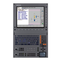
iTNC 530 E
HEIDENHAIN iTNC 530 E Manuals
Manuals and User Guides for HEIDENHAIN iTNC 530 E. We have
2
HEIDENHAIN iTNC 530 E manuals available for free PDF download: User Manual
HEIDENHAIN iTNC 530 E User Manual (689 pages)
Conversational Programming
Brand:
HEIDENHAIN
| Category:
Control Panel
| Size: 25 MB
Table of Contents
Table of Contents
13
Controls on the Visual Display Unit
2
Software Options
6
Table of Contents
29
Introduction
37
The Itnc
38
Programming: Heidenhain Conversational, Smart.nc and Iso Formats
38
Operating Panel
39
Screen Layout
39
Visual Display Unit
39
Modes of Operation
41
Manual Operation and Electronic Handwheel
41
Programming and Editing
42
Program Run, Full Sequence and Program Run, Single Block
43
General" Status Display
44
Status Displays
44
Additional Status Displays
45
D Touch Probes
49
Hr Electronic Handwheels
50
Manual Operation and Setup
51
Switch-On, Switch-Off
52
Moving the Machine Axes
55
To Traverse with the Machine Axis Direction Buttons
55
Incremental Jog Positioning
56
Traversing with the Hr 410 Electronic Handwheel
57
Hr 420 Electronic Handwheel
58
Positioning with Manual Data Input
62
Entering Values
64
Changing the Spindle Speed and Feed Rate
65
Datum Setting with Axis Keys
67
Datum Management with the Preset Table
68
Traversing the Reference Points in Tilted Axes
76
Datum Setting on Machines with Rotary Tables
77
Datum Setting on Machines with Spindle-Head Changing Systems
77
Setting the Datum in a Tilted Coordinate System
77
Limitations on Working with the Tilting Function
78
Position Display in a Tilted System
78
Activating Manual Tilting
79
Setting the Current Tool-Axis Direction as the Active Machining Direction (Fcl 2 Function)
80
Collision Monitoring in the Manual Operating Modes
81
Collision Monitoring in Automatic Operation
83
Positioning with Manual Data Input (MDI)
85
Protecting and Erasing Programs in $MDI
88
Position Encoders and Reference Marks
90
Reference System
90
Reference System on Milling Machines
91
Polar Coordinates
92
Absolute and Incremental Workpiece Positions
93
Setting the Datum
94
File Management
95
Data Backup
96
Working with the File Manager
97
Overview: Functions of the File Manager
98
Calling the File Manager
99
Selecting Drives, Directories and Files
100
Creating a New Directory (Only Possible on the Drive Tnc)
102
Copying a Single File
103
Choosing One of the Last Files Selected
105
Copying a Directory
105
Deleting a Directory
106
Deleting a File
106
Tagging Files
107
Renaming a File
108
Data Transfer to or from an External Data Medium
109
Copying Files into Another Directory
111
The Tnc in a Network
112
Usb Devices on the Tnc (Fcl 2 Function)
113
Creating and Writing Programs
114
Defining the Blank Form – Blk Form
114
Organization of an Nc Program in Heidenhain Conversational Format
114
Creating a New Part Program
115
Programming Tool Movements in Conversational Format
117
Actual Position Capture
119
Editing a Program
120
The Tnc Search Function
124
Generating a Graphic for an Existing Program
126
Functions of the 3-D Line Graphics
129
Highlighting Nc Blocks in the Graphics
131
Structuring Programs
132
Definition and Applications
132
Displaying the Program Structure Window / Changing the Active Window
132
Inserting a Structuring Block in the (Left) Program Window
132
Selecting Blocks in the Program Structure Window
132
Adding Comments
133
Entering a Comment in a Separate Block
133
Entering Comments During Programming
133
Inserting Comments after Program Entry
133
Functions for Editing of the Comment
134
Creating Text Files
135
Opening and Exiting Text Files
135
Editing Texts
136
Deleting and Inserting Characters, Words and Lines
137
Editing Text Blocks
138
Finding Text Sections
139
Integrated Pocket Calculator
140
Display Help
141
Displaying Error Messages
141
Show Error List
142
Window Contents
143
Pallet Management
144
Selecting a Pallet Table
146
Selecting a Pallet File
152
Setting up the Pallet File with the Entry Form
153
Sequence of Tool-Oriented Machining
157
Programming: Tools
161
Entering Tool-Related Data
162
Feed Rate F
162
Spindle Speed S
163
Tool Data
164
Requirements for Tool Compensation
164
Tool Length L
164
Tool Numbers and Tool Names
164
Delta Values for Lengths and Radii
165
Entering Tool Data into the Program
165
Tool Radius R
165
Entering Tool Data in Tables
166
Using an External Pc to Overwrite Individual Tool Data
171
Pocket Table for Tool Changer
172
Calling Tool Data
175
Tool Change
176
Tool Compensation
178
Tool Length Compensation
178
Tool Radius Compensation
179
Definition of a Normalized Vector
183
Permissible Tool Forms
184
Using Other Tools: Delta Values
184
D Compensation Without Tool Orientation
185
Face Milling: 3-D Compensation with and Without Tool Orientation
186
Peripheral Milling: 3-D Radius Compensation with Workpiece Orientation
188
Table for Workpiece Materials
191
Table for Cutting Data
192
Table for Tool Cutting Materials
192
Data Required for the Tool Table
193
Working with Automatic Speed / Feed Rate Calculation
194
Changing the Table Structure
195
Switching between Table and Form View
196
Configuration File Tnc.sys
197
Data Transfer from Cutting Data Tables
197
Programming: Programming Contours
199
Path Functions
200
Tool Movements
200
Miscellaneous Functions M
200
Programming with Q Parameters
200
Subprograms and Program Section Repeats
200
Important Positions for Approach and Departure
205
Overview: Types of Paths for Contour Approach and Departure
205
Approaching on a Straight Line Perpendicular to the First Contour Point: Appr Ln
208
Approaching on a Straight Line with Tangential Connection: Appr Lt
208
Overview of Path Functions
213
Straight Line L
214
Inserting a Chamfer Chf between Two Straight Lines
215
Corner Rounding Rnd
216
Circle Center CC
217
Circular Path C Around Circle Center CC
218
Circular Path Cr with Defined Radius
219
Circular Path Ct with Tangential Connection
220
Polar Coordinate Origin: Pole CC
226
Circular Path Cp Around Pole CC
227
Straight Line Lp
227
Circular Path Ctp with Tangential Connection
228
Helical Interpolation
229
Contour Programming
234
Graphics During Fk Programming
235
Converting Fk Programs into Heidenhain Conversational Format
236
Initiating the Fk Dialog
237
Free Programming of Straight Lines
238
Free Programming of Circular Arcs
238
Input Possibilities
239
Auxiliary Points
242
Relative Data
243
Opening a Dxf File
252
Basic Settings
253
Layer Settings
254
Datum Specifying
255
Contour Selection, Saving a Contour Program
257
Zoom Function
258
Programming: Miscellaneous Functions
259
Programming Machine-Referenced Coordinates: M91/M
262
Miscellaneous Functions for Coordinate Data
262
Activating the most Recently Entered Datum: M
264
Moving to Positions in a Non-Tilted Coordinate System with a Tilted Working Plane: M
264
Smoothing Corners: M
265
Insert Rounding Arc between Straight Lines: M
266
Machining Small Contour Steps: M
267
Machining Open Contours: M
269
Feed Rate Factor for Plunging Movements: M
270
Feed Rate for Circular Arcs: M109/M110/M
271
Feed Rate in Millimeters Per Spindle Revolution: M
271
Calculating the Radius-Compensated Path in Advance (Look Ahead): M
272
Superimposing Handwheel Positioning During Program Run: M
274
Retraction from the Contour in the Tool-Axis Direction: M
275
Suppressing Touch Probe Monitoring: M
276
Delete Basic Rotation: M
277
Delete Modal Program Information: M
277
Automatically Retract Tool from the Contour at an Nc Stop: M
278
Suppress Limit Switch Message: M
279
Miscellaneous Functions for Rotary Axes
280
Shorter-Path Traverse of Rotary Axes: M
281
Exact Stop at Corners with Nontangential Transitions: M
286
Selecting Tilting Axes: M
286
Programming: Cycles
291
Working with Cycles
292
Machine-Specific Cycles
292
Defining a Cycle Using Soft Keys
293
Defining a Cycle Using the Goto Function
293
Calling Cycles
295
Working with the Secondary Axes U/V/W
297
Point Tables
298
Creating a Point Table
298
Hiding Single Points from the Machining Process
299
Selecting a Point Table in the Program
300
Calling a Cycle in Connection with Point Tables
301
Centering (Cycle)
305
Drilling (Cycle)
307
Reaming (Cycle)
309
Boring (Cycle)
311
Universal Drilling (Cycle)
313
Back Boring (Cycle)
315
Universal Pecking (Cycle)
317
Bore Milling (Cycle)
320
Rigid Tapping Without a Floating Tap Holder New (Cycle)
324
Tapping with Chip Breaking (Cycle)
326
Fundamentals of Thread Milling
328
Thread Milling (Cycle)
330
Thread Drilling/Milling (Cycle)
336
Outside Thread Milling (Cycle)
344
Rectangular Pocket (Cycle)
354
Circular Pocket (Cycle)
359
Slot Milling (Cycle)
363
Circular Slot (Cycle)
368
Pocket Finishing (Cycle)
373
Stud Finishing (Cycle)
375
Circular Pocket Finishing (Cycle)
377
Circular Stud Finishing (Cycle)
379
Circular Slot (Oblong Hole) with Reciprocating Plunge-Cut (Cycle)
384
Circular Pattern (Cycle)
391
Linear Pattern (Cycle)
393
Sl Cycles
397
Overview of Sl Cycles
399
Contour Data (Cycle)
404
Pilot Drilling (Cycle)
405
Rough-Out (Cycle)
406
Floor Finishing (Cycle)
407
Side Finishing (Cycle)
408
Contour Train (Cycle)
409
Cylinder Surface (Cycle 27, Software Option)
411
Cylinder Surface Slot Milling (Cycle 28, Software Option)
413
Cylinder Surface Ridge Milling (Cycle 29, Software Option)
416
Sl Cycles with Contour Formula
431
Selecting a Program with Contour Definitions
432
Defining Contour Descriptions
433
Entering a Contour Formula
434
Contour Machining with Sl Cycles
437
Cycles for Multipass Milling
441
D Data (Cycle)
442
Multipass Milling (Cycle)
443
Ruled Surface (Cycle)
445
Face Milling (Cycle)
448
Datum Shift (Cycle)
457
Datum Shift with Datum Tables (Cycle)
458
Datum Setting (Cycle)
462
Mirror Image (Cycle)
463
Scaling Factor (Cycle)
466
Axis-Specific Scaling (Cycle)
467
Working Plane (Cycle 19, Software Option)
468
Special Cycles
476
Dwell Time (Cycle)
476
Program Call (Cycle)
477
Oriented Spindle Stop (Cycle)
478
Tolerance (Cycle 32, Software Option)
479
Programming: Special Functions
481
Define the Plane Function
484
Position Display
484
Reset the Plane Function
485
Abbreviations Used
497
Define Tcpm Function
506
Mode of Action of the Programmed Feed Rate
507
Interpretation of the Programmed Rotary Axis Coordinates
508
Reset Tcpm Function
510
Prerequisites for the Program to be Converted
512
Application Example
513
Programming: Subprograms and Program Section Repeats
515
Calling a Subprogram
517
Calling a Program Section Repeat
518
Label Lbl
518
Programming a Program Section Repeat
518
Calling any Program as a Subprogram
520
Nesting Depth
521
Subprogram Within a Subprogram
521
Types of Nesting
521
Repeating Program Section Repeats
522
Repeating a Subprogram
523
Programming: Q Parameters
531
Principle and Overview
532
Calling Q Parameter Functions
533
Programming Fundamental Operations
536
Trigonometric Functions
537
Programming Trigonometric Functions
538
Calculating Circles
539
Unconditional Jumps
540
Additional Functions
543
Fn14: Error: Displaying Error Messages
544
Fn15: Print: Output of Texts or Q Parameter Values
547
Fn16: F-Print: Formatted Output of Texts or Q Parameter Values
548
Fn18: Sys-Datum Read Read System Data
553
Fn19: Plc: Transferring Values to the Plc
559
Fn20: Wait For: Nc and Plc Synchronization
560
Fn 25: Preset: Setting a New Datum
561
Fn260Abopen: Opening a Freely Definable Table
562
Fn27: Tabwrite: Writing to a Freely Definable Table
562
Fn280Abread: Reading a Freely Definable Table
563
Entering Formulas
564
Entering Formulas Directly
564
Rules for Formulas
566
Programming Example
567
Preassigned Q Parameters
568
Values from the Plc: Q100 to Q
568
Active Tool Radius: Q
568
Tool Axis: Q
568
Spindle Status: Q
569
Coolant On/Off: Q
569
Overlap Factor: Q
569
Unit of Measurement for Dimensions in the Program: Q
569
Tool Length: Q
569
Coordinates after Probing During Program Run
570
Test Run and Program Run
581
Plan View
584
Overview of Display Modes
584
Projection in 3 Planes
585
D View
586
Magnifying Details
589
Repeating Graphic Simulation
590
Measuring the Machining Time
591
Functions for Program Display
592
Test Run
593
Program Run
596
Run a Part Program
596
Interrupting Machining
597
Moving the Machine Axes During an Interruption
598
Resuming Program Run after an Interruption
599
MID-Program Startup (Block Scan)
600
Returning to the Contour
602
Automatic Program Start
603
Erasing the "/" Character
604
Optional Block Skip
604
MOD Functions
607
Mod Function
608
Changing the Settings
608
Exiting the Mod Functions
608
Selecting the Mod Functions
608
Overview of Mod Functions
609
Code Numbers
611
Loading Service Packs
612
Setting the Data Interfaces
613
Setting the Rs-232 Interface
613
Setting the Rs-422 Interface
613
Setting the Operating Mode of the External Device
613
Setting the Baud Rate
613
Software for Data Transfer
615
Introduction
617
Ethernet Interface
617
Connection Possibilities
617
Connecting the Itnc Directly with a Windows Pc
618
Configuring the Tnc
620
Configuring Pgm Mgt
625
Changing the Pgm Mgt Setting
625
Dependent Files
626
Rotate the Entire Image
630
Position Display Types
631
Unit of Measurement
632
Datum Display
635
Find and Enter the Maximum Traverse
635
Displaying Help Files
637
Selecting Help Files
637
External Access
640
Tables and Overviews
641
General User Parameters
642
Input Possibilities for Machine Parameters
642
Selecting General User Parameters
642
Compatibility
655
Non-Heidenhain Devices
657
Ethernet Interface Rj45 Socket
658
Rs-422/V.11 Interface
658
Technical Information
659
Exchanging the Buffer Battery
666
Itnc 530 with Windows 2000 (Option)
667
General Information
668
End User License Agreement (Eula) for Windows
668
Specifications
669
Logging on as a Tnc User
670
Logging on to Windows
670
Logging on as a Local Administrator
671
Switching off the Itnc
672
Logging a User off
672
Exiting the Itnc Application
673
Shutting down Windows
674
Network Settings
675
Adjusting the Network Settings
675
Controlling Access
676
The Itnc Drive
677
Data Transfer to the Itnc
678
Visual Display Unit
683
Overview Tables
685
Status Displays
687
Miscellaneous Functions
687
D Touch Probes
689
Example
689
Advertisement
HEIDENHAIN iTNC 530 E User Manual (514 pages)
Cycle Programming
Brand:
HEIDENHAIN
| Category:
Control Panel
| Size: 10 MB
Table of Contents
About this Manual
3
TNC Model, Software and Features
4
Software Options
6
Feature Content Level (Upgrade Functions)
8
New Cycle Functions of Software 340 49X-02
10
Table of Contents
19
Fundamentals / Overviews
21
Fixed Cycles: Drilling
23
Fixed Cycles: Tapping / Thread Milling
24
Fixed Cycles: Pattern Definitions
26
Fixed Cycles: Cylindrical Surface
28
Fixed Cycles: Multipass Milling
30
Cycles: Coordinate Transformations
31
Cycles: Special Functions
33
Touch Probe Cycles: Special Functions
40
Fundamentals / Overviews
43
Available Cycle Groups
45
Overview of Fixed Cycles
45
Overview of Touch Probe Cycles
46
Using Fixed Cycles
47
Machine-Specific Cycles
48
Working with Fixed Cycles
48
Defining a Cycle Using Soft Keys
49
Defining a Cycle Using the GOTO Function
49
Example NC Blocks
49
Calling a Cycle with CYCL CALL
50
Calling a Cycle with CYCL CALL PAT
50
Calling Cycles
50
Calling a Cycle with CYCL CALL POS
51
Calling a Cycle with M99/89
51
Working with the Secondary Axes U/V/W
52
Program Defaults for Cycles
53
Entering GLOBAL DEF
54
Using GLOBAL DEF Information
54
Global Data for Drilling Operations
55
Global Data Valid Everywhere
55
Global Data for Milling Operations with Pocket Cycles 25X
56
Global Data for Positioning Behavior
56
Global Data for Probing Functions
57
Application
58
Pattern Definition PATTERN DEF
58
Entering PATTERN DEF
59
Using PATTERN DEF
59
Defining Individual Machining Positions
60
Defining a Single Row
61
Defining a Single Pattern
62
Defining Individual Frames
63
Defining a Full Circle
64
Defining a Circular Arc
65
Creating a Point Table
66
Function
66
Point Tables
66
Hiding Single Points from the Machining Process
67
Selecting a Point Table in the Program
68
Calling a Cycle in Connection with Point Tables
69
Fixed Cycles: Drilling
71
Basics
72
Overview
72
Centering Diameter or Centering Depth
73
Cycle Parameters
74
Cycle Run
75
Drilling
75
Setup Clearance
76
Reaming
77
Setup Clearance
78
Boring
79
Setup Clearance
82
Universal Drilling
83
Back Boring
87
Setup Clearance
90
Universal Pecking
91
Bore Milling
95
Single-Fluted Deep-Hole Drilling
98
Programming Examples
101
Example: Using Drilling Cycles in Connection with PATTERN DEF
103
Fixed Cycles: Tapping / Thread Milling
105
Tapping New
107
Rigid Tapping
109
Retracting after a Program Interruption
111
Tapping with Chip Breaking
112
Fundamentals of Thread Milling
115
Prerequisites
115
Thread Milling
117
Thread Milling/Countersinking
120
Thread Drilling/Milling
124
Helical Thread Drilling/Milling
128
Outside Thread Milling
132
Fixed Cycles: Pocket Milling / Stud Milling /Slot Milling
139
Rectangular Pocket
141
Circular Pocket
146
Slot Milling
150
Circular Slot
155
Rectangular Stud
160
Circular Stud
164
Fixed Cycles: Pattern Definitions
171
Circular Pattern
173
Linear Pattern
176
Example: Circular Hole Patterns
178
Fixed Cycles: Contour Pocket, Contour Trains
181
Characteristics of the Subprograms
182
SL Cycles
182
Characteristics of the Fixed Cycles
183
Contour Geometry
185
Overlapping Contours
186
Subprograms: Overlapping Pockets
187
Area of Inclusion
188
Area of Exclusion
189
Contour Data
190
Pilot Drilling
192
Rough-Out
194
Floor Finishing
198
Side Finishing
199
Contour Train
201
Trochoidal Slot
205
Finishing with Closed Slots
206
Roughing with Closed Slots
206
Roughing with Open Slots
206
Example: Roughing-Out and Fine-Roughing a Pocket
211
Example: Contour Train
216
Fixed Cycles: Cylindrical Surface
219
Overview of Cylindrical Surface Cycles
220
Cylinder Surface
221
Example: Cylinder Surface with Cycle 27
233
Example: Cylinder Surface with Cycle 28
235
Fixed Cycles: Contour Pocket with Contour Formula
237
SL Cycles with Complex Contour Formula
238
Properties of the Subcontours
239
Selecting a Program with Contour Definitions
240
Defining Contour Descriptions
241
Entering a Complex Contour Formula
242
Contour Machining with Sl Cycles
245
Roughing/Finishing Superimposed Contours with Contour Formula
246
Fixed Cycles: Multipass Milling
253
Run 3-D Data
255
Multipass Milling
257
Ruled Surface
259
Face Milling
263
Example: Multipass Milling
268
Datum Shift
274
DATUM Shift with Datum
275
Editing a Pocket Table in a Program Run Operating Mode
279
Transferring the Actual Values into the Datum Table
279
Configuring the Datum Table
280
To Exit a Datum Table
280
Datum Setting
281
Mirror Image
282
Rotation
284
Scaling Factor
286
Axis-Specific Scaling Factor
288
Working Plane
290
Positioning the Axes of Rotation
293
Automatic Positioning of Rotary Axes
294
Position Display in the Tilted System
295
Positioning in a Tilted Coordinate System
295
Workspace Monitoring
295
Combining Coordinate Transformation Cycles
296
Example: Coordinate Transformation Cycles
299
Cycles: Special Functions
301
Dwell Time
303
Program Call
304
Cycle Function
306
Oriented Spindle Stop
306
Tolerance
307
Influences of the Geometry Definition in the CAM System
308
Cycle Parameters
310
Using Touch Probe Cycles
311
General Information about Touch Probe Cycles
312
Cycles in the Manual and El. Handwheel Modes
313
Touch Probe Cycles for Automatic Operation
313
Before You Start Working with Touch Probe Cycles
315
Maximum Traverse to Touch Point: MP6130
315
Orient the Infrared Touch Probe to the Programmed Probe Direction: Mp
315
Safety Clearance to Touch Point: MP6140
315
Confidence Interval for Multiple Measurement: Mp
316
Consider a Basic Rotation in the Manual Operation Mode: Mp
316
Multiple Measurement: Mp
316
Kinematicsopt, Permissible Deviation of the Calibration Ball Radius: Mp
317
Kinematicsopt: Tolerance Limit in Optimization Mode: Mp
317
Touch Trigger Probe, Probing Feed Rate: MP6120
317
Touch Trigger Probe, Rapid Traverse for Positioning: Mp
317
Executing Touch Probe Cycles
318
Basic Rotation
322
Basic Rotation
331
Compensation Via Rotary Axis
331
Set Basic Rotation
335
Example: Determining a Basic Rotation from Two Holes
340
Touch Probe Cycles: Automatic Datum Setting
341
Measurement Results in Q Parameters
344
Saving the Calculated Datum
344
Slot Center Ref Pt
345
Ridge Center Ref Pt
349
Datum from Outside of Corner
368
Classification of Results
399
Tolerance Monitoring
400
Tool Compensation
400
Tool Monitoring
400
Reference System for Measurement Results
401
Tool Breakage Monitoring
401
Ref. Plane
402
Polar Reference Plane
403
Measure Angle
405
Measure Hole
408
Meas. Circle Outside
412
Meas. Rectan. Outside
420
Measure Inside Width
424
Measure Ridge Width
427
Measure Coordinate
430
Meas. Bolt Hole Circ.
433
Measure Plane
437
Touch Probe Cycles: Special Functions
445
Calibrate Ts
447
Calibrate Ts Length
448
Measuring
449
Cycle Run
451
Measuring in 3-D
451
Cycle Parameters
452
Measure Axis Shift
453
Fast Probing
456
Touch Probe Cycles: Automatic Kinematics Measurement
461
Kinematic Measurement with TS Touch Probes
462
Save Kinematics
464
Log Function
465
Measure Kinematics
466
Positioning Direction
468
Example Calculation of Measuring Positions for an a Axis
469
Machines with Hirth-Coupled Axes
469
Choice of Number of Measuring Points
470
Choice of the Calibration Sphere Position on the Machine Table
470
Notes on the Accuracy
471
Fine Optimization over the Entire Range of Traverse
472
Inspecting the Machine Accuracy
472
Notes on Various Calibration Methods
472
Optimization of a Specific Rotary Axis Position
472
Backlash
473
Position and Angle Optimization Mode Q406 = 2
478
Position Optimization Mode Q406 = 1
478
Test Mode Q406 = 0
478
Various Modes (Q406)
478
Dispersion (Standard Deviation)
480
Error Outputs
480
Evaluation of Measuring Points
480
Notes on Log Data
480
Measurement Uncertainty of Angles
481
Preset Compensation
482
Adjustment of Tool Changer Heads
487
Example: Adjusting a Tool Changer Head
488
Drift Compensation
489
Touch Probe Cycles: Automatic Tool Measurement
493
Setting the Machine Parameters
495
Differences between Cycles 31 to 33 and Cycles 481 to 483
495
Entries in the Tool Table TOOL.T
497
Display of the Measurement Results
498
Calibrating the TT
499
Calibrating the Wireless
500
Measuring the Tool Length
501
Cycle for Measuring a Tool During Rotation
501
Cycle for Measuring a Tool During Standstill (E.g. for Drills)
501
Cycle for Measuring Individual Teeth
501
Measuring the Tool Radius
503
Measuring Tool Length and Radius
505
Fixed Cycles
509
Advertisement
Related Products
HEIDENHAIN ITNC 530 - PILOT SMART NC
HEIDENHAIN ITNC 530 - CYCLE PROGRAMMING
HEIDENHAIN ITNC 530 - CONVERSATIONAL PROGRAMMING
HEIDENHAIN iTNC 530 HSCI
HEIDENHAIN IK 5000 QUADRA-CHEK
HEIDENHAIN QUADRA-CHEK IK 559 Series
HEIDENHAIN ID 344980-01
HEIDENHAIN ID 344980-02
HEIDENHAIN ID 331143-04
HEIDENHAIN IOB 49
HEIDENHAIN Categories
Media Converter
Measuring Instruments
Industrial Equipment
Control Systems
Control Unit
More HEIDENHAIN Manuals
Login
Sign In
OR
Sign in with Facebook
Sign in with Google
Upload manual
Upload from disk
Upload from URL