Sign In
Upload
Manuals
Brands
ge Manuals
Clock
Reason RT430
ge Reason RT430 Manuals
Manuals and User Guides for ge Reason RT430. We have
2
ge Reason RT430 manuals available for free PDF download: Technical Manual
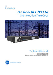
GE Reason RT430 Technical Manual (101 pages)
GNSS Precision-Time Clock
Brand:
GE
| Category:
Control Unit
| Size: 3.14 MB
Table of Contents
3
Table of Contents
7
Table of Figures
9
List of Tables
11
Chapter 1: Introduction
11
Foreword
11
Target Audience
11
Accronyms and Abbreviations
13
Product Scope
13
Available Models
14
Key Features
15
Gnss
15
Ptp / Sntp / Ntp
15
Parallel Redundancy Protocol (PRP)
15
Stationary Mode
16
Time Sync Flexibility
16
Environmental Robustness
17
Functional Overview
17
Standards Compliance
17
Figure 1: Functional Overview of RT430/434
18
Chapter 2: Safety Information
18
Health and Safety
18
Symbols
19
Installation, Commissioning and Servicing
19
Lifting Hazards
19
Electrical Hazards
21
Fusing Requirements
21
Equipment Connections
22
Pre-Energization Checklist
23
Peripheral Circuitry
23
Upgrading/Servicing
23
Decommissioning and Disposal
24
Chapter 3: Hardware Design
24
Front View
24
Rear View
24
Figure 2: Front View of RT430
24
Figure 3: Front View of RT434
25
Network Ports
25
Power Supply
25
Figure 4: Rear View of RT430
25
Figure 5: Rear View of RT434
26
Chapter 4: Installation
26
Unpacking
26
Normal Use of the Equipment
26
External Indications
26
Figure 6: Location of Serial Number, Part Number and Outputs Description
27
Mounting
27
Power Supply
27
Figure 7: Pre-Insulated Tubular Pin Terminals
27
Figure 8: Supply Connector Assembly
27
Figure 9: RT430/RT434 Power Connection
28
Grounding (Earthing)
28
GNSS Antenna Terminal
28
Figure 10: RT430/434 Grounding Strap
28
Figure 11: GNSS Antenna Connector
29
Figure 12: Recommended Position for Installing the GNSS Antenna
29
Figure 13: Recommended Position GNSS Antenna Conduit Installation
30
TTL Electrical Outputs
30
Open-Collector Electrical Outputs
30
Figure 14: TTL Electrical Outputs
31
Optical Outputs
31
Figure 15: Open Collector Electrical Outputs
31
Figure 16: Connection Diagram of the Open-Collector Electrical Outputs
32
Amplitude Modulated Output
32
Serial Port (RS232, RS422/485)
32
Figure 17: Optical Outputs
32
Figure 18: Amplitude Modulated Output
32
Figure 19: Serial Port RS232 and RS422/485
32
Table 1: Serial Port Pinout
33
Dry-Contact Relay
33
Event Input
33
Figure 20: Dry-Contact Relay
34
Euro Type Connections
34
Ethernet Communication
34
Figure 21: Event Input
34
Figure 22: Euro Type Label for Connections
35
Factory Default Settings
35
Figure 23: Electrical Communication Interface Via Ethernet Network
35
Table 2: Ethernet Port 1 Default Settings
35
Table 3: Ethernet Port 2 Default Settings
35
Table 4: Ethernet Port 3 Default Settings (RT434)
35
Table 5: Ethernet Port 4 Default Settings (RT434)
36
Equipment Access
36
Network Port and Communication Protocols
36
Powering Up
36
Table 6: Gateway and DNS Server Default Settings
36
Table 7: Gateway and DNS Server
37
Preventive Maintenance Actions
37
Preventive Actions
40
Chapter 5: Operation
40
Local Interface (HMI)
40
Figure 24: Local Interface From RT430 and RT434
40
Figure 25: Navigating the Rt430'S Local Monitoring Display
41
Web Interface (Remote Access)
41
Web Interface Language
41
Figure 26: RT430 Web Interface
41
Figure 27: Languages Available in the Web Interface
42
Monitoring Menus - Web Interface
42
Status
42
Figure 28: Section to Monitor the Status of the Unit in the Web Interface
43
General Information
43
Event Log
43
Figure 29: Section to Visualize General Information of the System
44
Figure 30: Section of Web Interface to Monitor Timestamps of Event Input
45
Chapter 6: Configuration
45
Web Interface
45
User Name and Password
45
Sending Configuration
45
Table 8: Factory Default Username and Password
46
Ethernet
46
PRP (Only in RT430)
46
Figure 31: Section to Configure Network Parameters of the Unit
47
Ethernet Ports
47
Default Gateway
47
DNS Server
47
Ethernet - Configuration Summary
47
Figure 32: Enabling the PRP Redundancy
48
Time Settings
48
Time Parameters
48
Figure 33: Section to Configure Time Parameters
48
Table 9: Summary of Configurable Network Parameters
49
Time Settings - Configuration Summary
49
Table 10: Summary of Configurable Time Parameters
50
Time Signals
50
Outputs
50
Figure 34: Section to Configure Time Signals Applied in the Outputs
51
Serial Datagram
52
Customizable Datagrams
52
Table 11: Customizable Datagram Special Characters
53
Time Signals - Configuration Summary
53
Table 12: Summary of All Configurable Parameters for Outputs
55
PTP Configuration
55
Profile
55
Figure 35: Section to Configure PTP Parameters
56
Figure 36: Characteristics From PTP Power Profile IEEE C37.238:2011
56
Figure 37: Characteristics From PTP Power Profile IEEE C37.238:2011
57
Comparison Between PTP Power Profiles
57
Domain Number
57
Network Protocol
57
Operation Mode
57
Table 13: Comparison Between PTP Power Profiles
58
Delay Mechanism
58
Grandmaster Priority
58
PTP Messages
58
PTP - Configuration Summary
59
Table 14: Summary of Configurable PTP Parameters
60
Setup
60
Figure 38: Setup Section in Web Interface
61
Configuration Management
61
Demo Mode
61
Password Configuration
61
Reset Satellites Almanac
61
Stationary Mode
62
Figure 39: Manual Time Setting - Only Available in Demo Mode
62
Log Files
62
Reboot System
63
Chapter 7: Maintenance
63
Time Synchronization Failure (Locked Signaling)
63
Locked Indicator (HMI)
64
Remote Monitoring (Web Interface)
64
Dry-Contact Relay (Locked)
64
IRIG-B Signal
64
PTP Protocol
64
NTP Protocol
64
SNTP Protocol
65
Equipment Upgrade - Key Change
65
Figure 40: Section to Update Firmware
65
Figure 41: Section to Equipment Upgrade - Key Change
66
Cleaning Instructions
66
Equipment Return
67
Chapter 8: Technical Specification
67
Power Supply
67
GNSS Antenna
67
GNSS Antenna Receiver
67
Table 15: Power Supply Specifications
67
Table 16: GNSS Antenna Input Specifications for Temporal Synchronization
68
GNSS Antenna Type
68
Antenna Cable
68
Table 17: GNSS Antenna Specifications
68
Table 18: Antenna Cable Specifications
69
Surge Arrester
69
Internal Oscillator
69
Table 19: Surge Arrester Specifications
69
Table 20: Internal Oscillator Specifications
70
Outputs
70
Connectors
70
Figure 42: Rear Panel Connectors of RT430 (Top) and RT434 (Bottom)
70
Table 21: RT430/434 Rear Panel Connectors
71
TTL Electrical Outputs
71
Open Collector Electrical Outputs
71
Table 22: Electrical Outputs Specifications
71
Table 23: Open Collector Outputs Specifications
72
Optical Outputs
72
Amplitude Modulated Output
72
Table 24: Optical Outputs Specifications
72
Table 25: Amplitude Modulated Output
73
Serial Port (RS232, RS422/485)
73
Dry-Contact Relay
73
Event Input
73
Table 26: RS232 or RS422/485 Serial Port Specifications
73
Table 27: Dry-Contact Relay Specification
73
Table 28: Event Input Specification
74
Precision Time Protocol PTP (IEEE 1588)
74
Ethernet Ports
74
Table 29: PTP Time Synchronization Protocol Specifications
74
Table 30: Ethernet Ports Specification
75
Environment
75
Type Test
75
Table 31: Environment Specification
75
Table 32: Enclosure Protection IEC 60529
75
Table 33: EMC Tests Were Performed According to IEC 60255-26 Referring to the Following Standards
77
Table 34: Safety Tests
77
Table 35: Environmental Tests
78
Dimensions, Weight
78
Figure 43: RT430/434 Dimensions
78
Table 36: Dimensions and Weight Specification RT430/434
79
Chapter 9: Ordering Options
80
RT430 GNSS Cortec
81
RT434 GNSS Cortec
83
Appendix A - IRIG-B Standard Summary
83
Table 37: IRIG-B Standard Summary
83
Chapter 10
88
Appendix B - PTP Standard Concepts (IEEE1588)
88
Description
88
Definitions According to IEEE 1588 Standard
89
Hierarchical Topology
89
Multicast and Unicast Networks
90
PTP Synchronization
91
Network Protocols
91
Clock Operation Mode
91
Delay Measurement Mechanism
92
Master, Slave and Grandmaster Clocks
92
PTP Messages
93
Appendix C - Serial Datagrams
93
ACEB Datagrams
93
NEMEA GPZDA Datagram
93
Table 38: ACEB Datagram Information
94
Meinberg Datagram
94
Table 39: GPZDA Datagram Time Information
94
Table 40: GPZDA Datagram Line Feed and Carriage Return Information
94
Table 41: GPZDA Datagram Checksum Information
95
Table 42: Meinberg Datagram Time Information
95
Table 43: Meinberg Datagram Beginning and End Information
95
Table 44: Meinberg Datagram Locked State Information
96
Appendix D - Antenna Delay Compensation
96
Signal Attenuation
96
Propagation Delay
96
Table 45: Antenna Cables Attenuation @ 1500 Mhz (±1 Db)
97
Table 46: Attenuation of Antenna Cables
98
Appendix E - Application Examples
98
Application Example 1: Traditional and Modern Time Sync
98
Application Example 2: System Wide Grandmaster Clock
98
Figure 44: Traditional X Modern Time Synchronization
99
Application Example 3: Synchrophasor, TWFL and Process Bus Applications
99
Figure 45: System Wide Grandmaster Clock
99
Figure 46: Synchrophasor Devices Synced By RT430/434
100
Application Example 4: IEEE 1588 in a PRP Network
100
Figure 47: TWFL Application Using RT430/434 for Time Sync
100
Figure 48: Process Bus Application Using PTP Via the Station Bus Network
101
Application Example 5: Time Sync Expansion Using RT411 and RT412
101
Figure 49: Process Bus Application Using PTP Via the Station Bus Network
101
Figure 50: Time Sync Expansion Using RT411 and RT412
Advertisement
ge Reason RT430 Technical Manual (102 pages)
a clock referenced to GPS and GLONASS satellites
Brand:
ge
| Category:
Clock
| Size: 3.66 MB
Table of Contents
1
Technical Manual
2
Table of Contents
7
Preface
8
Acronyms and Abbreviations
10
Safety Section
10
Chapter Overview
10
Health and Safety
10
Symbols
11
Installation, Commissioning and Servicing
11
Lifting Hazards
11
Electrical Hazards
13
Fusing Requirements
13
Equipment Connections
14
Pre-Energisation Checklist
14
Peripheral Circuitry
15
Upgrading/Servicing
15
Decommissioning and Disposal
15
Standards Compliance
16
EMC Compliance
16
Product Safety
16
Installation Category
16
Protective Class
16
Environment
16
R&TTE Compliance
17
Description
17
Introduction
18
Foreword
18
Key Features
19
Available Models
19
Network Ports
19
Power Supply
20
Front and Rear Views
21
Technical Specifications
21
Power Supply
21
Gps Antenna Input
22
Gps Antenna
22
Antenna Cable
23
Internal Oscillator
23
Ttl Level Electrical Outputs (Irig-B004/Ppx/Dcf77)
24
Open Collector Electrical Outputs
24
Optical Outputs
24
Amplitude Modulated Outputs
25
Serial Port (Rs232, Rs422/485)
25
Dry-Contact Relay (Locked)
25
Event Input
26
Precision Time Protocol Ptp (Ieee 1588)
26
Ethernet Ports
26
Environment
28
Dimensions, Weight
29
Installation
29
Unpacking
29
Normal Use of the Equipment
29
External Indications
30
Environment
30
Mounting
30
Connectors
31
Power Supply
32
Ac Power Connection
32
DC Power Connection
33
Earthing (Grounding)
33
Powering Up
34
Gps Antenna Terminal
36
Ttl Electrical Outputs
36
Open-Collector Electrical Outputs
37
Optical Outputs
38
Amplitude Modulated Outputs
38
Serial Port (Rs232, Rs422/485)
40
Dry-Contact Relay (Locked)
40
Event Input
41
Type Test
45
Communication
45
Factory Default Settings
46
Network Port and Communication Protocols
46
Direct Communication
48
Communication Via Ethernet Network
49
Equipment Access
50
Configuration
50
Web Interface
50
Network Parameters
51
Ethernet 1/2
51
Default Gateway
52
Dns Server
52
Sending Configuration
52
Configuration Summary
53
Time Features
54
Time Settings
54
Sending Configuration
55
Configuration Summary
55
Synchronism Outputs
56
Outputs
57
Serial Datagram
57
Customizable Datagrams
59
Sending Configuration
59
Configuration Summary
62
Ptp Configuration
62
Profile
63
Domain Number
63
Network Protocol
63
Operation Mode
63
Delay Mechanism
64
Master and Slave Clocks
64
Ptp Messages
64
Sending Configuration
65
Configuration Summary
67
Configurations Control
67
Configuration Management
68
Password Configuration
69
Operation
69
Local Access (Ihm)
69
State Indicators
69
Display Monitoring
70
Remote Access (Interface Web)
70
Monitoring Equipment Status
71
General Information
72
Events Input
74
Maintenance
74
Synchronism Failure (Locked Signaling)
74
Locked Indicator (Ihm)
74
Remote Monitoring (Web Interface)
74
Dry-Contact Relay (Locked)
75
Irig-B Signal
75
Ptp Protocol
75
Ntp Protocol
75
Sntp Protocol
75
Firmware Update
76
Equipment Key Change
78
Cleaning Instructions
78
Equipment Return
78
Instructions for Equipment Repair/Service for Service Personnel
80
Appendix A - Cortec
82
Appendix B -Irig-B Standard Summary
87
Appendix C - Ptp Standard Concepts (Ieee1588)
93
Appendix D - Serial Datagrams
Share and save
Advertisement
Related Products
GE Reason RT434
GE Reason RT411
GE Alpha RT 32551
GE Hart Druck RTX 1000H Series
GE RTT
GE Reason RT412
GE RB525DPCT - 30" Electric Ran
GE Digital Radiant Cooktop
GE RCBS526
GE RCB757
ge Categories
Refrigerator
Ranges
Microwave Oven
Air Conditioner
Dishwasher
More ge Manuals
Login
Sign In
OR
Sign in with Facebook
Sign in with Google
Upload manual
Upload from disk
Upload from URL