Sign In
Upload
Manuals
Brands
Enterasys Manuals
Chassis
S Series
Enterasys S Series Manuals
Manuals and User Guides for Enterasys S Series. We have
6
Enterasys S Series manuals available for free PDF download: Hardware Installation Manual, Upgrade Installation Manual
Enterasys S Series Hardware Installation Manual (96 pages)
Stand Alone Switch
Brand:
Enterasys
| Category:
Switch
| Size: 4 MB
Table of Contents
Table of Contents
13
About this Guide
17
How to Use this Guide
17
Who Should Use this Guide
17
Related Documents
18
Typographical Conventions
19
Getting Help
20
Chapter 1: Introduction
21
Ssa-T8028-0652
21
SSA-T8028-0652 I/O Port Panel
21
System Leds
21
Ssa-G8018-0652
22
AC Power Supplies
22
Fans
22
SSA-G8018-0652 I/O Port Panel
22
Micro-USB Port
23
Management
23
Virtual Switch Bonding
23
Required Tools
25
Installation Site Requirements
26
Unpacking the SSA Switch
26
Mounting the SSA Switch
26
Contents of SSA Switch
26
SSA Switch Rack Configurations
27
Power Supply Air Flow and Switch Fan Module Air Flow
28
Switch Fan Module Air Flow Direction
28
Power Supply Air Flow Based on Model Number
28
Reversing the Fan Module Air Flow
29
Removing the Fan Module
29
Reversing the Fan Unit
29
Removing the Switch Fan Module
29
Reinstall the Fan Module
30
Rack Mount Ear Positioning
30
Reversing the Fan Module Air Flow
30
Flush-Mount Power Supply Facing Front Configuration
31
Flush Mount Power Supply Front Configuration
31
MID-Mount I/O Ports Facing Front Configuration
32
MID-Mount Power Supply Facing Front Configuration
32
Securing the SSA Switch to the Rack
33
MID-Mount Power Supply Front Configuration
33
Securing the SSA Switch to the Rack in a Flush Mount Configuration
34
Flat Surface Installation
35
Unpacking the Power Supplies
35
Securing the SSA Switch to the Rack in a MID-Mount Configuration
35
Installing the Power Supplies
36
Installing a Power Supply
36
Contents of SSA Power Supply Carton
36
Powering up the SSA Switch
37
Removing the Power Supply Bay Coverplate
37
Installing the Power Cord Retention Clip Assembly
38
Connecting to the Network
38
Installing the Power Cord Clip Assembly in the Power Supply
38
Connecting Category 6 UTP Ethernet Cables to the BASE-T Ports
39
Connecting Pluggable Transceivers to the SFP and SFP+ Ports
39
Preparation
40
Installing the Pluggable Transceiver
40
Removing the Pluggable Transceiver
40
SSA Switch Ground Receptacle
40
Connecting Two SSA Chassis for Virtual Switch Bonding
41
Connecting to the COM Port for Local Management
41
What Is Needed
41
Connecting to a PC or Laptop
42
Connecting to a VT Series Terminal
42
Adapter Wiring and Signal Assignments
43
Completing the Installation
44
Chapter 3: Troubleshooting
47
Leds
47
Port Leds
47
RJ45 Port Leds
47
Troubleshooting Checklist
47
SFP and SFP+ Port LEDS
48
Port Leds
48
System Leds
49
SSA System Leds
49
CPU LED in Virtual Switch Bonding (VSB) Configuration
50
Power Supply LED
51
Troubleshooting Checklist
51
Power Supply LED Status Definitions
51
Replacing the SSA Fan Module
52
Removing the Fan Module
53
Removing a Power Supply
54
Removing the Power Supply
54
Using the OFFLINE/RESET Button
55
Recommended Shutdown Procedure Using OFFLINE/RESET Button
55
Last Resort Shutdown Procedure Using OFFLINE/RESET Button
55
OFFLINE/RESET Button
55
Appendix A: Specifications
57
SSA Switch Specifications
57
SSA Switch Ports
57
Pluggable Transceiver Specifications
58
COM Port Pinout Assignments
58
COM Port Pin Assignments
58
Regulatory Compliance
59
Compliance Standards
59
Appendix B: Clearing the Persistent Storage or System Password
61
Clearing Persistent Storage or Password Using the Boot Loader Method
61
Clearing System Storage or Password Using the Dip Switch Method
62
Required Tools
63
About the Mode Switches
63
Setting the Mode Switches
64
Mode Switch Location
64
Required Tools
65
Contents of Mounting Kit
66
Installation Site Requirements
66
Contents of SSA-FB-MOUNTKIT
66
Required Order of Installation
67
Removing the Rack Mount Ears from the SSA Switch
67
Installing the Adapter Plates
67
Removing the SSA Switch Rack Mount Ears
67
Installing the Adapter Plates
68
4-Post Rack Mount Installation
69
Four Post Rack Supported Configurations
69
Rack Mount Rail with Attached Extension Assembly Installation
70
Installing the Rack Mount Rail with Extension Assemblies
70
Chassis to Rail Assembly Installation
71
Installing the Chassis on to the Rack Mount Rail Assembly
71
2-Post Rack Mount Installation
72
Two Post Rack Supported Configurations
72
Pre-Installation Tasks
73
Rack Mount Rail Assembly Extension Removal
73
MID-Bracket to Rail Assembly
73
Removing the Extension from the Rack Mount Rail Assembly
73
Securing MID-Bracket to Rail 3 Inch Flush Mount
74
Securing MID-Bracket to Rail 7.25 Inch Flush Mount
75
Securing MID-Bracket to Rail 7.25 Inch MID Mount
76
Securing the Rail Assembly for a 2-Post Flush Mount Configuration
77
Securing a Flush Mount Rail Assembly
77
Securing the Rail Assembly for a 2-Post MID-Mount Configuration
78
Securing MID-Mount Rail Assembly
78
Securing the SSA Switch to the Rack
79
Required Tools
81
Contents of SSA-WALL-MOUNT Kit
81
Installation Site Requirements
82
Preparing the Installation Site
82
Hollow Wall Construction
82
Toggle Bolts
83
Reusable Anchors
83
Pan Head Steel Machine Screws
83
Concrete or Masonry Wall Construction
83
Concrete Screws
84
Concrete Inserts
84
Mounting the SSA Chassis on a Wall
84
Securing the Wall Mounting Bracket to a Wall
85
Opening the Gate
86
Mounting Bracket Gate in the Open Position
87
Installing the SSA in the Mounting Bracket
88
Closing the Gate
89
Securing the SSA Chassis to the Mounting Bracket
90
Appendix E: Environmental Guidelines
91
Temperature and Humidity Guidelines
91
Operating Temperatures
91
Inlet Air Temperature Measurement
91
Cooling Air
91
Power Conditioning
91
Airflow Concerns for Closed Racks
92
Closed Rack Ideal Configuration
92
Airflow Concerns for Open Racks
93
Open Rack Ideal Configuration
93
Non-Ideal Open Rack Configuration
94
Mitigated Non-Ideal Open Rack Configuration
94
Dust Mitigation and Prevention
95
Another Mitigated Non-Ideal Open Rack Configuration
95
Airborne Chemicals and Prevention
96
Airborne Dust Specification for Enterasys Equipment - Airborne Dust Maximum Values
96
Advertisement
Enterasys S Series Hardware Installation Manual (76 pages)
Brand:
Enterasys
| Category:
Chassis
| Size: 10 MB
Table of Contents
Table of Contents
13
About this Guide
17
Who Should Use this Guide
17
How to Use this Guide
17
Related Documents
18
Typographical Conventions
18
Getting Help
19
Chapter 1: Introduction
21
Overview
21
S4 Chassis (S4-Chassis)
22
S4 Chassis with Four Bay Poe Subsystem (S4-Chassis-POE4)
23
Features
24
AC Power Supplies
24
Models
24
Redundancy
24
S-Series Modules
24
Auto-Ranging Input Voltage and Frequency
25
DC Power Supplies
25
Hot Swapping
25
Operating Status
25
Power over Ethernet (Poe)
26
RJ45 COM Ports
26
Standalone or Rack Mountable Chassis
26
The S-FAN Chassis Cooling System
26
USB Ports
26
Chapter 2: Installation Requirements and Guidelines
27
Site Guidelines
27
Location Guidelines
27
Rack Mounting Guidelines
27
AC Power Supply Guidelines
28
Temperature Guidelines
28
Precautions
28
Chapter 3 : Chassis Setup
30
Required Tools
30
Unpacking the S4 Chassis
30
Accessories that Ship with the S-Series Chassis
30
Installing the S4 Chassis
31
Order of Installation
31
Installing Rubber Feet
32
Installing the MID-Mount Brackets
32
Attaching the MID-Mount Brackets to the Sides of the Chassis
32
Rack Mounting the S4 Chassis
33
Attaching the MID-Mount Brackets to the Front of the Chassis
33
Front Mounting an S4 Chassis
34
Front Mounting the S4 Chassis in a Rack
34
MID-Mounting an S4 Chassis
35
MID-Mounting the S4 Chassis in a Rack
35
Installing the Cable Management Clips
36
Installing a Cable Management Clip in the Left Mounting Bracket
36
Removing the Swing Arm from the Bottom Cable Management Clip
37
Closing a Cable Management Clip
37
S4 Chassis with Cable Management Clips
38
Opening a Cable Management Clip
38
Chassis Bonding and Grounding
39
Telcordia GR-1089 Grounding Hole Pattern
39
Attaching the Electrostatic Discharge Wrist Strap
40
ESD Grounding Receptacle
40
Installing and Removing an AC Power Supply
41
Power Supply Planning
41
Installing the AC Power Supplies
42
Unpacking the AC Power Supplies
42
Contents of AC Power Supply Carton
42
Installing an AC Power Supply
43
Removing an AC Power Supply
44
Removing a Coverplate from a Power Supply Slot
44
Powering up the S4 Chassis with AC Power Supplies
45
Installing and Removing an S-DC-PS Power Supply
46
Prepare Site Wiring for DC Power Installation
46
Installing the S-DC-PS Power Supply
47
Unpacking an S-DC-PS Power Supply
47
Contents of S-DC-PS Carton
47
Installing the S-DC-PS Power Supply
48
Removing an S-DC-PS Power Supply
49
Powering up the S4 Chassis with S-DC-PS Power Supplies
50
Cabling the S-DC-PS Power Supply
50
Removing and Installing a Fan Tray
51
Removing a Fan Tray
51
Removing the Fan Tray
51
Installing a Fan Tray
52
Installing and Removing an S-POE-PS Power Supply
52
Unpacking the S-POE-PS Power Supplies
52
Contents of S-POE-PS Power Supply Carton
52
Installing the S-POE-PS Power Supplies in the Poe Subsystem
53
Inserting the S-POE-PS Power Supply in the Poe Subsystem
53
Removing an S-POE-PS Power Supply
54
Removing Cover Plates from the Poe Subsystem Power Supply Slots
54
Connecting Power to the S-POE-PS Power Supplies
55
Leds
56
AC Power Supply Leds
56
AC Power Supply Leds (S-AC-PS Shown)
56
AC Power Supply LED Status Definitions
56
S-FAN Fan Tray Status LED
57
Fan Tray Status LED
57
Fan Tray Status LED States and Their Definitions
57
S-POE-PS Power Supply Leds
58
S-POE-PS Power Supply LED Status Definitions
58
S-DC-PS Power Supply Leds
59
Connecting to the COM Port for Local Management
59
What Is Needed
59
S-DC-PS Power Supply LED Status Definitions
59
Connecting to a PC or Laptop
60
Connecting to a VT Series Terminal
60
Adapter Wiring and Signal Assignments
61
COM Port Adapter Wiring
61
VT Series Port Adapter Wiring
61
Completing the Installation
62
Appendix A: Specifications and Regulatory Compliance
63
S4 Chassis Specifications
63
S-AC-PS Power Supply Specifications
64
S-AC-PS-15A Power Supply Specifications
64
S-DC-PS Power Supply Specifications
65
S-POE-PS Power Supply Specifications
65
S-FAN Fan Tray Specifications
65
Torque Values
66
COM Port Pinout Assignments
66
Recommended Torque Values by Screw Size
66
COM Port Pin Assignments
66
Regulatory Compliance
67
Compliance Standards
67
Appendix B: about Poe (Power over Ethernet)
69
Overview
69
Proprietary PD Detection
69
Powered Device Classifications
69
Poe Port Status Leds
70
Allocation of Poe Power to Devices
70
Management of Poe Power to Pds
70
Appendix C: Environmental Guidelines
71
Temperature and Humidity Guidelines
71
Operating Temperatures
71
Inlet Air Temperature Measurement
71
Cooling Air
71
Power Conditioning
71
Airflow Concerns for Closed Racks
72
Closed Rack Ideal Configuration
72
Airflow Concerns for Open Racks
73
Open Rack Ideal Configuration
73
Non-Ideal Open Rack Configuration
74
Mitigated Non-Ideal Open Rack Configuration
74
Dust Mitigation and Prevention
75
Another Mitigated Non-Ideal Open Rack Configuration
75
Airborne Chemicals and Prevention
76
Airborne Dust Specification for Enterasys Equipment - Airborne Dust Maximum Values
76
Enterasys S Series Hardware Installation Manual (68 pages)
Brand:
Enterasys
| Category:
Chassis
| Size: 6 MB
Table of Contents
Table of Contents
13
About this Guide
17
How to Use this Guide
17
Who Should Use this Guide
17
Related Documents
18
Typographical Conventions
18
Getting Help
19
Overview
21
S1 Chassis (Back)
21
S1 Chassis (Front)
21
AC Power Supplies
22
Fans
22
Power over Ethernet
22
USB Port
22
Management
23
Chapter 2: Installing the S1 Chassis
25
Required Tools
25
Unpacking the S1 Chassis
26
Contents of S1 Chassis
26
Installation Site Requirements
27
Mounting the S1 Chassis
27
Desktop Installation
27
Front Mounting the S1 Chassis in a Rack
28
Installing the S1 Chassis in an Equipment Rack
28
Unpacking the Power Supplies
29
Installing the Power Supplies
29
Contents of Power Supply Carton
29
Installing a Power Supply
30
Removing the Power Supply Coverplate
30
Powering up the S1 Chassis
31
Connecting Power to the S1 Chassis
31
Removing a Power Supply
32
Removing and Installing a Fan Tray
33
Removing a Fan Tray
33
Removing the Fan Tray
33
Installing the Fan Tray
34
Installing a Fabric Module and Connecting to the Network
34
Connecting to the COM Port for Local Management
34
What Is Needed
34
Connecting to a PC or Laptop
35
Connecting to a VT Series Terminal
35
Adapter Wiring and Signal Assignments
36
Completing the Installation
36
Chapter 3: Troubleshooting
39
Leds
39
System Leds
39
S1 Chassis System Leds
39
System Leds
40
Power Supply Leds
41
Troubleshooting Checklist
41
Power Supply LED Status Definitions
41
Appendix A: Specifications
43
S1 Chassis and Power Supply Specifications
43
Pluggable Transceiver Specifications
44
COM Port Pinout Assignments
44
Regulatory Compliance
44
COM Port Pin Assignments
44
Compliance Standards
44
Appendix B: Installing the S1-MOUNT-KIT
45
Required Tools
45
Contents of S1-MOUNT-KIT
45
Contents of S1-MOUNT-KIT
46
Removing the Mounting Brackets from the S1 Chassis
46
Removing the S1 Chassis Mounting Brackets
46
S1-MOUNT-KIT Mounting Options
47
Front Mounting the S1 Chassis in a Four-Post Rack
47
Attaching the Rails to a Four-Post Rack
48
Mounting the S1 Chassis in a Two-Post Rack
49
Installing the S1 Chassis in a Four-Post Rack
49
Disassembling the Rails
50
Removing the Rail Extensions from the Rails
50
Front Mounting the S1 Chassis in a Two-Post Rack
51
Attaching Mounting Brackets to the Rails (for a Rack with 3-Inch Posts
51
Attaching Mounting Brackets to the Rails (for a Rack with 7-Inch Posts
52
Installing the Rails in a Two-Post Rack (7-Inch Posts
53
Attaching the Rear Rail Clamp to the Right Rail
53
MID-Mounting the S1 Chassis in a Two-Post Rack
54
Securing the Mounting Brackets to the Rails (MID-Mount Position
54
Installing the Rails in the MID-Mount Position (Right Rail Shown
55
Installing the 10-32 Cage Nuts in the Rail Mounting Ears
55
Attaching the Rear Rail Clamp to the Right Rail
56
Securing the Rear of the S1 Chassis to the Rails
57
Removing the Rear Screw from the Rail Clamp (Rail Labeled RIGHT
57
Securing the Left Rear Corner of the S1 Chassis through the Fan Tray Slot
58
Securing the Rear Right Corner of the S1 Chassis
58
Appendix C: about Poe (Power over Ethernet)
59
Overview
59
Proprietary PD Detection
59
Powered Device Classifications
59
Poe Port Status Leds
60
Allocation of Poe Power to Devices
60
Power Distribution Upon Power Supply Removal or Addition
60
Management of Poe Power to Pds
61
Appendix D: Environmental Guidelines
63
Temperature and Humidity Guidelines
63
Operating Temperatures
63
Inlet Air Temperature Measurement
63
Cooling Air
63
Power Conditioning
63
Airflow Concerns for Closed Racks
64
Closed Rack Ideal Configuration
64
Airflow Concerns for Open Racks
65
Open Rack Ideal Configuration
65
Non-Ideal Open Rack Configuration
66
Mitigated Non-Ideal Open Rack Configuration
66
Dust Mitigation and Prevention
67
Another Mitigated Non-Ideal Open Rack Configuration
67
Airborne Chemicals and Prevention
68
Airborne Dust Specification for Enterasys Equipment - Airborne Dust Maximum Values
68
Advertisement
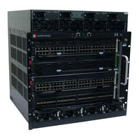
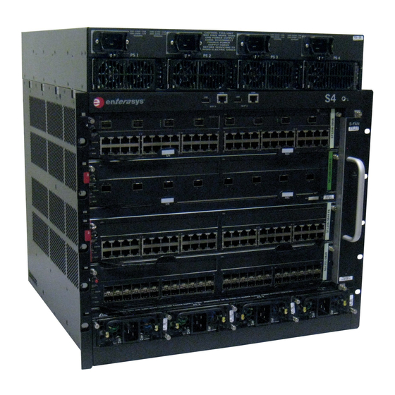
Enterasys S Series Hardware Installation Manual (58 pages)
I/O Module
Brand:
Enterasys
| Category:
Control Unit
| Size: 1 MB
Table of Contents
Table of Contents
13
About this Guide
15
How to Use this Guide
15
Who Should Use this Guide
15
Related Documents
16
Typographical Conventions
16
Getting Help
17
Chapter 1: Introduction
19
Module Types and Chassis Support
19
S-Series Module Support
19
Port Options
20
Option Modules
20
VSB Expansion Module
20
Micro-USB Port
20
Power over Ethernet
21
Management
21
Chapter 2: Installation Requirements and Guidelines
23
Installation Site Requirement
23
S-Series Module Placement and Installation Rules
24
S-Series Module Support
24
Chapter 3: Module Installation
25
Preparation
26
Removing a Coverplate from a Module Slot
26
Installing the Module
27
Inserting a Module into the Chassis
27
Connecting to the Network
28
Engaging Ejector Handles
28
Connecting Category 6 UTP Ethernet Cables to the BASE-T Ports
29
Connecting Pluggable Transceivers to the SFP, SFP+, and QSFP+ Ports
29
Preparation
30
Installing the Pluggable Transceiver
30
Removing the Pluggable Transceiver
31
Completing the Installation
31
Completing the Installation of a New System
31
First-Time Log-In Using a Console Port Connection
32
Completing the Installation of an S-Series Module in an Existing Chassis
33
Logging in with an Administratively-Configured User Account
33
S-Series Startup Screen Example
33
Leds
34
Port Leds
34
10/100/1000 RJ45, SFP, SFP+, and QSFP+ Port Leds
34
10Gb RJ45 Port Leds
35
Module Leds
36
I/O Fabric Module and I/O Module Leds
36
10Gb RJ45 Port LED
36
System Leds
36
Chapter 4: Troubleshooting
39
Troubleshooting Checklist
39
Using the OFFLINE/RESET Button
41
Recommended Shutdown Procedure Using OFFLINE/RESET Button
41
OFFLINE/RESET Button
41
Last Resort Shutdown Procedure Using OFFLINE/RESET Button
42
Appendix A: Specifications
43
Module Specifications
43
SFP, SFP+, and QSFP+ Fiber-Optic Specifications
43
Regulatory Compliance
43
Compliance Standards
43
Appendix B: Mode Switch Bank Setting
45
Required Tools
45
About the Mode Switches
45
Setting the Mode Switches
46
Mode Switch Location
46
Appendix C: Removing an Option Module from an I/O Module
47
Required Tools
47
Removing an Option Module
47
Removing the Top Cover and Faceplate of the I/O Module
48
Removing the Four Pan Head Screws
49
Removing the Option Module from the I/O Module
50
Removing the Poe Power Header (if Necessary
51
Appendix D: about Poe (Power over Ethernet)
53
Overview
53
Proprietary PD Detection
53
Powered Device Classifications
53
Poe Port Status Leds
54
Allocation of Poe Power to Devices
54
Management of Poe Power to Pds
54
Appendix E: Downloading a Firmware Image Via the Serial Port
55
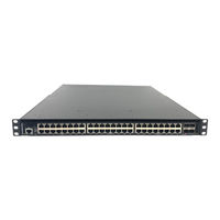
Enterasys S Series Upgrade Installation Manual (48 pages)
PoE Subsystem
Brand:
Enterasys
| Category:
Network Hardware
| Size: 11 MB
Table of Contents
Table of Contents
13
About this Guide
15
Who Should Use this Guide
15
How to Use this Guide
15
Related Documents
16
Typographical Conventions
16
Getting Help
17
Chapter 1: Introduction
19
Poe Upgrade Overview
19
S-Series Poe Upgrade Kits
19
Appendix B: Chassis Bonding and Grounding
20
S3 Chassis with S-POE-4BAY-PWR Poe Subsystem
20
S8 Chassis with S-POE-8BAY-PWR Poe Subsystem
21
Precautions
22
Chapter 2: Installing the Poe Upgrade Kit
23
Required Tools
23
Unpacking the Poe Upgrade Kit
24
Hardware Contents of Poe Upgrade Kit
24
Preparing for Installation
25
ESD Grounding Receptacle (S3 Chassis Example)
25
Installing the Poe Subsystem and the Bus Bar
26
Removing the Poe Cover from the S-Series Chassis
26
Installing the EMI Gasket on the S-Series Chassis
27
Placing the Poe Subsystem on the S-Series Chassis (S3 Chassis/S-POE-4BAY-PWR Example)
28
Securing the Poe Subsystem to the S-Series Chassis (S3 Chassis/S-POE-4BAY-PWR Example)
29
Removing the Rear Panels from the S-Series Chassis and the Poe Subsystem (S3 Chassis/S-POE- 4BAY-PWR Example)
30
Number of Screws to Remove
30
Location of Rear Panel Screws on the S-POE-8BAY-PWR Poe Subsystem
31
Attaching the Poe Subsystem Ribbon Cable to the S-Series Chassis Backplane
32
Installing the Nylon Washers and Spacers on the S3 Chassis Backplane Studs
33
Installing the Nylon Spacers on the S4 and S8 Chassis Backplane Studs (S8 Chassis Example)
34
Poe Connectors on the Bus Bar (S3-POE-BUSBAR Example)
35
Inserting the Bus Bar through the S Chassis into the Poe Subsystem
36
Bus Bar Placed in Front of the S-POE-4BAY-PWR Jumper Plates
37
S8 Bus Bar Sandwiched between the S-POE-8BAY-PWR Jumper Plates
37
Securing the Bus Bar to the Backplane Studs with Hex Nuts (S3 Chassis/S-POE-4BAY-PWR Example)
38
Securing the Bus Bar to the Poe Subsystem's Jumper Plates
39
Reinstalling the Rear Panels of the S Chassis and the Poe Subsystem
40
Chapter 3: Installing the Poe Power Supplies
41
Unpacking the S-POE-PS Power Supplies
41
Contents of S-POE-PS Power Supply Carton
41
Installing the S-POE-PS Power Supplies in the Poe Subsystem
42
Inserting the S-POE-PS Power Supply in the Poe Subsystem
42
Removing a Cover Plate from the Poe Subsystem
43
Appendix A: Specifications and Regulatory Compliance
45
Poe Subsystem Specifications
45
S-POE-PS Power Supply Specifications
45
Torque Values
46
Regulatory Compliance
46
Recommended Torque Values by Screw Size
46
Compliance Standards
46
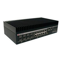
Enterasys S Series Hardware Installation Manual (40 pages)
Option Module
Brand:
Enterasys
| Category:
Control Unit
| Size: 1 MB
Table of Contents
Table of Contents
13
About this Guide
15
How to Use this Guide
15
Who Should Use this Guide
15
Related Documents
16
Typographical Conventions
16
Getting Help
17
Chapter 1: Introduction
19
Option Module Types and Compatibility
19
S-Series Option Module Compatibility
19
Option Module Port Options
20
Power over Ethernet
20
Management
20
Chapter 2: Installing the Option Module
21
Required Tools
21
Unpacking the Option Module
22
Installing the Option Module
22
Removing the Faceplate and Top Cover from the S-Series Module
23
Removing the Option Slot Cover
24
Installing the Poe Power Header for an Option Module with RJ45 Ports
25
Installing the Option Module
26
Securing the Option Module to the S-Series Module
27
Connecting the Option Module to the Network
28
Connecting Category 5 UTP Ethernet Cables to the RJ45 Ports
28
Connecting Pluggable Transceivers to the SFP and SFP+ Ports
29
Leds
30
Option Module Leds (RJ45, SFP, and SFP+ Ports)
30
Port Leds
31
Appendix A: Specifications and Regulatory Compliance
33
Option Module Specifications
33
SFP and SFP+ Fiber-Optic Specifications
33
Regulatory Compliance
33
Compliance Standards
33
Appendix B: Removing an Option Module from an I/O Module
35
Required Tools
35
Removing an Option Module
35
Removing the Top Cover and Faceplate of the I/O Module
36
Removing the Four Pan Head Screws
37
Removing the Option Module from the I/O Module
38
Removing the Poe Power Header (if Necessary
39
Advertisement
Related Products
Enterasys S8-Chassis-POE4
Enterasys S8-Chassis
Enterasys S8-Chassis-POE8
Enterasys S4-Chassis
Enterasys S4-Chassis-POE4
Enterasys S1
Enterasys SSIM-H2-02
Enterasys SSA-T1068-0652
Enterasys SSA-T4068-0252
Enterasys SSA-G1018-0652
Enterasys Categories
Switch
Network Router
Network Hardware
Wireless Access Point
Software
More Enterasys Manuals
Login
Sign In
OR
Sign in with Facebook
Sign in with Google
Upload manual
Upload from disk
Upload from URL