Enterasys S Series Hardware Installation Manual
I/o module
Hide thumbs
Also See for S Series:
- Hardware installation manual (96 pages) ,
- Upgrade installation manual (48 pages) ,
- Hardware installation manual (76 pages)
Table of Contents
Advertisement
Quick Links
Advertisement
Table of Contents

Related Manuals for Enterasys S Series


Summary of Contents for Enterasys S Series
- Page 1 Enterasys S-Series ™ I/O Module Hardware Installation Guide P/N 9034459-07...
- Page 3 Enterasys Networks reserves the right to make changes in specifications and other information contained in this document and its web site without prior notice. The reader should in all cases consult Enterasys Networks to determine whether any such changes have been made.
- Page 4 Regulatory Compliance Information Federal Communications Commission (FCC) Notice This device complies with Part 15 of the FCC rules. Operation is subject to the following two conditions: (1) this device may not cause harmful interference, and (2) this device must accept any interference received, including interference that may cause undesired operation.
- Page 5 It is the users’ responsibility to utilize the available collection system to ensure WEEE is properly treated. For information about the available collection system, please contact Enterasys Customer Support at +353 61 705500 (Ireland).
- Page 6 SJ/T 11363-2006 standard. This table shows where these substances may be found in the supply chain of Enterasys’ electronic information products, as of the date of sale of the enclosed product. Note that some of the component types listed above may or may not be a part of the enclosed product.
- Page 7 Safety Information Class 1 Laser Transceivers The single mode interface modules use Class 1 laser transceivers. Read the following safety information before installing or operating these modules. The Class 1 laser transceivers use an optical feedback loop to maintain Class 1 operation limits. This control loop eliminates the need for maintenance checks or adjustments.
- Page 8 2006/95/EC Manufacturer’s Name: Enterasys Networks, Inc. Manufacturer’s Address: 9 Northeastern Boulevard Salem, NH 03079 European Representative Name: Enterasys Networks Limited European Representative Address: Nexus House, Newbury Business Park London Road, Newbury Berkshire RG14 2PZ, England Conformance to Directive(s)/Product Standards: EC Directive 2004/108/EC...
- Page 9 CAREFULLY READ THIS LICENSE AGREEMENT. This document is an agreement (“Agreement”) between the end user (“You”) and Enterasys Networks, Inc., on behalf of itself and its Affiliates (as hereinafter defined) (“Enterasys”) that sets forth Your rights and obligations with respect to the Enterasys software program/firmware (including any accompanying documentation, hardware or media) (“Program”) in the package...
- Page 10 Agreement. 12. WAIVER. A waiver by Enterasys of a breach of any of the terms and conditions of this Agreement must be in writing and will not be construed as a waiver of any subsequent breach of such term or condition. Enterasys’ failure to enforce a term upon Your breach of such term shall not be construed as a waiver of Your breach or prevent enforcement on any other occasion.
- Page 11 14. TERMINATION. Enterasys may terminate this Agreement immediately upon Your breach of any of the terms and conditions of this Agreement. Upon any such termination, You shall immediately cease all use of the Program and shall return...
-
Page 13: Table Of Contents
Contents About This Guide Who Should Use This Guide ........................... xiii How to Use This Guide ............................ xiii Related Documents ............................xiv Typographical Conventions ..........................xiv Getting Help ..............................xv Chapter 1: Introduction Module Types and Chassis Support ....................... 1-1 Port Options ..............................1-2 Option Modules .............................. - Page 14 Appendix B: Mode Switch Bank Setting Required Tools ...............................B-1 About the Mode Switches ..........................B-1 Setting the Mode Switches ..........................B-2 Appendix C: Removing an Option Module from an I/O Module Required Tools ...............................C-1 Removing an Option Module ..........................C-1 Appendix D: About PoE (Power over Ethernet) Overview .................................D-1 Proprietary PD Detection ..........................D-1 PoE Port Status LEDs ............................D-2...
-
Page 15: About This Guide
A brief summary of each chapter • Definitions of the conventions used in this document • Instructions regarding how to obtain technical support from Enterasys Networks. To locate information about various subjects in this guide, refer to the following table. For... Refer to... -
Page 16: Related Documents
Image via the Serial Port Related Documents The Enterasys S-Series Configuration Guide and Enterasys S-Series CLI Reference provide information on how to use the CLI to set up and manage the S-Series modules. These manuals can be obtained from the World Wide Web in Adobe Acrobat Portable Document Format (PDF) at the following site: https://extranet.enterasys.com/downloads/... -
Page 17: Getting Help
A description of any action(s) already taken to resolve the problem (for example, changing mode switches or rebooting the unit) • The serial and revision numbers of all involved Enterasys Networks products in the network • A description of your network environment (such as layout, cable type, other relevant environmental information) •... - Page 18 Getting Help xvi About This Guide...
-
Page 19: Chapter 1: Introduction
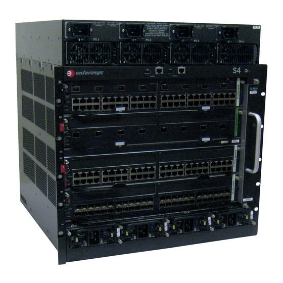
S-Series chassis in which you can install the module. For example, the label on an S180 I/O fabric module indicates that the module can only be installed in an S8, S6, S4, or S1 chassis. Enterasys S-Series I/O Module Hardware Installation Guide 1-1... -
Page 20: Port Options
Some S-Series S180 class I/O modules can be expanded with a VSB expansion module, which has four 10GBASE-X SFP+ ports, for virtual switch bonding of two co-located S-Series chassis. For VSB configuration CLI commands, refer to the Enterasys S-Series Configuration Guide at https://extranet.enterasys.com/downloads/. -
Page 21: Power Over Ethernet
(CLI) via Telnet. Out-of-band management is provided through the RJ45 COM (Communication) port on the front panel of the S-Series chassis using a PC, a VT terminal, or a VT terminal emulator. Enterasys S-Series I/O Module Hardware Installation Guide 1-3... - Page 22 Management 1-4 Introduction...
-
Page 23: Chapter 2: Installation Requirements And Guidelines
If you are installing the S-Series modules in an S3 chassis, the chassis must be located in a Restricted Access Location (RAL) if it is equipped with a PoE subsystem. Enterasys S-Series I/O Module Hardware Installation Guide 2-1... -
Page 24: S-Series Module Placement And Installation Rules
S8, S6, S4, or S1 chassis. For a complete list of the S-Series I/O modules and I/O fabric modules that are currently available, refer to the S-Series datasheet at http://www.enterasys.com/products. 2-2 Installation Requirements and Guidelines... -
Page 25: Chapter 3: Module Installation
Follow the order of the sections listed below to correctly install the modules. For information about... Refer to page... Preparation Installing the Module Connecting to the Network Completing the Installation LEDs 3-10 Enterasys S-Series I/O Module Hardware Installation Guide 3-1... -
Page 26: Preparation
Observe all precautions to prevent damage from Electrostatic Discharge (ESD). Save the bag in the event the module must be reshipped. Examine the module for damage. If any damage exists, DO NOT install the module. Immediately contact Enterasys Networks. Refer to “Getting Help”... -
Page 27: Installing The Module
Ensure that the module is in both the right and left guide rails. Figure 3-2 Inserting a Module into the Chassis Module Captive screws Gently slide the module into the slot until the module engages the connector on the backplane. Enterasys S-Series I/O Module Hardware Installation Guide 3-3... -
Page 28: Connecting To The Network
Link Aggregation to operate properly. Before connecting the cables, refer to the Enterasys S-Series Configuration Guide for the configuration information. For details on how to obtain manuals, refer to “Related... -
Page 29: Connecting Category 6 Utp Ethernet Cables To The Base-T Ports
QSFP+ to four SFP+ cable conversion. See the set port speed command information Enterasys S-Series CLI Reference for port configuration details. Note: Enterasys QSFP+ to SFP+ adapter (model number QSFP-SFPP-ADPT) to support 10 Gigabit Ethernet SFP+ transceivers in QSFP+ ports. The 10GB-LRM-SFPP SFP+ transceiver is only supported on the S-Series devices in native SFP+ ports. -
Page 30: Preparation
Connecting to the Network Warning: Fiber-optic pluggable transceivers use Class 1 lasers. Do not use optical instruments to view the laser output. The use of optical instruments to view laser output increases eye hazard. When viewing the output optical port, power must be removed from the network adapter. Advertencia: Los transmisores receptores de fibra óptica SFP, SFP+, y QSFP+ conectables utilizan sistemas de láser clase 1. -
Page 31: Removing The Pluggable Transceiver
After installing all S-Series modules into the host chassis and making the connections to the network, proceed to “First-Time Log-In Using a Console Port Connection” on page 3-8 to access the module management startup screen from your PC, terminal, or modem connection. Enterasys S-Series I/O Module Hardware Installation Guide 3-7... -
Page 32: First-Time Log-In Using A Console Port Connection
The S-Series module is now ready to be configured. For information about setting the IP address and configuring Telnet settings for remote access to S-Series module management, refer to the Enterasys S-Series Configuration Guide. The CLI commands enable you to initially set up and perform more involved management configurations. -
Page 33: Completing The Installation Of An S-Series Module In An Existing Chassis
Completing the Installation The Enterasys S-Series Configuration Guide is available online at: https://extranet.enterasys.com/downloads/ If you require assistance, contact Enterasys Networks using one of the methods described in “Getting Help” on page xv. Figure 3-4 S-Series Startup Screen Example login: admin... -
Page 34: Leds
For information on the set password and set system login commands, refer to the Enterasys S-Series Configuration Guide LEDs The S-Series modules have port and module LEDs. -
Page 35: 10Gb Rj45 Port Leds
None Port is off due to another reason. Figure 3-6 shows the port LEDs for 10Gb RJ45 ports. Figure 3-6 10Gb RJ45 Port LEDs Upper port status LED Lower port status LED Enterasys S-Series I/O Module Hardware Installation Guide 3-11... -
Page 36: Module Leds
LEDs Table 3-3 describes the port LED indications for 10Gb RJ45 ports. Table 3-3 10Gb RJ45 Port LED Color Status None No link. No activity. Port enabled or disabled. Green Solid. Link present. Blinking. The interface is transmitting traffic. Green and Yellow Alternating. - Page 37 This module is not the management None. module. Green Solid. This module is the designated None. management module. Amber Amber. This is a temporary indication that None. the module is saving data. Enterasys S-Series I/O Module Hardware Installation Guide 3-13...
- Page 38 LEDs 3-14 Module Installation...
-
Page 39: Chapter 4: Troubleshooting
“Setting the Mode screen. entered. Switches,” on page B-2 for instructions on how to set the mode switch to reset the username/password combination to the default values. Enterasys S-Series I/O Module Hardware Installation Guide 4-1... - Page 40 Table 4-1 Troubleshooting Checklist (continued) Problem Possible Cause Recommended Action Cannot contact the IP address not assigned. Refer to the Enterasys S-Series Configuration Guide module through for the IP address assignment procedure. in-band Port is disabled. Enable port. Refer to the Enterasys S-Series management.
-
Page 41: Using The Offline/Reset Button
At this time it is safe to restart the S-Series module. When you initiate a controlled shutdown with the OFFLINE/RESET button, you have 60 seconds from the time the CPU LED starts flashing amber/off until the device automatically restarts. Enterasys S-Series I/O Module Hardware Installation Guide 4-3... -
Page 42: Last Resort Shutdown Procedure Using Offline/Reset Button
Using the OFFLINE/RESET Button Last Resort Shutdown Procedure Using OFFLINE/RESET Button Caution: This method of shutting down a module is not recommended except as a last resort, because all processes currently running on the module will be interrupted resulting in loss of frames. -
Page 43: Appendix A: Specifications
(Class A), EN 55024, EN 61000-3-2, EN 61000-3-3, AS/NZS CISPR-22 (Class A). VCCI V-3. CNS 13438 (BSMI), 2004/108/EC (EMC Directive) Environmental 2011/65/EU (RoHS Directive), 2012/19/EU (WEEE Directive), Ministry of Information Order #39 (China RoHS) Enterasys S-Series I/O Module Hardware Installation Guide A-1... - Page 44 Regulatory Compliance A-2 Specifications...
-
Page 45: Appendix B: Mode Switch Bank Setting
Switches 1–6: For Enterasys Networks use only. • Switch 7: Clear Persistent Data. Changing the position of this switch clears Persistent Data on the next power-up of the module. All user-entered parameters, such as the IP address, system Enterasys S-Series I/O Module Hardware Installation Guide B-1... -
Page 46: Setting The Mode Switches
Setting the Mode Switches name, and so on, are reset to the factory default settings. Once the system resets, you can either use the factory default settings or reenter your own parameters. • Switch 8: Clear Admin Password. Changing the position of this switch clears the admin password, and restores the factory default password on the next power-up of the system. -
Page 47: Appendix C: Removing An Option Module From An I/O Module
This procedure is also applicable to those I/O modules. Attach the anti-static wrist strap. Refer to the instructions on the anti-static wrist strap package. Place the I/O module on an anti-static pad on a sturdy, flat surface. Enterasys S-Series I/O Module Hardware Installation Guide C-1... -
Page 48: Removing The Top Cover And Faceplate Of The I/O Module
Removing an Option Module Remove the eleven screws fastening the top cover and faceplate to the main board of the I/O module (five screws on top, two screws on the sides, four screws on the bottom). See Figure C-1. Set aside the top cover, faceplate, and screws for reinstallation at the end of this procedure. Figure C-1 Removing the Top Cover and Faceplate of the I/O Module Top cover... -
Page 49: Removing The Four Pan Head Screws
Keep the screws with the option module. If you install an option slot coverplate after you have removed the option module, you will need to use two of the pan head screws. Figure C-2 Removing the Four Pan Head Screws Pan head screws Option module Enterasys S-Series I/O Module Hardware Installation Guide C-3... -
Page 50: Removing The Option Module From The I/O Module
Removing an Option Module With your fingers under the faceplate and on the back edge of the option module, gently rock the option module back and forth 10 to 15 times while lifting the option module straight off the I/O module motherboard connectors. See Figure C-3. -
Page 51: Removing The Poe Power Header (If Necessary
I/O module in the chassis. Reinstall the faceplate and top cover of the I/O module. You can now install the I/O module in an S-Series chassis. Enterasys S-Series I/O Module Hardware Installation Guide C-5... - Page 52 Removing an Option Module C-6 Removing an Option Module from an I/O Module...
-
Page 53: Appendix D: About Poe (Power Over Ethernet)
Reserved 12.95 to 25.50 watts Proprietary PD Detection S-Series devices support a subset of the currently deployed proprietary PoE methods. This includes support for Cisco PDs, including a proprietary capacitor-based detection scheme. Enterasys S-Series I/O Module Hardware Installation Guide D-1... -
Page 54: Poe Port Status Leds
If the PoE power needed or requested exceeds the power available, the system will generate a trap to notify the system manager. For more information on configuring allocation mode, see the Enterasys S-Series CLI Reference. Management of PoE Power to PDs You can configure how the S-Series chassis makes power available to attached PDs: •... -
Page 55: Appendix E: Downloading A Firmware Image Via The Serial Port
- change boot image file showboot - display boot image file clearnvram - clear persistent storage [System Image Loader]: Use the list command to display the images currently on this device. Enterasys S-Series I/O Module Hardware Installation Guide E-1... - Page 56 The baud rate can be set to 9600, 38400, 57600, or 115200. Using the setbaud command, set the baud rate to 115200: [System Image Loader]: setbaud 1152000 ###Change the baud of the terminal program to 1152000### [System Image Loader]: Use the download command to start the ZMODEM receive process. Send the image file using the ZModem protocol from your terminal application.
- Page 57 /flash0/ - Volume is OK Loading 61205... DONE. Uncompressing System Image... DONE. Loading System Image... DONE. Initializing Platform Hardware If you require assistance, contact Enterasys Networks Technical Support. Refer to “Getting Help” on page xv. Enterasys S-Series I/O Module Hardware Installation Guide E-3...
- Page 58 E-4 Downloading a Firmware Image via the Serial Port...
Need help?
Do you have a question about the S Series and is the answer not in the manual?
Questions and answers