Sign In
Upload
Manuals
Brands
Enterasys Manuals
Chassis
S4-Chassis-POE4
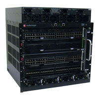
User Manuals: Enterasys S4-Chassis-POE4 Switch Chassis
Manuals and User Guides for Enterasys S4-Chassis-POE4 Switch Chassis. We have
2
Enterasys S4-Chassis-POE4 Switch Chassis manuals available for free PDF download: Hardware Installation Manual
Enterasys S4-Chassis-POE4 Hardware Installation Manual (76 pages)
Brand:
Enterasys
| Category:
Chassis
| Size: 10 MB
Table of Contents
Table of Contents
13
About this Guide
17
Who Should Use this Guide
17
How to Use this Guide
17
Related Documents
18
Typographical Conventions
18
Getting Help
19
Chapter 1: Introduction
21
Overview
21
S4 Chassis (S4-Chassis)
22
S4 Chassis with Four Bay Poe Subsystem (S4-Chassis-POE4)
23
Features
24
AC Power Supplies
24
Models
24
Redundancy
24
S-Series Modules
24
Auto-Ranging Input Voltage and Frequency
25
DC Power Supplies
25
Hot Swapping
25
Operating Status
25
Power over Ethernet (Poe)
26
RJ45 COM Ports
26
Standalone or Rack Mountable Chassis
26
The S-FAN Chassis Cooling System
26
USB Ports
26
Chapter 2: Installation Requirements and Guidelines
27
Site Guidelines
27
Location Guidelines
27
Rack Mounting Guidelines
27
AC Power Supply Guidelines
28
Temperature Guidelines
28
Precautions
28
Chapter 3 : Chassis Setup
30
Required Tools
30
Unpacking the S4 Chassis
30
Accessories that Ship with the S-Series Chassis
30
Installing the S4 Chassis
31
Order of Installation
31
Installing Rubber Feet
32
Installing the MID-Mount Brackets
32
Attaching the MID-Mount Brackets to the Sides of the Chassis
32
Rack Mounting the S4 Chassis
33
Attaching the MID-Mount Brackets to the Front of the Chassis
33
Front Mounting an S4 Chassis
34
Front Mounting the S4 Chassis in a Rack
34
MID-Mounting an S4 Chassis
35
MID-Mounting the S4 Chassis in a Rack
35
Installing the Cable Management Clips
36
Installing a Cable Management Clip in the Left Mounting Bracket
36
Removing the Swing Arm from the Bottom Cable Management Clip
37
Closing a Cable Management Clip
37
S4 Chassis with Cable Management Clips
38
Opening a Cable Management Clip
38
Chassis Bonding and Grounding
39
Telcordia GR-1089 Grounding Hole Pattern
39
Attaching the Electrostatic Discharge Wrist Strap
40
ESD Grounding Receptacle
40
Installing and Removing an AC Power Supply
41
Power Supply Planning
41
Installing the AC Power Supplies
42
Unpacking the AC Power Supplies
42
Contents of AC Power Supply Carton
42
Installing an AC Power Supply
43
Removing an AC Power Supply
44
Removing a Coverplate from a Power Supply Slot
44
Powering up the S4 Chassis with AC Power Supplies
45
Installing and Removing an S-DC-PS Power Supply
46
Prepare Site Wiring for DC Power Installation
46
Installing the S-DC-PS Power Supply
47
Unpacking an S-DC-PS Power Supply
47
Contents of S-DC-PS Carton
47
Installing the S-DC-PS Power Supply
48
Removing an S-DC-PS Power Supply
49
Powering up the S4 Chassis with S-DC-PS Power Supplies
50
Cabling the S-DC-PS Power Supply
50
Removing and Installing a Fan Tray
51
Removing a Fan Tray
51
Removing the Fan Tray
51
Installing a Fan Tray
52
Installing and Removing an S-POE-PS Power Supply
52
Unpacking the S-POE-PS Power Supplies
52
Contents of S-POE-PS Power Supply Carton
52
Installing the S-POE-PS Power Supplies in the Poe Subsystem
53
Inserting the S-POE-PS Power Supply in the Poe Subsystem
53
Removing an S-POE-PS Power Supply
54
Removing Cover Plates from the Poe Subsystem Power Supply Slots
54
Connecting Power to the S-POE-PS Power Supplies
55
Leds
56
AC Power Supply Leds
56
AC Power Supply Leds (S-AC-PS Shown)
56
AC Power Supply LED Status Definitions
56
S-FAN Fan Tray Status LED
57
Fan Tray Status LED
57
Fan Tray Status LED States and Their Definitions
57
S-POE-PS Power Supply Leds
58
S-POE-PS Power Supply LED Status Definitions
58
S-DC-PS Power Supply Leds
59
Connecting to the COM Port for Local Management
59
What Is Needed
59
S-DC-PS Power Supply LED Status Definitions
59
Connecting to a PC or Laptop
60
Connecting to a VT Series Terminal
60
Adapter Wiring and Signal Assignments
61
COM Port Adapter Wiring
61
VT Series Port Adapter Wiring
61
Completing the Installation
62
Appendix A: Specifications and Regulatory Compliance
63
S4 Chassis Specifications
63
S-AC-PS Power Supply Specifications
64
S-AC-PS-15A Power Supply Specifications
64
S-DC-PS Power Supply Specifications
65
S-POE-PS Power Supply Specifications
65
S-FAN Fan Tray Specifications
65
Torque Values
66
COM Port Pinout Assignments
66
Recommended Torque Values by Screw Size
66
COM Port Pin Assignments
66
Regulatory Compliance
67
Compliance Standards
67
Appendix B: about Poe (Power over Ethernet)
69
Overview
69
Proprietary PD Detection
69
Powered Device Classifications
69
Poe Port Status Leds
70
Allocation of Poe Power to Devices
70
Management of Poe Power to Pds
70
Appendix C: Environmental Guidelines
71
Temperature and Humidity Guidelines
71
Operating Temperatures
71
Inlet Air Temperature Measurement
71
Cooling Air
71
Power Conditioning
71
Airflow Concerns for Closed Racks
72
Closed Rack Ideal Configuration
72
Airflow Concerns for Open Racks
73
Open Rack Ideal Configuration
73
Non-Ideal Open Rack Configuration
74
Mitigated Non-Ideal Open Rack Configuration
74
Dust Mitigation and Prevention
75
Another Mitigated Non-Ideal Open Rack Configuration
75
Airborne Chemicals and Prevention
76
Airborne Dust Specification for Enterasys Equipment - Airborne Dust Maximum Values
76
Advertisement
Enterasys S4-Chassis-POE4 Hardware Installation Manual (68 pages)
S-Series
Brand:
Enterasys
| Category:
Chassis
| Size: 14 MB
Table of Contents
Industry Canada Notice
4
Safety Compliance
7
Safety Information
7
Declaration of Conformity
8
Table of Contents
13
About this Guide
17
Who Should Use this Guide
17
How to Use this Guide
17
Related Documents
18
Typographical Conventions
18
Getting Help
19
Chapter 1: Introduction
21
Overview
21
S8 Chassis (S8-Chassis)
22
S8 Chassis with Four Bay Poe Subsystem (S8-Chassis-POE4)
23
S8 Chassis with Eight Bay Poe Subsystem (S8-Chassis-POE8)
24
Features
25
S-Series Modules
25
Redundant Power Supplies
25
Power Supply Status
25
Auto-Ranging Power Supplies
25
Power Supply Replacement
26
The S-FAN Chassis Cooling System
26
Standalone or Rack Mountable Chassis
26
RJ45 COM Ports
26
USB Ports
26
Power over Ethernet (Poe)
27
Chapter 2: Installation Requirements and Guidelines
29
Site Guidelines
29
Precautions
30
Chapter 3 : Chassis Setup
31
Required Tools
31
Unpacking the S8 Chassis
32
Accessories that Ship with the S-Series Chassis
32
Installing the S8 Chassis
33
Order of Installation
33
Installing Rubber Feet
34
Installing the MID-Mount Brackets
34
Attaching the MID-Mount Brackets to the Sides of the Chassis
34
Attaching the MID-Mount Brackets to the Front of the Chassis
35
Rack Mounting the S8 Chassis
36
Front Mounting an S8 Chassis
37
Front Mounting the S8 Chassis in a Rack
37
MID-Mounting an S8 Chassis
38
MID-Mounting the S8 Chassis in a Rack
38
Installing the Cable Management Clips
39
Installing a Cable Management Clip in the Left Mounting Bracket
39
Removing the Swing Arm from the Bottom Cable Management Clip
40
Closing a Cable Management Clip
40
S8 Chassis with Cable Management Clips
41
Opening a Cable Management Clip
42
Chassis Bonding and Grounding
43
Telcordia GR-1089 Grounding Hole Pattern
43
Attaching the Electrostatic Discharge Wrist Strap
44
Installing and Removing an S-AC-PS Power Supply
44
ESD Grounding Receptacle
44
Power Supply Planning
45
Unpacking the S-AC-PS Power Supplies
45
Contents of S-AC-PS Power Supply Carton
45
Installing the S-AC-PS Power Supplies
46
Installing the S-AC-PS Power Supply
47
Removing an S-AC-PS Power Supply
48
Removing a Coverplate from an S-AC-PS Power Supply Slot
48
Powering up the S8 Chassis
49
Removing and Installing a Fan Tray
49
Removing a Fan Tray
49
Installing a Fan Tray
50
Removing the Fan Tray
50
Installing and Removing an S-POE-PS Power Supply
51
Unpacking the S-POE-PS Power Supplies
51
Contents of S-POE-PS Power Supply Carton
51
Installing the S-POE-PS Power Supplies in the Poe Subsystem
52
Inserting the S-POE-PS Power Supply in the Poe Subsystem
52
Removing an S-POE-PS Power Supply
53
Removing Cover Plates from the Poe Subsystem Power Supply Slots
53
Connecting Power to the S-POE-PS Power Supplies
54
Leds
55
S-AC-PS Power Supply Leds
55
S-AC-PS Power Supply LED Status Definitions
55
S-FAN Fan Tray Status LED
56
Fan Tray Status LED
56
Fan Tray Status LED States and Their Definitions
56
S-POE-PS Power Supply Leds
57
S-POE-PS Power Supply LED Status Definitions
57
Connecting to the COM Port for Local Management
58
What Is Needed
58
Connecting to a PC or Laptop
58
Connecting to a VT Series Terminal
59
Adapter Wiring and Signal Assignments
60
Completing the Installation
61
Appendix A: Specifications and Regulatory Compliance
63
S8 Chassis Specifications
63
Power Supply Specifications
64
S-FAN Fan Tray Specifications
64
S-AC-PS Power Supply Specifications
64
S-POE-PS Power Supply Specifications
64
Torque Values
65
COM Port Pinout Assignments
65
Recommended Torque Values by Screw Size
65
COM Port Pin Assignments
65
Regulatory Compliance
66
Compliance Standards
66
Appendix B: about Poe (Power over Ethernet)
67
Overview
67
Proprietary PD Detection
67
Powered Device Classifications
67
Poe Port Status Leds
68
Allocation of Poe Power to Devices
68
Management of Poe Power to Pds
68
Advertisement
Related Products
Enterasys S4-Chassis
Enterasys S8-Chassis-POE4
Enterasys S8-Chassis
Enterasys S8-Chassis-POE8
Enterasys S Series
Enterasys S1
Enterasys S4-POE-4BAY-UGK
Enterasys Sentinel SNS-TAG-LPA
Enterasys S150
Enterasys SSA-T8028-0652
Enterasys Categories
Switch
Network Router
Network Hardware
Wireless Access Point
Software
More Enterasys Manuals
Login
Sign In
OR
Sign in with Facebook
Sign in with Google
Upload manual
Upload from disk
Upload from URL