Enterasys S Series Hardware Installation Manual
Hide thumbs
Also See for S Series:
- Hardware installation manual (96 pages) ,
- Upgrade installation manual (48 pages) ,
- Hardware installation manual (68 pages)

Related Manuals for Enterasys S Series


Summary of Contents for Enterasys S Series
- Page 1 Enterasys S-Series ® S4 Chassis Hardware Installation Guide S4-Chassis S4-Chassis-POE4 P/N 9034439-08...
- Page 3 Enterasys Networks reserves the right to make changes in specifications and other information contained in this document and its web site without prior notice. The reader should in all cases consult Enterasys Networks to determine whether any such changes have been made.
- Page 4 Regulatory Compliance Information Federal Communications Commission (FCC) Notice This device complies with Part 15 of the FCC rules. Operation is subject to the following two conditions: (1) this device may not cause harmful interference, and (2) this device must accept any interference received, including interference that may cause undesired operation.
- Page 5 It is the users’ responsibility to utilize the available collection system to ensure WEEE is properly treated. For information about the available collection system, please go to www.enterasys.com/support/ or contact Enterasys Customer Support at 353 61 705586 (Ireland). Battery Notice This product contains a battery used to maintain product information.
- Page 6 SJ/T 11363-2006 standard. This table shows where these substances may be found in the supply chain of Enterasys’ electronic information products, as of the date of sale of the enclosed product. Note that some of the component types listed above may or may not be a part of the enclosed product.
- Page 7 Safety Information Class 1 Laser Transceivers The single mode interface modules use Class 1 laser transceivers. Read the following safety information before installing or operating these modules. The Class 1 laser transceivers use an optical feedback loop to maintain Class 1 operation limits. This control loop eliminates the need for maintenance checks or adjustments.
- Page 8 EC Directive 2006/95/EC EN 60950-1:2006 A11:2009 A1:2010 EN 60825-1:2007 EN 60825-2:2004 A1:2007 Equipment Type/Environment: Information Technology Equipment, for use in a Commercial or Light Industrial Environment. Enterasys Networks, Inc. declares that the equipment packaged with this notice conforms to the above directives.
- Page 9 CAREFULLY READ THIS LICENSE AGREEMENT. This document is an agreement (“Agreement”) between the end user (“You”) and Enterasys Networks, Inc., on behalf of itself and its Affiliates (as hereinafter defined) (“Enterasys”) that sets forth Your rights and obligations with respect to the Enterasys software program/firmware (including any accompanying documentation, hardware or media) (“Program”) in the package...
- Page 10 Agreement. 12. WAIVER. A waiver by Enterasys of a breach of any of the terms and conditions of this Agreement must be in writing and will not be construed as a waiver of any subsequent breach of such term or condition. Enterasys’ failure to enforce a term upon Your breach of such term shall not be construed as a waiver of Your breach or prevent enforcement on any other occasion.
- Page 11 14. TERMINATION. Enterasys may terminate this Agreement immediately upon Your breach of any of the terms and conditions of this Agreement. Upon any such termination, You shall immediately cease all use of the Program and shall return...
-
Page 13: Table Of Contents
Contents About This Guide Who Should Use This Guide ..........................xv How to Use This Guide .............................xv Related Documents ............................xvi Typographical Conventions ..........................xvi Getting Help ..............................xvii Chapter 1: Introduction Overview ................................. 1-1 Features ................................. 1-4 S-Series Modules ............................. 1-4 AC Power Supplies .......................... - Page 14 Powering Up the S4 Chassis with AC Power Supplies ................3-17 Installing and Removing an S-DC-PS Power Supply ................... 3-18 Prepare Site Wiring for DC Power Installation ..................3-18 Unpacking an S-DC-PS Power Supply ....................3-19 Installing the S-DC-PS Power Supply ....................3-19 Removing an S-DC-PS Power Supply ....................
- Page 15 S-POE-PS Power Supply Specifications ....................A-3 S-FAN Fan Tray Specifications ......................A-3 Recommended Torque Values by Screw Size ...................A-4 COM Port Pin Assignments ........................A-4 Compliance Standards ........................A-5 Powered Device Classifications ......................B-1 Airborne Dust Specification for Enterasys Equipment — Airborne Dust Maximum Values....C-6 xiii...
-
Page 17: About This Guide
A brief summary of each chapter • Definitions of the conventions used in this document • Instructions regarding how to obtain technical support from Enterasys Networks. To locate information about various subjects in this guide, refer to the following table. For... Refer to... -
Page 18: Related Documents
• Enterasys S-Series Configuration Guide and Enterasys S-Series CLI Reference Guide provide information on how to use the Command Line Interface to set up and manage the Enterasys S4 chassis and S-Series modules. • Enterasys S-Series I/O Module Hardware Installation Guide •... -
Page 19: Getting Help
A description of any action(s) already taken to resolve the problem (for example, changing mode switches or rebooting the unit) • The serial and revision numbers of all involved Enterasys Networks products in the network • A description of your network environment (such as layout, cable type, other relevant environmental information) •... - Page 20 Getting Help xviii About This Guide...
-
Page 21: Chapter 1: Introduction
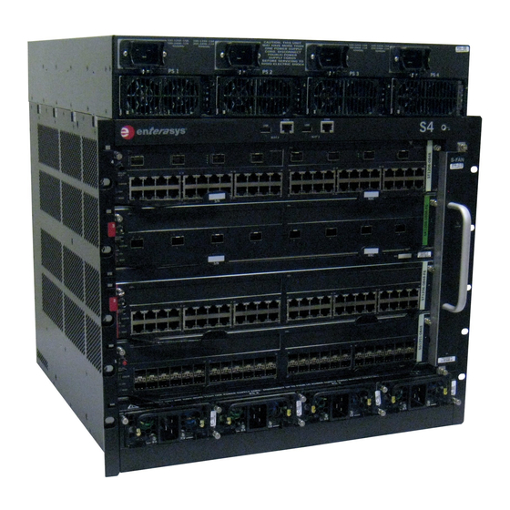
S4 chassis (S4-Chassis) with slots for two I/O fabric modules, two I/O modules, and four redundant power supplies. Figure 1-2 shows the S4 chassis equipped with the four bay PoE subsystem (S4-Chassis-POE4). Enterasys S-Series S4 Chassis Hardware Installation Guide 1-1... -
Page 22: S4 Chassis (S4-Chassis)
Features Figure 1-1 S4 Chassis (S4-Chassis) 1 Module slots (4 total) 4 Fan tray (S-FAN) 2 USB ports (2 ports) 5 Power supply slots (AC or DC power supplies) (4) 3 Slot-specific COM ports (2 ports) 1-2 Introduction... -
Page 23: S4 Chassis With Four Bay Poe Subsystem (S4-Chassis-Poe4)
Features Figure 1-2 S4 Chassis with Four Bay PoE Subsystem (S4-Chassis-POE4) 1 Chassis (S4-Chassis) 2 PoE power supply slots 3 AC power receptacles (S-POE-PS) (4) Enterasys S-Series S4 Chassis Hardware Installation Guide 1-3... -
Page 24: Features
Features Features S-Series Modules The S4 chassis supports S-Series S130 and S155 I/O fabric modules and I/O modules, with some of these modules designed to be expanded with option modules. Port options on the S-Series modules are 10/100/1000BASE-TX RJ45 ports, 1000BASE-X SFP ports, and 10GBASE-X SFP+ ports. IEEE 802.3af and 802.3at Power over Ethernet (PoE) is supported on the 10/100/1000BASE-TX RJ45 ports. -
Page 25: Operating Status
Power supply status (normal/fault/not installed) • Power supply redundancy indication (redundant/not available) Refer to the Enterasys S-Series CLI Reference Guide for instructions on how to access power supply status information using Local Management. Auto-Ranging Input Voltage and Frequency The S-AC-PS and S-AC-PS-15A power supplies automatically adjust to the input voltage and frequency, which allows for an input voltage of 100 to 220 Vac, and a frequency between 50 and 60 Hz. -
Page 26: The S-Fan Chassis Cooling System
I/O fabric module is present in the corresponding slot. In the S4 chassis, the USB ports correspond to slots 2 and 3. For information on connecting to the USB port, refer to the Enterasys S-Series CLI Reference Guide. Power over Ethernet (PoE) The S4 chassis provides PoE to powered devices (PDs) using the PoE subsystem installed on top of the S-Series chassis. -
Page 27: Chapter 2: Installation Requirements And Guidelines
• To install the S4 chassis as a rack mounted unit, care must be taken to ensure that the rack used will support the unit and that the rack remains stable. Enterasys S-Series S4 Chassis Hardware Installation Guide 2-1... -
Page 28: Ac Power Supply Guidelines
Ensure that you have read and understood the installation and operation precautions before installing the S4 chassis. Warning: Install the Enterasys S-Series chassis in a Restricted Access Location only. Access to the equipment by users must be restricted through the use of a tool or lock and key or other means of security and is controlled by the authority responsible for the location. - Page 29 Completing the Installation 3-34 Important Notice Read the Release Notes specific to the firmware image running in the chassis to check for any exceptions to the supported features and operation documented in this guide. Enterasys S-Series S4 Chassis Hardware Installation Guide 3-1...
-
Page 30: Required Tools
Lift and remove the chassis from the skid. Save all shipping materials for future reshipping, if necessary. Inspect the chassis for any signs of physical damage. If there are any signs of damage, DO NOT install the chassis; instead, contact Enterasys Networks. Refer to “Getting Help”... -
Page 31: Installing The S4 Chassis
If you have an S4 chassis with a PoE subsystem, install the PoE power supplies (Installing the S-POE-PS Power Supplies in the PoE Subsystem). Power up the PoE power supplies (Connecting Power to the S-POE-PS Power Supplies). Enterasys S-Series S4 Chassis Hardware Installation Guide 3-3... -
Page 32: Installing Rubber Feet
Installing the S4 Chassis Installing Rubber Feet To install the rubber feet: Place the chassis on its side on a sturdy flat surface to access the bottom of the chassis. Remove the four rubber feet/screw assemblies from their plastic bag in the shipping box. Locate the four tapped holes in the four corners on the bottom of the chassis. -
Page 33: Rack Mounting The S4 Chassis
Esto ayuda a prevenir que el rack este demasiado pesado en la parte superior. Warnhinweis: Falls das Rack nicht mit Schrauben am Boden gesichert wird, sollte das Chassis in der unteren Hälfte des Racks installiert werden, um ein kippen des Racks zu vermeiden. Enterasys S-Series S4 Chassis Hardware Installation Guide 3-5... -
Page 34: Front Mounting An S4 Chassis
Installing the S4 Chassis Caution: Read Chapter 2 before completing the following procedure to ensure that all installation guidelines are met. Precaución: Antes de llevar a cabo el siguiente procedimiento, lea Chapter 2 para y asegúrese de cumplir con todos los requisitos de instalación. Front Mounting an S4 Chassis To install the S4 chassis in a rack using the S4 chassis front mounting brackets: Warning: To help prevent personal injury, at least two people are required to lift the chassis into... -
Page 35: Mid-Mounting An S4 Chassis
Table A-7 on page A-4 for recommended torque values to use when installing the S4 chassis using standard threaded fastener machine screws and bolts. Figure 3-4 Mid-Mounting the S4 Chassis in a Rack Enterasys S-Series S4 Chassis Hardware Installation Guide 3-7... -
Page 36: Installing The Cable Management Clips
Installing the S4 Chassis Installing the Cable Management Clips Note: Installing the cable management clips is optional. If your installation location does not have the space needed for installing the cable management clips (for example, in an enclosed rack), do not install the cable management clips. -
Page 37: Removing The Swing Arm From The Bottom Cable Management Clip
Install the bottom cable management clip on the left mounting bracket. Close each cable management clip by snapping its swing arm into the cable management clip below. See Figure 3-7. Figure 3-7 Closing a Cable Management Clip Enterasys S-Series S4 Chassis Hardware Installation Guide 3-9... -
Page 38: S4 Chassis With Cable Management Clips
Installing the S4 Chassis Figure 3-8 shows the completed installation. Figure 3-8 S4 Chassis with Cable Management Clips Once you have installed and cabled an S-Series module, open the appropriate cable management clip by pushing up on the latch of its swing arm where it attaches to the cable management clip below. -
Page 39: Chassis Bonding And Grounding
Connect one ground cable two-hole connector to the chassis using two of the 1/4-20 screws shipped with the chassis. Connect the two-hole connector at the other end of the cable to the CO Ground or enclosure metalwork using user-supplied screws. Enterasys S-Series S4 Chassis Hardware Installation Guide 3-11... -
Page 40: Attaching The Electrostatic Discharge Wrist Strap
Attaching the Electrostatic Discharge Wrist Strap Torque screws to 67 inch pounds (± 5%). National Deviations: • In Norway, Sweden, and Finland, the same procedure can be used for a permanent protective earth ground connection as required by their national deviation to IEC 60950, Section 5.1.7. •... -
Page 41: Installing And Removing An Ac Power Supply
The number of power supplies required in an S4 chassis is determined by the number and types of modules installed in the chassis and your power supply redundancy strategy. Enterasys S-Series S4 Chassis Hardware Installation Guide 3-13... -
Page 42: Unpacking The Ac Power Supplies
3-2. Remove the power supply from its protective plastic bag. Examine the power supply carefully, checking for damage. If any damage is noted, DO NOT install the power supply. Contact Enterasys Networks immediately. Refer to “Getting Help” on page xvii for details. -
Page 43: Installing An Ac Power Supply
1 Mandatory power supply installed in slot PS1 4 Faceplate 2 Captive screw 5 Power supply slot 3 Power supply handle Secure the power supply to the chassis by screwing the captive screws into the chassis. Enterasys S-Series S4 Chassis Hardware Installation Guide 3-15... -
Page 44: Removing An Ac Power Supply
Installing and Removing an AC Power Supply If you are installing more than one power supply, remove the coverplates from the applicable number of power supply slots, as shown in Figure 3-13. Keep the coverplates in the event you need to remove the power supplies. Figure 3-13 Removing a Coverplate from a Power Supply Slot 1 Power supply slot... -
Page 45: Powering Up The S4 Chassis With Ac Power Supplies
Ensure that all fans in the fan tray are operating properly when power is received from the power supplies (fan tray LED will be green). If you experience any problems with this installation, contact Enterasys Networks for assistance. Enterasys S-Series S4 Chassis Hardware Installation Guide 3-17... -
Page 46: Installing And Removing An S-Dc-Ps Power Supply
DC power supply. If desired, attach your wiring to the 2-hole compression lugs provided. For your convenience, Enterasys Networks ships with the DC power supply two 2-hole compression lugs to which you can connect your wiring (6 AWG). These compression lugs are the correct size to fit over the positive and negative terminal studs. -
Page 47: Unpacking An S-Dc-Ps Power Supply
Remove the tape seal on the non-conductive bag to remove the module. Perform a visual inspection of the power supply and cable harness for any signs of physical damage. Contact Enterasys Networks if there are any signs of damage. Refer to “Getting Help”... -
Page 48: Installing The S-Dc-Ps Power Supply
Installing and Removing an S-DC-PS Power Supply Caution: Forcing a misaligned power supply into place can damage the power supply or chassis backplane. Precaución: Colocar de manera forzada una fuente de poder o no colocarla bien alineada podría dañarla y/o maltratar el panel posterior del chasis. Insert the power supply into the opening and carefully slide the module until it connects to the backplane, as shown in Figure... -
Page 49: Removing An S-Dc-Ps Power Supply
Precaución: Si desea trabajar sólo con una fuente de poder, no olvide colocar la tapa en el compartimiento de la fuente de poder que haya eliminado, para reducir la interferencia electromagnética y para asegurar una buena ventilación. Enterasys S-Series S4 Chassis Hardware Installation Guide 3-21... -
Page 50: Powering Up The S4 Chassis With S-Dc-Ps Power Supplies
Figure 3-15 Cabling the S-DC-PS Power Supply For your convenience, Enterasys Networks has provided two 2-hole compression lugs and four nuts and lock washers of the correct size to fit over the terminal studs. If you are using the compression lugs provided, crimp your cabling to the lugs, then: Place the appropriate 2-hole compression lug over the corresponding terminal studs (positive and negative). -
Page 51: Removing And Installing A Fan Tray
Loosen the captive screws located at the top and bottom of the fan tray. Slowly slide the fan tray out of its slot in the chassis. See Figure 3-16. Figure 3-16 Removing the Fan Tray 1 Captive screw (2) 2 Fan tray handle Enterasys S-Series S4 Chassis Hardware Installation Guide 3-23... -
Page 52: Installing A Fan Tray
Installing and Removing an S-POE-PS Power Supply Installing a Fan Tray To install a fan tray: Attach the anti-static wrist strap as described in “Attaching the Electrostatic Discharge Wrist Strap” on page 3-12 before handling the fan tray. Hold the handle of the fan tray with one hand and the bottom of the fan tray with the other hand. -
Page 53: Installing The S-Poe-Ps Power Supplies In The Poe Subsystem
Installing and Removing an S-POE-PS Power Supply Examine the power supply carefully, checking for damage. If there are any signs of damage, DO NOT install the power supply; instead, contact Enterasys Networks. Refer to “Getting Help” on page xvii for details. -
Page 54: Removing An S-Poe-Ps Power Supply
Installing and Removing an S-POE-PS Power Supply Close the power supply’s faceplate completely against the spring clip on the power supply. If you are installing more than one power supply, remove the coverplates from the applicable number of power supply slots by unscrewing the captive screw that attaches each coverplate to the PoE subsystem. -
Page 55: Connecting Power To The S-Poe-Ps Power Supplies
“S-POE-PS Power Supply LEDs” on page 3-30 to determine the problem. Repeat steps 1 through 3 for each additional power supply. If you need additional help with this installation, contact Enterasys Networks. Refer to “Getting Help” on page xvii for instructions. -
Page 56: Leds
LEDs LEDs This section contains information about the LEDs on the following S-Series components: • AC power supplies • S-FAN fan trays • S-POE-PS power supplies • S-DC-PS power supplies AC Power Supply LEDs On both the S-AC-PS and S-AC-PS-15A, there are two LEDs: a DC OK LED indicating the operational status of outgoing power and an AC OK LED indicating incoming AC line voltage is sufficient or has fallen below operational limits. -
Page 57: S-Fan Fan Tray Status Led
One or more of the following conditions has occurred: • Temperature is out of range. • The fan controller has failed. • Two or more fans have failed. Enterasys S-Series S4 Chassis Hardware Installation Guide 3-29... -
Page 58: S-Poe-Ps Power Supply Leds
LEDs S-POE-PS Power Supply LEDs There are four LEDs on each S-POE-PS power supply. Refer to Figure 3-21 for the location of the power supply LEDs. Table 3-7 describes the states of the power supply LEDs. Figure 3-21 S-POE-PS Power Supply LEDs AC Input DC Output Temperature... -
Page 59: S-Dc-Ps Power Supply Leds
Connecting to the COM Port for Local Management This section describes how to install a UTP cable with RJ45 connectors and optional adapters to connect a PC or VT series terminal to an Enterasys Networks device to access Local Management. This section also details adapter pinout assignments. -
Page 60: Connecting To A Pc Or Laptop
Connecting to the COM Port for Local Management Connecting to a PC or Laptop To connect a PC or laptop running the VT terminal emulation to an S4 chassis COM port: Connect the RJ45 connector at one end of the cable to one of the COM ports on the S4 chassis. The S4 chassis COM port that you connect to must have an I/O fabric module in the corresponding slot. -
Page 61: Adapter Wiring And Signal Assignments
Table 3-10 VT Series Port Adapter Wiring RJ45 DB25 Conductor Signal Transmit (TX) Blue Receive (RX) Yellow Clear to Send (CTS) Green Ground (GRD) Orange Data Terminal Ready Pins Pins DB25 Connector (Female) RJ45 Connector (Female) Enterasys S-Series S4 Chassis Hardware Installation Guide 3-33... -
Page 62: Completing The Installation
Figure The S4 chassis is now ready to be configured. For information about setting the IP address and configuring Telnet settings for remote access to S4 chassis management, refer to the Enterasys S-Series Configuration Guide. The CLI commands enable you to initially set up and perform more involved management configurations. -
Page 63: Appendix A: Specifications And Regulatory Compliance
Specifications and Regulatory Compliance This appendix provides operating specifications for the S4 chassis. Enterasys Networks reserves the right to change the specifications at any time without notice. For MTBF information, refer to the following Enterasys Networks support Web site: http://www.enterasys.com/support/mtbf... -
Page 64: S-Ac-Ps Power Supply Specifications
S-AC-PS Power Supply Specifications S-AC-PS Power Supply Specifications Table A-2 S-AC-PS Power Supply Specifications Item Specification Electrical Input Frequency 50 to 60 Hz Input (Voltage/Current) at Output 100 to 125 Vac: 16 A at 1200 watts Power 200 to 240 Vac: 10 A at 1600 watts Physical Dimensions 4.1 cm x 10.16 cm x 40.64 cm (1.60"... -
Page 65: S-Dc-Ps Power Supply Specifications
C20 inlet (accepts C19 cord) S-FAN Fan Tray Specifications Table A-6 S-FAN Fan Tray Specifications Item Specification Dimensions 27.05 cm x 2.77 cm x 42.47 cm (10.65” x 1.09” x 16.72”) Weight 2.47 kg (5.45 lb) Enterasys S-Series S4 Chassis Hardware Installation Guide A-3... -
Page 66: Torque Values
Torque Values Torque Values Table A-7 describes the recommended torque values to use when installing the using standard threaded fastener machine screws and bolts. Table A-7 Recommended Torque Values by Screw Size Screw Size Torque in Pounds Bit Size English Metric Nominal 1.42... -
Page 67: Regulatory Compliance
(Class A), EN 55024, EN 61000-3-2, EN 61000-3-3, AS/NZ CISPR-22 (Class A). VCCI V-3. CNS 13438 (BSMI), 2004/108/EC (EMC Directive) Environmental 2002/95/EC (RoHS Directive), 2002/96/EC (WEEE Directive), Ministry of Information Order #39 (China RoHS) Enterasys S-Series S4 Chassis Hardware Installation Guide A-5... - Page 68 Regulatory Compliance A-6 Specifications and Regulatory Compliance...
-
Page 69: Appendix B: About Poe (Power Over Ethernet)
12.95 to 25.50 watts Proprietary PD Detection S-Series devices support a subset of the currently deployed proprietary PoE methods. This includes support for Cisco PDs, including a proprietary capacitor based detection scheme. Enterasys S-Series S4 Chassis Hardware Installation Guide B-1... -
Page 70: Poe Port Status Leds
If the PoE power needed or requested exceeds the power available, the system will generate a trap to notify the system manager. For more information on configuring allocation mode, see the Enterasys S-Series CLI Reference. Management of PoE Power to PDs You can configure how the S-Series chassis makes power available to attached PDs: •... -
Page 71: Appendix C: Environmental Guidelines
This is not necessarily the same air temperature throughout the room. Cooling Air Many Enterasys switches utilize a side to side airflow method for cooling. Careful consideration is needed when mounting this equipment. Proper inlet and exit spaces must be allowed to get fresh, cool air into the equipment and to allow hot exhaust air to exit away from the equipment. -
Page 72: Airflow Concerns For Closed Racks
Temperature and Humidity Guidelines Airflow Concerns for Closed Racks When placing Enterasys switches into enclosed racks, rack exhaust fans must be considered if the rack does not contain adequate inlet and exit venting. These fans may be needed to help exhaust hot air from the rack. -
Page 73: Airflow Concerns For Open Racks
C-4 below shows a non-ideal configuration for an open rack, where sub- systems with mixed flow directions (white arrows) are combined in one rack. Circular red arrows show potential for hot air recirculation. Enterasys S-Series S4 Chassis Hardware Installation Guide C-3... -
Page 74: Non-Ideal Open Rack Configuration
Temperature and Humidity Guidelines Figure C-3 Non-ideal Open Rack Configuration Non-ideal flows should be avoided or mitigated and confirmed through thermal testing. Figure C-4 below shows a non-ideal open rack configuration containing sub-systems with mixed flow directions (white arrows). This configuration shows mitigation of potential hot air recirculation by leaving a gap in the rack population. -
Page 75: Dust Mitigation And Prevention
Dust accumulation on inlet and exit venting is not uncommon after prolonged use. In dustier environments this accumulation can be much quicker. Enterasys strongly recommends routine maintenance to check for clean inlet and exit vents on this equipment. Over time, dust accumulation can create vent blockages, thereby decreasing airflow and increasing component temperatures, resulting in reduced reliability. -
Page 76: Airborne Chemicals And Prevention
Airborne Chemicals and Prevention Table C-1 Airborne Dust Specification for Enterasys Equipment — Airborne Dust Maximum Values Dust Guidelines All/Total Airborne Particles (TSP-Dichot 15): 20 µg/m PM10/Coarse Particles (2.5 to 15 microns): Preferred : <10 µg/m Maximum : 20 µg/m PM2.5/Fine particles (< 2.5 microns): 10 µg/m...
Need help?
Do you have a question about the S Series and is the answer not in the manual?
Questions and answers