Sign In
Upload
Manuals
Brands
Emerson Manuals
Transmitter
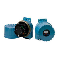
Micro Motion 9739 MVD
Emerson Micro Motion 9739 MVD Manuals
Manuals and User Guides for Emerson Micro Motion 9739 MVD. We have
2
Emerson Micro Motion 9739 MVD manuals available for free PDF download: Configuration And Use Manual
Emerson Micro Motion 9739 MVD Configuration And Use Manual (254 pages)
Brand:
Emerson
| Category:
Transmitter
| Size: 5 MB
Table of Contents
Table of Contents
3
Getting Started
7
Chapter 1 Before You Begin
9
Safety Messages
9
Obtain Version Information
9
Available Communications Tools
9
Additional Documentation and Resources
10
9739 MVD Transmitter Configuration Worksheet
10
Chapter 2 Quick Start with the Display
25
Apply Power
25
Configuration Tips and Tricks
25
Configure the Primary Ma Output to Report Mass Flow Rate in a User-Selected Measurement Unit
26
Perform a Loop Test
27
Zero the Flowmeter
29
Chapter 3 Quick Start with Prolink II
31
Apply Power
31
Connect with Prolink II
31
Configuration Tips and Tricks
46
Configure the Primary Ma Output to Report Mass Flow Rate in a User-Selected Measurement Unit
47
Perform a Loop Test
47
Trim Ma Outputs
49
Zero the Flowmeter
49
Test or Tune the System Using Sensor Simulation
50
Back up Transmitter Configuration
52
Enable/Disable HART Security
53
Chapter 4 Quick Start with the Field Communicator
55
Apply Power
55
Connect with the Field Communicator
55
Configuration Tips and Tricks
58
Configure the Primary Ma Output to Report Mass Flow Rate in a User-Selected Measurement Unit
59
Perform a Loop Test
60
Trim Ma Outputs
61
Zero the Flowmeter
61
Test or Tune the System Using Sensor Simulation
62
Enable/Disable HART Security
64
Reference Information for Commissioning
65
Chapter 5 Configure Process Measurement
67
Characterize the Flowmeter
67
Configure Mass Flow Measurement
70
Configure Volume Flow Measurement for Liquid Applications
75
Configure Gas Standard Volume Flow Measurement
80
Configure Flow Direction
85
Configure Density Measurement
90
Configure Temperature Measurement
94
Configure Pressure Compensation
96
Configure the Petroleum Measurement Application
97
Configure the Concentration Measurement Application
99
Chapter 6 Configure Device Options and Preferences
105
Configure the Transmitter Display
105
Enable or Disable Operator Actions from the Display
109
Configure Security for the Display Menus
111
Configure the Speed of the Transmitter's Response to Changes in Process Data
113
Configure Alarm Handling
114
Configure Informational Parameters
118
Chapter 7 Integrate the Meter with the Control System
123
Configure the Ma Outputs
123
Configure the Frequency Output
130
Configure the Discrete Output
135
Configure the Discrete Input
140
Configure the Ma Input
142
Configure Digital Communications
144
Configure Events
152
Set up Polling for Pressure
154
Set up Polling for Temperature
156
Operations, Maintenance, and Troubleshooting
159
Chapter 8 Transmitter Operation
161
Record the Process Variables
161
View Process Variables
161
View Transmitter Status
163
View and Acknowledge Status Alarms
163
Start and Stop Totalizers and Inventories
167
Reset Mass and Volume Totalizers
168
Reset Mass and Volume Inventories Using Prolink II
169
Chapter 9 Measurement Support
171
Options for Measurement Support
171
Validate the Meter
171
Perform a (Standard) D1 and D2 Density Calibration
174
Perform a D3 and D4 Density Calibration (T-Series Sensors Only)
177
Perform Temperature Calibration
180
Chapter 10 Troubleshooting
183
Transmitter Status LED States
183
Status Alarms
184
Flow Problems
190
Density Problems
193
Temperature Problems
193
Milliamp Output Problems
194
Frequency Output Problems
195
Use Sensor Simulation for Troubleshooting
196
Check Power Supply Wiring
196
Check Sensor-To-Transmitter Wiring
197
Check Grounding
197
Check for Radio Frequency Interference
197
Check HART Communication Loop
198
Check HART Address and Loop Current Mode
198
Check HART Burst Mode
199
Check Ma Output Trim
199
Check Lower Range Value and Upper Range Value
199
Check Ma Output Fault Action
199
Check Frequency Output Mode
199
Check Frequency Output Maximum Pulse Width and Frequency Output Scaling Method
200
Check Frequency Output Fault Action
200
Check Flow Direction
200
Check Cutoffs
200
Check for Slug Flow
201
Check the Drive Gain
201
Check the Pickoff Voltage
203
Check for Electrical Shorts
204
Appendices and Reference
207
Appendix A Default Values and Ranges
209
Default Values and Ranges
209
Appendix B Transmitter Components and Installation Wiring
213
Transmitter Components
213
Transmitter-To-Sensor Wiring
215
Power Supply Terminals
215
Input/Output (I/O) Terminals
216
Appendix C Using the Transmitter Display
219
Components of the Transmitter Interface
219
Access and Use the Display Menu System
221
Display Codes for Process Variables
225
Codes and Abbreviations Used in Display Menus
226
Menu Maps for the Transmitter Display
229
Appendix D Using Prolink II with the 9739 MVD Transmitter
237
Basic Information about the Prolink II Software Tool
237
Menu Maps for Prolink II
238
Appendix E Using the Field Communicator with the 9739 MVD Transmitter
243
Basic Information about the Field Communicator
243
Menu Maps for the Field Communicator
244
Advertisement
Emerson Micro Motion 9739 MVD Configuration And Use Manual (202 pages)
Brand:
Emerson
| Category:
Transmitter
| Size: 2 MB
Table of Contents
Table of Contents
3
About this Manual
7
Before You Begin
7
Related Documentation
7
Supported Protocols
7
Chapter 2 Quick Start
9
Power up the Transmitter
9
Check Meter Status
9
Make a Startup Connection to the Transmitter
10
Characterize the Flowmeter (if Required)
10
Verify Mass Flow Measurement
13
Verify the Zero
14
Introduction to Configuration and Commissioning
17
Configuration Flowchart
17
Default Values and Ranges
18
Enable Access to the Off-Line Menu of the Display
18
Disable Write-Protection on the Transmitter Configuration
18
Disable HART Security
18
Restore the Factory Configuration
19
Configure Process Measurement
21
Configure Mass Flow Measurement
21
Configure Volume Flow Measurement for Liquid Applications
25
Configure GSV Flow Measurement
30
Configure Flow Direction
34
Configure Density Measurement
39
Configure Temperature Measurement
43
Configure the Petroleum Measurement Application
45
Set up Concentration Measurement
50
Configure Pressure Compensation
56
Configure Device Options and Preferences
61
Configure the Transmitter Display
61
Enable or Disable Operator Actions from the Display
64
Configure Security for the Display Menus
66
Configure Response Time Parameters
67
Configure Alert Handling
69
Configure Informational Parameters
72
Integrate the Meter with the Control System
75
Configure the Ma Output
75
Configure the Frequency Output
80
Configure the Discrete Output
84
Configure the Discrete Input
89
Configure the Ma Input
91
Configure Events
93
Configure Digital Communications
94
Set up Polling for Temperature
103
Set up Polling for Pressure
104
Complete the Configuration
107
Back up Transmitter Configuration
107
Enable HART Security
107
Enable Write-Protection on the Transmitter Configuration
108
Chapter 8 Transmitter Operation
109
Record the Process Variables
109
View Process Variables
109
View Transmitter Status Using the Status LED
111
View and Acknowledge Status Alerts
112
Read Totalizer and Inventory Values
116
Start and Stop Totalizers and Inventories
116
Reset Totalizers
117
Reset Inventories
119
Chapter 9 Measurement Support
121
Options for Measurement Support
121
Zero the Meter
121
Validate the Meter
122
Perform a (Standard) D1 and D2 Density Calibration
124
Perform a D3 and D4 Density Calibration (T-Series Sensors Only)
126
Perform Temperature Calibration
129
Chapter 10 Troubleshooting
133
Transmitter Status Reported by LED
133
Check the Cutoffs
133
Density Measurement Problems
134
Check the Drive Gain
135
Check for Internal Electrical Problems
136
Check Flow Direction
138
Flow Measurement Problems
138
Frequency Output Problems
141
Check Frequency Output Fault Action
141
Check Frequency Output Scaling Method
142
Check Grounding
142
Check HART Address and Ma Output Action
142
Check HART Burst Mode
142
Check the HART Communication Loop
143
Locate a Device Using the HART 7 Squawk Feature
143
Perform Loop Tests
144
Check Lower Range Value and Upper Range Value
148
Milliamp Output Problems
148
Check Ma Output Fault Action
150
Trim Ma Output
150
Check the Pickoff Voltage
151
Check Power Supply Wiring
153
Check for Radio Frequency Interference (RFI)
153
Using Sensor Simulation for Troubleshooting
154
Status Alerts, Causes, and Recommendations
154
Check Sensor-To-Transmitter Wiring
169
Check for Two-Phase Flow (Slug Flow)
169
Temperature Measurement Problems
170
Appendix A Using the Transmitter Display
171
Components of the Transmitter Interface
171
Use the Optical Switches
172
Access and Use the Display Menu System
173
Display Codes for Process Variables
176
Codes and Abbreviations Used in Display Menus
178
Appendix B Using Prolink III with the Transmitter
181
Basic Information about Prolink III
181
Connect with Prolink III
182
Appendix C Using a Field Communicator with the Transmitter
187
Basic Information about the Field Communicator
187
Connect with the Field Communicator
188
Appendix D Default Values and Ranges
193
Default Values and Ranges
193
Appendix E Transmitter Components and Installation Wiring
199
Input/Output (I/O) Terminals
199
Advertisement
Related Products
Emerson Micro Motion Transmitters and Discrete Controllers Series 3000
Emerson Micro Motion
Emerson Micro Motion ELITE
Emerson Micro Motion 3300
Emerson Micro Motion 2500
Emerson Micro Motion 2000 Series
Emerson Micro Motion 4200
Emerson Micro-Motion 2400S
Emerson Micro Motion 2400S
Emerson Micro Motion IFT9701
Emerson Categories
Controller
Control Unit
Transmitter
Measuring Instruments
Fan
More Emerson Manuals
Login
Sign In
OR
Sign in with Facebook
Sign in with Google
Upload manual
Upload from disk
Upload from URL