Sign In
Upload
Manuals
Brands
Emerson Manuals
Transmitter
Micro Motion 2400S
Emerson Micro Motion 2400S Manuals
Manuals and User Guides for Emerson Micro Motion 2400S. We have
4
Emerson Micro Motion 2400S manuals available for free PDF download: Configuration And Use Manual, Installation Manual, Product Data Sheet
Emerson Micro Motion 2400S Configuration And Use Manual (188 pages)
Transmitter for DeviceNet
Brand:
Emerson
| Category:
Transmitter
| Size: 2.66 MB
Table of Contents
Table of Contents
3
Chapter 1 Before You Begin
9
Overview
9
Safety
9
Determining Transmitter Information
9
Devicenet Functionality
10
Determining Version Information
10
Communication Tools
10
Planning the Configuration
11
Pre-Configuration Worksheet
12
Flowmeter Documentation
13
Micro Motion Customer Service
14
Chapter 2 Flowmeter Startup
15
Overview
15
Setting the Devicenet Node Address and Baud Rate
15
Bringing the Transmitter Online
15
Using the Transmitter User Interface
17
Overview
17
User Interface Without or with Display
17
Removing and Replacing the Transmitter Housing Cover
19
Using the Optical Switches
19
Using the Display
20
Display Language
20
Viewing Process Variables
20
Using Display Menus
21
Display Password
22
Entering Floating-Point Values with the Display
22
Connecting with Prolink II or Pocket Prolink Software
25
Overview
25
Requirements
25
Configuration Upload/Download
25
Connecting to a Model 2400S DN Transmitter
26
Connection Options
26
Service Port Connection Parameters
26
Connecting Via the Service Port Clips
26
Connecting Via the Irda Port
28
Prolink II Language
28
Chapter 5 Using a Devicenet Tool
29
Overview
29
Connecting to the Model 2400S DN Transmitter
29
Using the Devicenet Device Profile
29
Using a Devicenet Tool
30
Type a Tools
30
Type B Tools
30
Default Assemblies
31
Required Transmitter Configuration
33
Overview
33
Characterizing the Flowmeter
33
When to Characterize
33
Characterization Parameters
33
How to Characterize
35
Configuring the Measurement Units
36
Mass Flow Units
38
Volume Flow Units
38
Density Units
40
Temperature Units
41
Pressure Units
41
Using the Transmitter
43
Overview
43
Recording Process Variables
43
Viewing Process Variables
44
With the Display
44
With Prolink II
44
With a Devicenet Tool
45
Using the Leds
49
Using the Module LED
49
Using the Network LED
50
Viewing Transmitter Status
50
Using the Status LED
50
Using Prolink II
51
Using a Devicenet Tool
51
Handling Status Alarms
51
Using the Display
52
Using Prolink II
53
Using a Devicenet Tool
54
Using the Totalizers and Inventories
55
Viewing Current Values for Totalizers and Inventories
56
Controlling Totalizers and Inventories
57
Optional Configuration
63
Overview
63
Configuring Volume Flow Measurement for Gas
64
Using Prolink II
65
Using a Devicenet Tool
66
Configuring Cutoffs
66
Cutoffs and Volume Flow
67
Configuring the Damping Values
67
Damping and Volume Measurement
68
Configuring the Flow Direction Parameter
68
Configuring Events
69
Defining Events
69
Checking and Reporting Event Status
72
Configuring Slug Flow Limits and Duration
72
Changing Event Setpoints from the Display
72
Configuring Status Alarm Severity
73
Configuring the Display
75
Update Period
75
Language
75
Enabling and Disabling Display Functions
75
Configuring the LCD Backlight
76
Configuring the Display Variables and Display Precision
77
Configuring Digital Communications
78
Devicenet Node Address
78
Devicenet Baud Rate
79
Devicenet Configurable Input Assembly
79
Modbus Address
80
Modbus ASCII Support
80
Irda Port Usage
81
Digital Communications Fault Action
81
Fault Timeout
82
Configuring Device Settings
82
Configuring Sensor Parameters
83
Configuring the Petroleum Measurement Application
83
About the Petroleum Measurement Application
83
Configuration Procedure
85
Configuring the Enhanced Density Application
86
About the Enhanced Density Application
86
Configuration Procedure
88
Chapter 9 Pressure Compensation and Temperature Compensation
91
Overview
91
Pressure Compensation
91
Options
91
Pressure Correction Factors
92
Configuration
92
External Temperature Compensation
93
Obtaining External Pressure and Temperature Data
95
Chapter 10 Measurement Performance
97
Overview
97
Meter Validation, Meter Verification, and Calibration
97
Meter Verification
98
Meter Validation and Meter Factors
98
Calibration
98
Comparison and Recommendations
99
Performing Meter Verification
99
Uncertainty Limit and Test Results
104
Additional Prolink II Tools for Meter Verification
105
Performing Meter Validation
105
Performing Zero Calibration
107
Preparing for Zero
108
Zero Procedure
108
Performing Density Calibration
111
Preparing for Density Calibration
112
Density Calibration Procedures
112
Performing Temperature Calibration
117
Chapter 11 Troubleshooting
119
Overview
119
Guide to Troubleshooting Topics
119
Micro Motion Customer Service
120
Transmitter Does Not Operate
120
Transmitter Does Not Communicate
120
Checking the Communication Device
121
Diagnosing Wiring Problems
121
Checking the Devicenet Cable and Connector
121
Checking Grounding
122
Zero or Calibration Failure
122
Fault Conditions
122
11.10 Simulation Mode for Process Variables
122
11.11 Transmitter Leds
123
11.12 Status Alarms
124
11.13 Checking Process Variables
127
11.14 Checking Slug Flow
129
11.15 Checking the Sensor Tubes
130
11.16 Checking the Flow Measurement Configuration
130
11.17 Checking the Characterization
130
11.18 Checking the Calibration
130
11.19 Checking the Test Points
130
Obtaining the Test Point Values
131
Evaluating the Test Points
131
Drive Gain Problems
132
Low Pickoff Voltage
132
11.20 Checking Sensor Circuitry
133
Appendix A Default Values and Ranges
139
Overview
139
Most Frequently Used Defaults and Ranges
139
Appendix B Menu Flowcharts
143
Overview
143
Version Information
143
Appendix C Device Profile
151
Overview
151
Analog Input Point Object (0X0A)
152
Gas Standard Volume Object (0X64)
154
Calibration Object (0X65)
155
Diagnostics Object (0X66)
157
Sensor Information Object (0X67)
167
Local Display Object (0X68)
168
API Object (0X69)
170
Enhanced Density Object (0X6A)
171
Totalizer and Inventory Measurement Unit Codes
173
Process Variable Codes
174
Alarm Index Codes
175
Appendix D Display Codes and Abbreviations
177
Overview
177
Codes and Abbreviations
177
Index
181
Advertisement
Emerson Micro Motion 2400S Installation Manual (44 pages)
Emerson Satellite Radio User Manual
Brand:
Emerson
| Category:
Transmitter
| Size: 2.41 MB
Table of Contents
Table of Contents
3
Chapter 1 Before You Begin
5
Overview
5
Safety
5
Flowmeter Components
5
Transmitter Installation Overview
6
Flowmeter Documentation
6
Customer Service
7
Chapter 2 Transmitter Orientation and Power Supply
9
Overview
9
Moisture Protection
9
Rotating the Transmitter on the Sensor (Optional)
9
Rotating the User Interface Module on the Transmitter (Optional)
10
Power Supply Requirements
11
DC Power Requirements for Model 2400S Analog and PROFIBUS-DP Transmitters
12
Wiring the Power Supply
12
Chapter 3 I/O Wiring - Model 2400S Analog Transmitters
15
Overview
15
Moisture Protection
15
I/O Options
15
Wiring the Outputs
16
Ma Output Wiring
16
Frequency Output Wiring
20
Discrete Output Wiring
21
Discrete Input Wiring
23
Chapter 4 I/O Wiring - Model 2400S PROFIBUS-DP and Devicenet Transmitters
25
Overview
25
Moisture Protection
25
I/O Wiring for Model 2400S PROFIBUS-DP Transmitters
25
Enabling Internal Termination
26
I/O Wiring for Model 2400S Devicenet Transmitters
27
Appendix A Dimensions and Specifications
29
Dimensions
29
A.1 Dimensions
29
Physical Specifications
31
A.2 Physical Specifications
31
Power Supply - Models 2400S Analog and PROFIBUS-DP
31
Electrical Connections
32
A.4 Electrical Connections
32
User Interface
33
A.5 User Interface
33
Input/Output Signals
35
Digital Communications
36
Host Interface
36
A.7 Digital Communications
36
A.8 Host Interface
36
Environmental Limits
37
Environmental Effects
37
A.9 Environmental Limits
37
A.10 Environmental Effects
37
Hazardous Area Classifications
37
Appendix B Return Policy
39
New and Unused Equipment
39
Used Equipment
39
B.2 Used Equipment
39
Index
41
Emerson Micro Motion 2400S Installation Manual (42 pages)
Brand:
Emerson
| Category:
Transmitter
| Size: 2.91 MB
Table of Contents
Table of Contents
3
Chapter 1 Before You Begin
5
Safety
5
Flowmeter Components
5
Transmitter Installation Overview
6
Flowmeter Documentation
7
Chapter 2 Transmitter Orientation and Power Supply
9
Moisture Protection
9
Rotating the Transmitter on the Sensor (Optional)
9
Rotating the User Interface Module on the Transmitter (Optional)
10
Power Supply Requirements
12
DC Power Requirements for Model 2400S Analog and PROFIBUS-DP Transmitters
12
Wire the Power Supply
13
Chapter 3 Analog Transmitter I/O Wiring
15
Moisture Protection
15
I/O Options
15
Wire the Outputs
16
Chapter 4 I/O Wiring for Model 2400S PROFIBUS-DP and Devicenet Transmitters
27
Moisture Protection
27
I/O Wiring for Model 2400S PROFIBUS-DP Transmitters
27
I/O Wiring for Model 2400S Devicenet Transmitters
29
Appendix A Dimensions and Specifications
31
Dimensions
31
Physical Specifications
33
Power Supply for Models 2400S Analog and PROFIBUS-DP
33
Electrical Connections
34
User Interface
35
Input/Output Signals
37
Digital Communications
38
Host Interface
38
Environmental Limits
39
Environmental Effects
39
Hazardous Area Classifications
39
Appendix B Return Policy
41
New and Unused Equipment
41
Used Equipment
41
Advertisement
Emerson Micro Motion 2400S Product Data Sheet (28 pages)
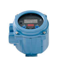
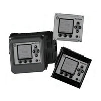
Micro Motion 3000 Series Transmitters and Discrete Controllers
Brand:
Emerson
| Category:
Transmitter
| Size: 0.91 MB
Table of Contents
Table of Contents
3
Housings
4
Applications
4
Interface/Display
5
Electrical Connections
5
Input Signals
6
Output Signals
6
Environmental Specifications
8
Power Supply
8
Hazardous Area Classifications
9
Model 3100 Accessory
10
Model 3500/3700 Liquid Flow Performance
10
Model 3500/3700 Density Performance (Liquid Only)
11
Model 3500/3700 Gas Flow Performance
11
Weight
11
Dimensions
12
Ordering Information
16
Advertisement
Related Products
Emerson Rosemount 248
Emerson Micro Motion 2400S DN
Emerson Rosemount 2051
Emerson Rosemount 2051CF series
Emerson Rosemount 2088
Emerson Rosemount 2090F
Emerson Rosemount 2090P
Emerson Rosemount 2240S
Emerson Rosemount 2051HT
Emerson Rosemount 2051T
Emerson Categories
Controller
Control Unit
Transmitter
Measuring Instruments
Fan
More Emerson Manuals
Login
Sign In
OR
Sign in with Facebook
Sign in with Google
Upload manual
Upload from disk
Upload from URL