Emerson Micro Motion 4200 - 2-Wire Transmitter Manual
- Configuration and use manual (224 pages) ,
- Installation manual (40 pages) ,
- Instruction manual (40 pages)
Advertisement
- 1 Return policy
- 2 Planning
-
3
Mounting and sensor wiring
- 3.1 Mounting and sensor wiring for integral-mount transmitters
- 3.2 Mount the device to a wall or instrument pole
- 3.3 Wire the 9-wire remote-mount unit to the sensor
- 3.4 Ground the meter components
- 3.5 Rotating the unit on the sensor (optional)
- 3.6 Rotating the display orientation
- 3.7 Rotate the sensor wiring junction box on a remote-mount transmitter (optional)
- 4 Wiring the channels
- 5 Powering up the device
- 6 Configuring the unit with Guided Setup
- 7 Using the display controls
- 8 Communicating with the unit
- 9 Documents / Resources
![]()
Return policy
Follow Emerson procedures when returning equipment. These procedures ensure legal compliance with government transportation agencies and help provide a safe working environment for Emerson employees. If you fail to follow Emerson procedures, then Emerson will not accept your returned equipment.
Return procedures and forms are available on our web support site at Emerson.com, or by calling the Micro Motion Customer Service department.
Planning
Meter components
A 4200 meter consists of the following components:
- A transmitter
- A sensor
Installation types
The 4200 transmitter was ordered and shipped for one of two installation types. The fifth character of the transmitter number indicates the installation type.

Installation type indication for 4200 transmitters
The number is located on the device tag on the side of the transmitter.
| Installation types for 4200 transmitters | |
| Code | Description |
| I | Integral mount painted aluminum |
| C | Remote mount painted aluminum |
| J | Integral mount stainless steel |
| P | Remote mount stainless steel |

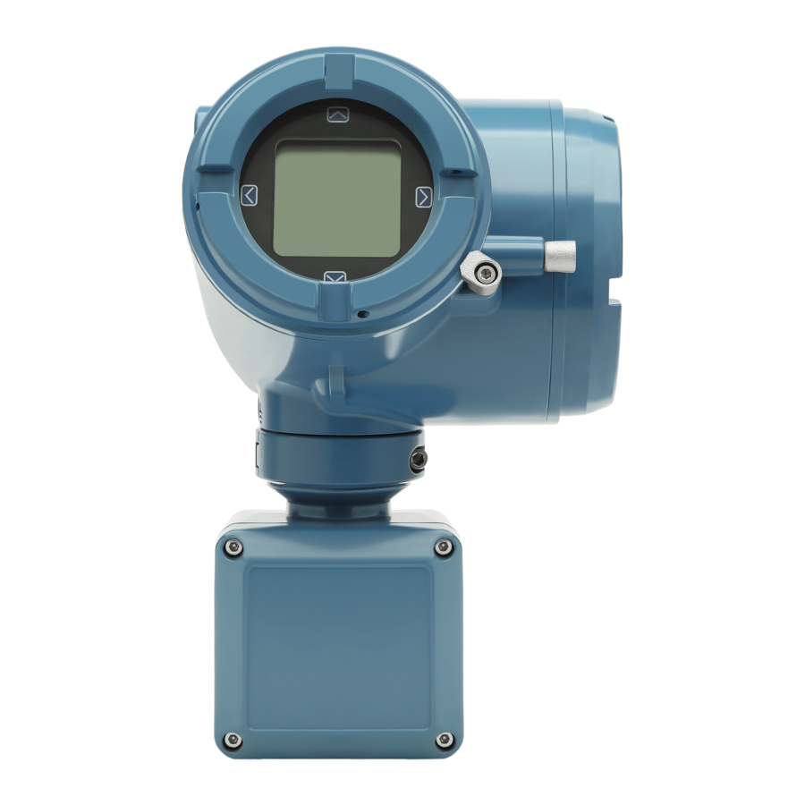
4200 transmitter painted aluminum -- Integral mount
- Conduit openings
- Clamping ring
- Sensor case
- Transmitter housing cover (hidden from view)
The transmitter is installed directly on the sensor.
The connections between the transmitter and sensor are 9-wire, and do not require field wiring on the integral mount version.
The I/O connections consist of two channels, each channel being 2-wire. Power must be supplied to Channel A for the transmitter to operate, while Channel B connections are optional.

4200 transmitter stainless steel -- Integral mount
- Clamping ring
- Junction box
The transmitter is installed remotely from the sensor. The 9-wire connection between the sensor and transmitter must be field wired. Power supply and I/O must be field wired to the transmitter. The sensor connection is in the junction box.
Installation checklist
- Safety messages are provided throughout this content to protect personnel and equipment. Read each safety message carefully before proceeding to the next step.
- When choosing a location for components, refer to the following guidelines:
- See the sensor installation manual for information on locating the sensor with remote-mount or extended-mount electronics.
- Do not install a component in a location where its temperature, humidity, or vibration limits will be exceeded.
- Maximum distance between components depends on the wire size, the wire type, and the power supply. Ensure that sufficient power is supplied to the transmitter terminals.
- If you plan to mount the transmitter in a hazardous area:
- Verify that the transmitter has the appropriate hazardous area approval. Each transmitter has a hazardous area approval tag attached to the transmitter housing.
- Ensure that any cable used between the transmitter and the sensor meets the hazardous area requirements.
- Verify that you have the appropriate cable and required cable installation parts for your installation. For wiring between the transmitter and sensor, verify the maximum cable length does not exceed 60 ft (20 m).
- The transmitter can be mounted in any orientation as long as the conduit openings do not point upward.
![]()
Installing the transmitter with the conduit openings or transmitter display facing upward risks condensation moisture entering the transmitter housing, which could damage the transmitter. - Any fittings, adapters, or blanking elements used on either conduit entries or threaded joints that are a part of flame proof joints must comply with the requirements of EN/IEC 60079-1 & 60079-14 or CSA C22.2 No 30 & UL 1203 for Europe/International and North America respectively.
Only qualified personnel can select and install these elements in accordance with EN/IEC 60079-14 for ATEX/IECEx or to NEC/CEC for North America. - To prevent conduit connectors from seizing in the threads of the conduit openings, apply a conductive anti-galling compound to the threads, or wrap threads with PTFE tape a minimum of two wraps per standard installation practices.
Wrap the tape in the opposite direction that the male threads will turn when inserted into the female conduit opening. - To maintain the Ingress protection thread sealant, a sealing washer, or O-ring must be applied.
- For Zone 1 applications thread sealant must also comply with the requirements of EN/IEC 60079-14 and thus must be non-setting, non-metallic, non-combustible, and maintain earthing between the equipment and conduit.
- For Class I, Groups A, B, C, and D applications thread sealant must also comply with the requirements of UL 1203/CSA C22.2 No. 30.
- Minimize the amount of moisture or condensation inside the transmitter housing. Moisture inside the transmitter housing can damage the transmitter and cause measurement error or flow meter failure. To do this:
- Ensure the integrity of all gaskets and O-rings
- Install drip legs on conduit or cable
- Seal unused conduit openings
- Ensure that all covers are fully tightened
- Mount the meter in a location and orientation that satisfies the following conditions:
- Allows sufficient clearance to open the transmitter housing cover. Install with 8–10 inches (200–250 mm) clearance at the wiring access points.
- Provides clear access for installing cabling to the transmitter.
- Provides clear access to all wiring terminals for troubleshooting.
Maximum cable lengths between sensor and transmitter
The maximum cable length between the sensor and transmitter that are separately installed is determined by cable type.
| Cable type | Wire gauge | Maximum length |
| Micro Motion 9-wire remote mount | Not applicable | 60 ft (18 m) |
Mounting and sensor wiring
Mounting and sensor wiring for integral-mount transmitters
There are no separate mounting requirements for integral transmitters, and there is no need to connect wiring between the transmitter and the sensor.
Mount the device to a wall or instrument pole
There are two options available for mounting the transmitter:
- Mount the transmitter to a wall or flat surface.
- Mount the transmitter to an instrument pole.
Prerequisites
- If you are mounting the transmitter to a wall or flat surface:
- Ensure that the surface is flat and rigid and that it does not vibrate or move excessively.
- Confirm that you have the necessary tools and the mounting kit shipped with the transmitter.
- Confirm that the mounting surface, method, and surface structure ensures sufficient strength to secure the transmitter (e.g. when mounting to drywall use a toggle type drywall anchor).
- If you are mounting the transmitter to an instrument pole:
- Ensure that the instrument pole extends at least 12 in (305 mm) from a rigid base, and is no more than 2 in (51 mm) in diameter.
- Confirm that you have the necessary tools, and the instrument-pole mounting kit shipped with the transmitter.
Procedure
- Attach the mounting bracket to the transmitter and tighten the screws.

Mounting bracket to a painted aluminum transmitter

Mounting bracket to a stainless steel transmitter - Using a wall-mount or pole-mount:


- For wall-mount installations, secure the mounting bracket to the prepared surface.
![]()
Wall-mounting bracket dimensions for a painted aluminum transmitter

- 2.8 in (71.4 mm)
- 2.8 in (71.4 mm)
- For pole-mount installations, attach the U-bolt mounting piece to the instrument pole.

Pole-mounting bracket attachment for a painted aluminum transmitter

Pole-mounting bracket attachment for a stainless steel transmitter


- Place and attach the transmitter-mounting bracket to the mounting bracket secured to the wall or instrument pole.

Attaching and securing a painted aluminum transmitter to mounting bracket
Tip
To ensure the mounting bracket holes are aligned, insert all attachment bolts into place before tightening.

Attaching and securing a stainless steel transmitter to mounting bracket


Wire the 9-wire remote-mount unit to the sensor
Prerequisites
- Prepare 9-wire cable as described in the sensor documentation.
- Connect the cable to the sensor-mounted junction box as described in the sensor documentation.
Procedure
- Remove the transmitter-to-sensor wiring compartment cover to reveal the terminal connections.
![]()
Removal of the transmitter-to-sensor wiring compartment cover - Feed the sensor wiring cable into the transmitter wiring compartment.

Sensor wiring feedthrough - Connect the sensor wires to the appropriate terminals.

9-wire transmitter-to-sensor wiring connections


Note
Connect the 4 drain wires in the 9-wire cable to the ground screw located inside the junction box.
- Replace the transmitter-to-sensor wiring compartment cover and tighten the screws to 14-16 in-lbs.
Ground the meter components
In 9-wire remote installations, the transmitter and sensor are grounded separately.
Prerequisites
NOTICE
Improper grounding could cause inaccurate measurements or meter failure.

Failure to comply with requirements for intrinsic safety in a hazardous area could result in an explosion causing death or serious injury.
Note
For hazardous area installations in Europe, refer to standard EN 60079-14 or national standards.
If national standards are not in effect, adhere to the following guidelines for grounding:
- Use copper wire, 14 AWG (2.08 mm2) or larger wire size.
- Keep all ground leads as short as possible, less than 1 Ω impedance.
- Connect ground leads directly to earth, or follow plant standards.
Procedure
- Ground the sensor according to the instructions in the sensor documentation.
- Ground the transmitter according to applicable local standards, using thetransmitter's internal or external ground screw.
- The earth ground terminal is located inside the power wiring compartment.
- The external ground screw is located on the side of the transmitter located below the transmitter tag.
Rotating the unit on the sensor (optional)
For easier access to the user interface or the wiring terminals, the transmitter can be rotated on the sensor in 45° increments, for eight different orientations.
Procedure
- Remove the metal clamping ring from the base of the feed through.

Rotating the transmitter on the sensor- Clamping ring
- If the transmitter consists of painted aluminum, do the following:
- Gently lift the transmitter on the feed through until it disengages from thenotches on the feed through. You will not be able to remove the transmitter completely.
- Rotate the transmitter to the desired position.
![]()
Do not rotate the housing more than 360°. Excessive rotation can damage the wiring and cause measurement error or flow meter failure. - Lower the transmitter, sliding it onto the notches on the feedthrough.
- Replace the clamping ring on the feed through. Tighten the screw to 28 in lbf(3.16 N m)– 32 in lbf (3.62 N m).


Ensure that the connection between the transmitter and the sensor is moisture-proof. Inspect and grease all gaskets and O-rings. Moisture in the electronics can cause measurement error or flow meter failure.
- If the transmitter consists of stainless steel, do the following:
- Rotate the transmitter to the desired position.
Do not rotate the housing more than 360°. Excessive rotation can damage the wiring and cause measurement error or flow meter failure.
- Lower the transmitter, sliding it onto the notches on the feedthrough.
- Replace the clamping ring on the feed through. Tighten the screw to 28 in lbf (3.16 N m) – 32 in lbf (3.62 N m).
Ensure that the connection between the transmitter and the sensor is moisture-proof. Inspect and grease all gaskets and O-rings. Moisture in the electronics can cause measurement error or flow meter failure.
Rotating the display orientation
The user interface orientation for the transmitter can rotate 360° in 90° increments by software selection.
Using the display, select Menu  Configuration Display Settings Rotation.

Rotate the sensor wiring junction box on a remote-mount transmitter (optional)
In remote-mount installations, you can rotate the sensor wiring junction box on the transmitter up to plus or minus 180 degrees.
Procedure
- Using a 4 mm hex key, loosen and remove the clamp securing the sensor wiring junction box in place.
- Gently rotate the junction box to the desired position.
You can rotate the junction box plus or minus 180º to any position.

Removal of the clamp

Rotation of the sensor wiring junction box - Gently set the junction box into its new position, confirming that the position islocked.
- Replace the clamp in its original position and tighten the cap screw. Tighten the screw to 28 in lbf (3.16 N m)– 32 in lbf (3.62 N m).

Re-attachment of the clamp


Wiring the channels
Installation types for the unit
Improper installation in a hazardous area can cause an explosion.
General configuration

- 2-wire cable power and signal
- 4-20 mA
- mA receiving device
- HART variables
- DCS
- Emerson AMS Trex communicator
Connection example for cases where a barrier is required

- Hazardous area
- Safe area
- 2-wire cable power and signal
- Barrier
- 4-20 mA
- mA receiving device
- HART variables
- DCS
- Emerson AMS Trex communicator
Available channels
| Signal | Channel A | Channel B | ||
| Wiring terminals | 1 | 2 | 3 | 4 |
| mA outputs | 4-20mA Loop Powered (HART) | (Optional licensed channel) Configurable as passive 4-20mA / Frequency Output / Discrete Output | ||
Note
Remember when using the second configurable output (Channel B), all power to the electronics is still supplied over the primary 4 - 20 mA signal wiring (Channel A).
Barriers verified by Micro Motion
The following table lists the barriers that Micro Motion has verified with the 4200 transmitter. For other barriers, refer to the manufacturer's data sheet.
| Barriers verified by Micro Motion | |
| Vendor | Barrier |
| Micro Motion | 505 |
| Pepperl & Fuchs | KFD2-STC1-EX1 |
| Pepperl & Fuchs | KFD2-STC4-EX1 |
| MTL | 787S+ |
| MTL | 7707P+ |
| MTL | 7787+ |
| MTL | 5042 |
| MTL | 3046B |
| MTL | 7728P+ |
| MTL | 4541 |
| STAHL | 9002/13-280-110-00 |
| PR Electronics | 5106 |
Channel power requirements
The supply voltage required by the 4200 transmitter depends on the total resistance in the mA loop. This includes all sense resistance and wire resistance.
Channel A mA HART terminal requirements
Use the chart below to determine the required supply voltage for Channel A based on loop resistance.

Figure 3-1: Channel A output supply voltage and loop resistance
- Loop resistance (Ohms)
- Supply voltage (Vs)
- Maximum Loop Resistance (Ohms)
| For maximum loop resistance for Channel A | |
| Condition | Equation |
| 17.75V < Vs < 19.6V | (Vs-17.75)/3.6mA |
| 19.6V < Vs < 21.5V | (Vs-8.32V)/22mA |
| 21.5V < Vs < 30V | 600 ohms |
Note
If display backlighting is enabled (refer to Configure the display backlight), the minimum input voltage required is 1V higher than the chart indicates.
Channel B mA terminal requirements
Use the following chart to determine the required supply voltage for Channel B mA based on loop resistance.
Note
Remember when using the second configurable output (Channel B), all power to the electronics is still supplied over the primary 4 - 20 mA signal wiring (Channel A).

Figure 3-2: Channel B output supply voltage and loop resistance
- Loop resistance (Ohms)
- Supply voltage (Vs)
- Maximum Loop Resistance (Ohms)
| For maximum loop resistance for Channel B | |
| Condition | Equation |
| 7.0V < Vs <20.2V | (Vs-7.0V)/22mA |
| 20.2V < Vs < 30V | 600 ohms |
Channel B DO/FO terminal requirements
Use the chart below to determine the required supply voltage for Channel B for DO/FO.

Figure 3-3: Channel B FO/DO output supply voltage and loop resistance
- Loop resistance (Ohms)
- Supply voltage (Vs)
- Maximum Loop Resistance (Ohms)
Note
For Maximum Loop Resistance:
- (Vs – 6.0V)/4.0mA.
Channel B DO/FO high and low voltages for nonhazardous installations

Output high and low voltages
- Output voltage (V)
- Load resistance (Ohm)
- Low voltage
- High voltage
- Voltage (volts)
- Time
High and low voltage equations
High voltage ≈ (Vsupply – 1.08V) * RL/(1130 + RL)
Low voltage ≈ 0.0002*RL
Access the wiring channels
Procedure
- Remove the wiring access cover to reveal the I/O wiring terminal block connectors.
![]()
Channels on the Transmitter Terminal - Confirm which transmitter channels are activated, or ON, and identify the type of configuration you will be wiring to based on the options available.
![]()
Activated channel identification - (Recommended) Record the channel and wiring configuration on the label provided inside the transmitter housing cover.

Channel and wiring configurations label


Wire the Channel A mA HART output
To wire the mA/HART output in explosion-proof, intrinsically safe, or nonhazardous installations, follow this procedure.
Meter installation and wiring should be performed only by suitably-trained personnel using the appropriate government and corporate safety standards.
Procedure
Wire to the appropriate output terminal and pins.

Channel A mA/HART output wiring (externally powered)
- mA HART output
- Supply Voltage (See Figure 3-1.)
- Loop Resistance (See Figure 3-1 for maximum loop resistance.)
- Input device
Wire the Channel B mA output
To wire the mA output in explosion-proof, intrinsically safe, or nonhazardous installations, follow this procedure.
Meter installation and wiring should be performed only by suitably-trained personnel using the appropriate government and corporate safety standards.
Note
Remember when using the second configurable output (Channel B), all power to the electronics is still supplied over the primary 4 - 20 mA signal wiring (Channel A).
Procedure
Wire to the appropriate output terminal and pins.

Channel B mA output wiring (externally powered)
- mA output
- Supply Voltage (See Figure 3-2.)
- Loop Resistance (See Figure 3-2 for maximum loop resistance.)
- Input device
Wire Frequency/Discrete output (Channel B)
Use this procedure to wire the externally-powered Frequency Output or Discrete Output for Channel B.
Meter installation and wiring should be performed only by suitably-trained personnel using the appropriate government and corporate safety standards.
Note
Remember when using the second configurable output (Channel B), all power to the electronics is still supplied over the primary 4 - 20 mA signal wiring (Channel A).
Procedure
Wire to the appropriate output terminal and pins.

Discrete Output wiring (externally powered)
- Frequency/ Discrete Output
- Channel B
- Supply Voltage (See Figure 3-3.)
- Loop Resistance (See Figure 3-3 for maximum loop resistance.)
- Counter or Discrete Output
Powering up the device
The transmitter must be powered up for all configuration and commissioning tasks, or for process measurement.
Procedure
- Ensure that all transmitter and sensor covers and seals are closed.
![]()
To prevent ignition of flammable or combustible atmospheres, ensure that all covers and seals are tightly closed. For hazardous area installations, applying power while housing covers are removed or loose can cause an explosion. - Turn on the electrical power at the power supply.
The transmitter will automatically perform diagnostic routines. During this period, the Warming Up alert is active. The diagnostic routines should complete in approximately 30 seconds.

Postrequisites
Although the sensor is ready to receive process fluid shortly after power-up, the electronics can take up to 10 minutes to reach thermal equilibrium. Therefore, if this is the initial startup, or if power has been off long enough to allow components to reach ambient temperature, allow the electronics to warm up for approximately 10 minutes before relying on process measurements. During this warm-up period, you may observe minor measurement instability or inaccuracy.
Configuring the unit with Guided Setup
At initial startup of the transmitter, click the right arrow for the Menu option to access Guided Setup. This tool guides you through basic configuration of the transmitter. The guided setup allows you to upload configuration files, set the transmitter display options, configure channels, and review sensor calibration data.
Procedure
To access the guided setup screen from the display main menu, go to: Startup Tasks  Guided Setup.
Using the display controls
The transmitter display interface includes a display (LCD panel) and four capacitive buttons – left, up, down, and right arrow keys – used to access the display menus and navigate the display screens.
Procedure
- To activate a capacitive button, press the desired button that is designated with arrows (up, down, left, and right).
You can activate the capacitive button through the lens. Do not remove the transmitter housing cover.
![]()
The transmitter only detects one button selection at a time. Be sure to press your thumb or finger on a single capacitive button.

Proper finger positioning for activating a capacitive button - Use the arrow indicators on the display screen to identify which capacitive button to use to navigate the screen (see examples 1 and 2).
![]()
When using the arrow keys, you must first activate the capacitive button, then release the same button by removing your finger from the glass to move up, down, right, left or to make a selection. To enable auto-scroll when navigating up or down, activate the appropriate button and continue to hold for one second. Release the button when the desired selection is highlighted.

Example 2: Active arrow indicators on the transmitter display


Configure the display backlight
By default, the backlight is set to OFF. The backlight requires an additional 1V in voltage over no backlight.
Procedure
To configure the backlight, select Menu  Configuration Display Settings Backlight.
Communicating with the unit
Use either the HART terminals connected to ProLink III or Trex unit to download or upload data from/to the transmitter, because the service port is for factory use only.
Procedure
- To connect to the transmitter terminals or to the HART connection posts:
- Remove the transmitter end-cap.
- Attach the leads from the Field Communicator to terminals 1 and 2 on thetransmitter, or to the HART connection posts, and add resistance as required. The Field Communicator must be connected across a resistance of 250–600 Ω.
Tip
HART connections are not polarity-sensitive. It does not matter which lead you attach to which terminal.

Field Communicator connection to transmitter terminals- Field Communicator
- 250–600 Ω resistance
- External power supply, if required
- Transmitter with end-cap removed
- HART connection posts
- Factory use only
- Turn on the Field Communicator and wait until the main menu is displayed.

For more information: Emerson.com/global
©2023 Micro Motion, Inc. All rights reserved.
The Emerson logo is a trademark and service mark of Emerson Electric Co. Micro Motion, ELITE, ProLink, MVD and MVD Direct Connect marks are marks of one of the Emerson Automation Solutions family of companies. All other marks are property of their respective owners.

Documents / Resources
References
Download manual
Here you can download full pdf version of manual, it may contain additional safety instructions, warranty information, FCC rules, etc.
Download Emerson Micro Motion 4200 - 2-Wire Transmitter Manual
Advertisement


Need help?
Do you have a question about the Micro Motion 4200 and is the answer not in the manual?
Questions and answers