Sign In
Upload
Manuals
Brands
Eaton Manuals
Control Panel
XV300 Series
Eaton XV300 Series Manuals
Manuals and User Guides for Eaton XV300 Series. We have
3
Eaton XV300 Series manuals available for free PDF download: Manual
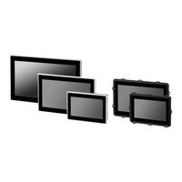
Eaton XV300 Series Manual (123 pages)
Brand:
Eaton
| Category:
Industrial Equipment
| Size: 4.85 MB
Table of Contents
XV300 Manual
1
Imprint
2
Before Commencing the Installation
3
Table of Contents
5
Table of Content
5
Figure 24: Mounting
6
About this Documentation
9
List of Revisions
9
Target Group
10
Legal Disclaimer
11
Device Designations and Abbreviations
11
Writing Conventions
11
Table 1: Format Conventions Used Throughout this Manual
11
Hazard Warnings
12
Documents with Additional Information
13
Description
14
Function
14
Features
14
Options
14
Notes
15
Smartwire-DT
15
Xn300
15
Use as Intended
16
Device Models - Versions and Part Nos
17
Basic Features
17
Device Variants
17
Optional Features
17
Figure 1: Front with Plastic Frame
18
Figure 2: Service Side with Optional Interfaces
18
Figure 3: Front with Plastic Frame
18
Figure 5: Front Side with Aluminum Frame
18
Table 2: Enclosure Versions for Front Mounting
18
Figure 7: Front Side with Aluminum Mounting
19
Figure 8: Service Side with Optional Interfaces
19
Figure 9: Front Side with Aluminum Mounting
19
Figure 10: Service Side with Optional Interfaces
19
Table 3: Enclosure Versions for Rear (Panel)
19
Operating and Indication Elements
20
Overview
20
Figure 4: Service Side with Optional Interfaces
20
Figure 6: Service Side with Optional Interfaces
20
Interfaces to Peripheral Devices
21
Figure 11: Interfaces
21
How to Interpret the Part Number
22
Table 6: Display Size
22
Table 7: Interfaces
22
Table 8: Version
22
Table 9: Bundles with Visualization Software
22
Accessory Devices
23
Indication Label
24
Support
24
Figure 12: Example for a Nameplate
24
Conditions for Underwriters Laboratories Inc. (UL) Listing
25
Marine Approvals
26
Safety Regulations
27
Basics
27
Mandatory Requirements, Personnel Requirements
27
Occupational Safety
27
Personnel Qualifications
27
Device Documentation
27
Installation, Maintenance, and Disposal
28
Prerequisites for Proper Operation
28
Device-Specific Hazards
30
Installation
35
Prerequisites for the Area of Application
35
Installation Position
35
Temperatures
35
Figure 13: Space Required to Remove the SD
35
Aeration and De-Aeration
36
Criteria for the Installation Position
37
Figure 14: Cooling Air Circulation
37
Figure 15: Mounting Distance
37
Figure 16: Mounting Position
38
Technical Conditions for Acceptance by Underwriters Laboratories Inc. (UL)
39
Conditions for Marine Approvals
40
Radio Interference Suppression Filter for the 24 V DC Supply
40
Figure 17: Engineering Example for Integration of Radio Interference Suppression Filters
40
Unpacking and Checking the Equipment Supplied
41
Table 10: Std. Pack
41
Mounting
42
Fixing and Sealing
42
Front Mounting
42
Figure 18: Peripheral Gasket Along the Entire
43
Figure 19: Pre-Installing the Holding Brack- Etsscrew the Set Screwsinternal Hexagon
44
Figure 20: Installing the Holding Brackets
44
Rear (Panel) Mounting Rear (Panel) Mounting
46
Figure 21: M4 X 12 Weld Studs on Sheet
46
Figure 22: Dimensional Drawing for Mounting
46
Figure 23: Dimensional Drawing for Mountingxv-313-10
47
Preparing the Device for Operation
48
Functional Earthing XV300
51
Figure 25: Screwing the Functional Earth con
51
Table 11: Specification Functional Earthing
51
Power Supply - Electrical Connection
52
Figure 26: Connecting the Screw Terminals on
52
Table 12: Configuration Plug Connector MSTB
52
Table 13: Specifications for Connection to
52
Commissioning
54
Initial Commissioning
54
Running the XV300
54
External Connections
56
Layout of Interfaces
57
Optional Interfaces
57
Figure 28: Interfaces Included on All HMI Panels
57
SD Card
58
USB Interfaces
59
USB Host
59
USB Device
59
Ethernet 1, Ethernet
60
Serial Interfaces for Communication with Plcs or Devices
61
Com1
61
Wiring
61
Table 14: Pin Assignment COM1 RS-232, Not Gal
61
Table 15: RS-232 Cable Length Based on Baud
61
Com2
62
Wiring
62
Table 16: Pin Assignment COM2 RS-485, Not Gal
62
Table 17: Specifications for RS-485 Wiring
62
Topology
63
Figure 33: Bus Segment with Four Nodes
63
CAN1 Interface for Protocols Canopen and J1939
64
Wiring
64
Table 18: PIN Assignment for CAN Interface as
64
Table 19: Specifications for CAN Wiring
64
CAN-Bus-Topology
65
Figure 34: CAN Bus Segment with Four Nodes
65
PROFIBUS Interface
66
Wiring
66
Table 20: Pin Assignment for Profibus DP, Not
66
Table 21: Specifications for Profibus Wiring
66
Profibus Topology
67
XV300 Multi Touch Display as Smartwire-DT Coordinator
68
Smartwire-DT Powered Via POW/AUX
68
Figure 36: Smartwire-DT Power Connector
68
SWD Power Supply Voltages
69
Smartwire-DT Interface
70
Table 23: Wiring the Plug Connector
70
Table 24: Overcurrent and Short-Circuit Protective Device Standards
70
Table 25: Pin Assignment for Smartwire-DT Ribbon Cable Interface (Pin Header, 8-Pin)
70
Commissioning the Smartwire-DT Network
71
Table 26: SWD-LED
72
Table 27: Config-LED
72
Faults
74
Maintenance
75
Cleaning and Maintenance
75
Capacitive Multi-Touch Technology (PCT)
75
Battery
75
Repairs
75
Storage, Transport and Disposal
76
Storage and Transport
76
Disposal
77
Table 28: Materials Used XV300
78
Appendix
79
Technical Data
80
Data Sheets
80
Specifications: Dimensions and Weight
80
Mounting Surrounds for Rear (Panel) Mounting
87
Figure 46: Installation Panel for XV-313-70
87
Figure 47: Installation Panel for XV-313-10
87
General Data
88
Specifications: Interfaces
90
Front Mounting
90
Front Mounting with Smartwire-DT Connection
93
Rear (Panel) Mounting
96
Figure 30: USB 2.0, Not Galvanically Isolated
96
Figure 31: USB 2.0, Not Galvanically Isolated
96
Table 5: Type
96
Rear (Panel) Mounting with Smartwire-DT Connection
98
Information on the Power Supply
100
Approvals and Declarations
102
Table 39: Overcurrent and Short-Circuit Protective Device Standards
103
Further Reading
104
Alphabetical Index
107
List of Figures
111
List of Tables
112
Glossary
113
Advertisement
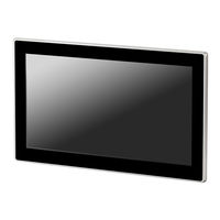
Eaton XV300 Series Manual (103 pages)
Brand:
Eaton
| Category:
Control Panel
| Size: 4.1 MB
Table of Contents
Table of Contents
4
Figure 20: Mounting
5
About this Documentation
8
List of Revisions
8
Target Group
9
Legal Disclaimer
9
Device Designations and Abbreviations
11
Writing Conventions
12
Hazard Warnings
12
Table 1: Format Conventions Used Throughout this Manual
12
Documents with Additional Information
13
1 Description
14
Function
14
Features
14
Options
14
Notes
15
Smartwire-DT
15
Xn300
15
Intended Use
16
Device Models - Versions and Part Nos
17
Basic Features
17
Device Variants
17
Optional Features
17
Figure 1: Front Side with Plastic Bezel
18
Figure 2: Service Side with Optional Interfaces
18
Figure 3: Front Side with Plastic Bezel
18
Figure 4: Service Side with Optional Interfaces
18
Figure 5: Front Side with Aluminum Mounting
18
Figure 7: Front Side with Aluminum Mounting
18
Table 2: Enclosure Versions for Front Mounting
18
Table 3: Enclosure Versions for Rear (Panel)
18
Operator Control and Display Elements
19
Overview
19
Figure 6: Service Side with Optional Interfaces
19
Figure 8: Service Side with Optional Interfaces
19
Interfaces to Peripheral Devices
20
Figure 9: Interfaces
20
Overview of Available Versions
21
Table 4: Front Mounting Versions with a 7.0" Dis
21
Table 5: Versions: Flush Mounting 10.1" Display
21
Table 6: Rear (Panel) Mounting Versions with a
21
Table 7: Rear (Panel) Mounting Versions with a
21
Accessories
22
Designation
23
Nameplate
23
Support
23
Figure 10: Example for a Nameplate
23
2 Safety Instructions
24
Basics
24
Mandatory Requirements, Personnel Requirements
24
Occupational Safety
24
Personnel Qualifications
24
Device Documentation
24
Installation, Maintenance, and Disposal
25
Prerequisites for Proper Operation
25
Device-Specific Hazards
27
3 Installation
31
Prerequisites for the Location of Use
31
Installation Position
31
Temperatures
31
Figure 11: Space Required to Remove the SD
31
Aeration and De-Aeration
32
Figure 12: Cooling Air Circulation
32
Figure 13: Mounting Distance
32
Criteria for the Installation Position
33
Figure 14: Mounting Position
33
Technical Conditions for Acceptance by Underwriters Laboratories Inc. (UL)
34
Unpacking and Checking the Equipment Supplied
35
Table 8: Std. Pack
35
Mounting
36
Fixing and Sealing
36
Front Mounting
37
Figure 15: Pre-Installing the Holding Brack
37
Figure 16: Mounting the
37
Rear (Panel) Mounting
39
Figure 17: M4 X 12 Weld Studs Onto the Sheet
39
Figure 18: Dimensional Drawing for Mount
39
Figure 19: Dimensional Drawing for Mount
40
Preparing the Device for Operation
41
Functional Earthing XV300
43
Figure 21: Screwing the Functional Earth Conductor Onto the Enclosure
43
Table 9: Functional Earthing Specifications
43
Power Supply - Electrical Connection
44
Figure 22: Connecting the Screw Terminals on the Plug Connector MSTB 2.5/3-ST-5.08
44
Figure 23: Power Supplied through Plug con
44
Table 10: Configuration Plug Connector MSTB
44
Table 11: Specifications for Connection to
44
4 Commissioning
46
Initial Commissioning
46
Running the XV300
46
5 External Connections
47
Layout of Interfaces
48
Optional Interfaces
48
Figure 24: Interfaces Included on All HMI Panels
48
Figure 25: XV300 Touch Panel with All Optional
48
SD Card
49
USB Interfaces
50
USB Host
50
USB Device
50
Figure 27: USB 2.0, Not Galvanically Isolated
50
Ethernet 1, Ethernet
51
Figure 28: RJ-45 Socket, 8-Pole, 2 Leds
51
Serial Interfaces for Communication with Plcs or Devices
52
Com1
52
Wiring
52
Table 12: Pin Assignment COM1 RS-232, Not Gal
52
Table 13: RS-232 Cable Length Based on Baud
52
Com2
53
Wiring
53
Table 14: Pin Assignment COM2 RS-485, Not Gal
53
Table 15: Specifications for RS-485 Wiring
53
Topology
54
Figure 29: Bus Segment with Four Nodes
54
CAN1 Interface for the Canopen Protocol, J1939 Protocol, Etc
55
Wiring
55
Table 16: PIN Assignment for CAN Interface as
55
Table 17: Specifications for CAN Wiring
55
CAN-Bus-Topology
56
Figure 30: CAN Bus Segment with Four Nodes
56
Profibus Interface
57
Wiring
57
Table 18: Pin Assignment for Profibus DP, Not
57
Table 19: Specifications for Profibus Wiring
57
Profibus Topology
58
Figure 31: Profibus Bus Segment with Four
58
XV300 Touch Panel as a Smartwire-DT® Coordinator
59
Smartwire-DT® Powered Via POW/AUX
59
Figure 32: Smartwire-DT® Power Connector
59
SWD Power Supply Voltages
60
Smartwire-DT® Interface
61
Table 21: Wiring the Plug Connector
61
Table 22: Overcurrent and Short-Circuit Pro- Tective Device Standards
61
Table 23: Pin Assignment for Smartwire-DT Rib- Bon Cable Interface (Pin Header, 8-Pin)
61
Commissioning the Smartwire-DT® Network
62
6 Interferences
65
7 Maintenance
66
Cleaning and Maintenance
66
Capacitive Multi-Touch Technology (PCT)
66
Battery
66
Repairs
66
Storage, Transport and Disposal
67
Storage and Transport
67
Disposal
68
Table 26: Materials Used XV300
68
Appendix
69
Technical Data
70
Dimension and Weight Specifications
70
Figure 39: Installation Panel for XV-313-70
74
Figure 40: Installation Panel for XV-313-10
74
General Data
75
Port and Interface Specifications
76
Mounting Surrounds for Rear (Panel) Mounting
74
Front Mounting
76
Front Mounting with Smartwire-DT® Connection
78
Rear (Panel) Mounting
80
Information on the Power Supply
82
Approvals and Declarations
85
Table 33: Overcurrent and Short-Circuit Pro- Tective Device Standards
86
Further Reading
87
Alphabetical Index
88
List of Figures
91
List of Tables
92
Glossary
93
Eaton XV300 Series Manual (115 pages)
Brand:
Eaton
| Category:
Recording Equipment
| Size: 1.74 MB
Table of Contents
XV300 Manual
1
Company Information
2
Before Starting with the Installation
3
Table of Contents
5
About this Documentation
9
List of Revisions
9
Target Group
10
Legal Disclaimer
11
Device Designations and Abbreviations
11
Writing Conventions
12
Warning Labels
12
Additional Information for Use
13
Description
14
Function
14
Features
14
Options
14
Notes
15
Smartwire-DT
15
Xn300
15
Use as Intended
16
Device Models - Versions and Part Nos
17
Basic Features
17
Device Variants
17
Optional Features
17
Operating and Indication Elements
20
Interfaces to Peripheral Devices
21
What the Different Parts of the Part Number Mean
22
Accessory Devices
24
Nameplate
25
Support
26
Conditions for Underwriters Laboratories Inc. (UL) Listing
27
Marine Approvals
28
Safety Regulations
29
Basics
29
Mandatory Requirements, Personnel Requirements
30
Occupational Safety
30
Personnel Qualifications
30
Device Documentation
30
Installation, Maintenance, and Disposal
30
Prerequisites for Proper Operation
31
Device-Specific Hazards
32
Installation
37
Prerequisites for the Location of Use
37
Installation Position
37
Temperatures
37
Aeration and De-Aeration
38
Criteria for the Installation Position
39
Technical Conditions for Acceptance by Underwriters Laboratories Inc. (UL)
41
Conditions for Marine Approval
42
Radio Interference Suppression Filter for the 24-V-DC-Supply
42
Unpacking and Checking the Equipment Supplied
44
Mounting
45
Fixing and Sealing
45
Front Mounting
46
Rear (Wall) Mounting
48
Preparing the Device for Operation
50
Functional Earthing XV300
52
Power Supply - Electrical Connection
53
Commissioning
55
Initial Commissioning
56
Running the XV300
57
External Connections
58
Layout of Interfaces
59
Optional Interfaces
60
SD Card
61
USB Interfaces
62
USB Host
62
USB Device
62
Ethernet 1, Ethernet
63
Serial Interfaces for Communication with Plcs or Devices
64
Com1
64
Wiring Topic
64
Com2
65
CAN1 Interface for the Canopen Protocol, J1939 Protocol, Etc
67
Profibus Interfaces
69
XV300 Multi-Touch Display as a Smartwire-DT Coordinator
71
Smartwire-DT Powered Via POW/AUX
71
SWD Power Supply Voltages
72
Smartwire-DT Interface
74
Commissioning the Smartwire-DT Network
75
Faults
78
Maintenance
79
Cleaning and Maintenance
79
Capacitive Multi-Touch Technology (PCT)
79
Battery
79
Repairs
80
Storage, Transport and Disposal
81
Storage and Transport
81
Disposal
83
Appendix
84
Technical Data
85
Data Sheets
85
Dimension and Weight Specifications
85
Mounting Surrounds for Rear (Panel) Mounting
92
General Data
93
Port and Interface Specifications
95
Front Mounting
95
Front Mounting with Smartwire-DT Connection
98
Rear (Panel) Mounting
101
Rear (Panel) Mounting with Smartwire-DT Connection
103
Information on the Power Supply
105
Approvals and Declarations
107
Further Usage Information
109
Alphabetical Index
111
Advertisement
Advertisement
Related Products
Eaton XV-112
Eaton XV360
Eaton XV400 12.1"
Eaton XV400 10.4"
Eaton XV400 5.7"
Eaton XV400 8.4"
Eaton XVS400
Eaton XV-152 Series
Eaton XV-102 Series
Eaton XV200
Eaton Categories
UPS
Circuit breakers
Industrial Equipment
Switch
Industrial Electrical
More Eaton Manuals
Login
Sign In
OR
Sign in with Facebook
Sign in with Google
Upload manual
Upload from disk
Upload from URL