Sign In
Upload
Manuals
Brands
Danfoss Manuals
Media Converter
iC2-Micro Series
Danfoss iC2-Micro Series Manuals
Manuals and User Guides for Danfoss iC2-Micro Series. We have
1
Danfoss iC2-Micro Series manual available for free PDF download: Design Manual
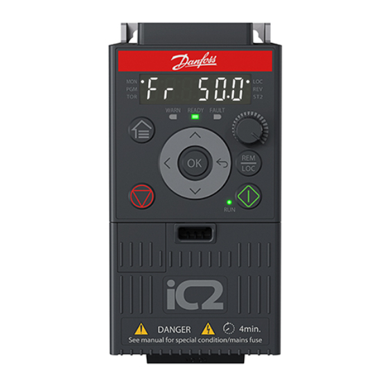
Danfoss iC2-Micro Series Design Manual (104 pages)
Frequency Converters
Brand:
Danfoss
| Category:
Media Converter
| Size: 11 MB
Table of Contents
Table of Contents
3
Introduction and Safety
9
Purpose of this Design Guide
9
Additional Resources
9
Planning and Design Support Materials
9
Version History
9
Safety Symbols
10
Medical Devices
10
General Safety Considerations
10
Qualified Personnel
12
Approvals and Certifications
13
Product Approvals and Certifications
13
Standards
14
Export Control Regulation
15
Ic2-Micro Frequency Converters
16
Intended Use
16
Foreseeable Misuse
16
Block Diagram
16
Ecodesign for Power Drive Systems
17
Overview
17
Power Losses and Efficiency
18
Frequency Converter
18
Power Hardware
19
Control and Interfaces
19
Control Terminals
19
RJ45 Port and RS485 Termination Switch
20
Control Panel and Control Panel 2.0 OP2
21
Control Panel Buttons and Indicators
22
Control Panel 2.0 OP2 Buttons and Indicators
24
Sliding Door on the Terminal Cover
25
Application Software
26
Ic2-Micro Application Software Overview
26
Basic Functions
27
Basic Functions Overview
27
Reference Handling
27
Protection Features
30
Automatic Derating
31
Monitoring Features
31
Monitoring Features Overview
31
Speed Monitoring
31
Event Log and Operational Counters
31
Software Tools
31
Software Tools Overview
31
Mydrive® Select
32
Mydrive® Harmonics
32
Mydrive® Ecosmart
32
Mydrive® Insight
32
Brake Functions
32
Mechanical Holding Brake
32
Dynamic Braking
32
Brake Resistor Selection
33
Introduction
33
Brake Resistance Calculation
33
Danfoss Recommended Brake Resistance Calculation
34
Control with Brake Function
35
Specifications
36
Electrical Data
36
Mains Supply 1X100-120 V AC
36
Mains Supply 1X200-240 V AC
36
Mains Supply 3X200-240 V AC
37
Mains Supply 3X380-480 V AC
38
General Technical Data
39
Protection and Features
39
Grid Side
39
Motor Output and Motor Data
40
Torque Characteristics
40
Control I/O
40
Control I/O Overview
40
Digital and Pulse Input
41
Digital and Pulse Output
41
Analog Input
42
Analog Output
42
Relay Output
43
Auxiliary Voltages
43
RS485 Serial Communication
44
Ambient Conditions
44
Overview of Ambient Conditions
44
Ambient Conditions During Storage
44
Ambient Conditions During Transport
45
Ambient Conditions During Operation
45
Fuses and Circuit Breakers
45
Power Connectors
46
Acoustic Noise
48
EMC Compliance Levels
48
Overview of EMC Compliance Levels
48
Emission Requirements
49
EMC Immunity Requirements
49
EMC Compatibility and Motor Cable Length
51
Du/Dt Conditions
51
Derating
53
Overview of Derating
53
Manual Derating
53
Automatic Derating
56
Exterior Dimensions
57
Ip20/Open Type Enclosure Sizes and Dimensions
57
IP21/UL Type 1 Enclosure Sizes and Dimensions
58
NEMA 1 Enclosure Sizes and Dimensions
59
Mechanical Installation Considerations
60
Contents of the Shipment
60
Product Labels
60
Product Labels Overview
60
Product Labels on Drives
60
Package Labels
61
Recommended Disposal
62
Storage until Installation
62
Reforming the Capacitors
62
Safe Transportation and Storage
63
Prerequisites for Installation
64
Overview of Prerequisites for Installation
64
Operating Environment
64
Maintenance Considerations
65
Regular Maintenance
65
Preventive Maintenance Recommendations
65
Service Access
67
Heat Sink and Fan Maintenance and Service
68
Mechanical Installation
68
Mounting Considerations
68
Mounting Locations
69
Mounting Directions
69
Recommended Screws and Bolts
69
Drilling Patterns
70
Placement of the Drive in the Installation
71
Cooling
71
Recommended Space for Service Access
72
Electrical Installation Considerations
74
Electrical Installation Precautions
74
Wiring Diagram
75
Grid Type and Protection
76
Grid Types
76
Currents on Protective Earth and Potential Equalization/Leakage Currents
76
PE Current Measurement
77
Residual Current Device (RCD) Protection
78
Isolation Monitoring Devices
79
EMC-Compliant Installation
79
EMC-Compliant Installation Guidelines
79
Power Cables and Grounding
81
Control Cables
82
Galvanic Isolation
82
Ground Leakage Current
83
Motor Installation
85
Motor Installation Considerations
85
Supported Motor Types
85
Motor Insulation
85
Bearing Currents
85
Motor Thermal Protection
86
Extreme Running Conditions
87
Power Cable
88
Power Cable Considerations
88
Torque Requirements
89
Electrical Installation
89
Mains, Motor, and Grounding Connection
89
Connecting the Motor
91
Connecting AC Mains
91
Control Terminal Types
92
Control Wire Sizes and Stripping Lengths
93
Cable Shield Connection
94
Load Sharing/Brake
96
How to Order
98
Model Code
98
Ordering Accessories and Spare Parts
98
Ordering Brake Resistors 10
100
Introduction
100
Ordering Brake Resistors 40
101
Advertisement
Advertisement
Related Products
Danfoss iC7-Automation
Danfoss iC7 FA09-FA12
Danfoss iC7 FK09-FK12
Danfoss iC7 FB09-FB12
Danfoss iC2
Danfoss ICM 125
Danfoss iC7-Hybrid PROFINET
Danfoss iC7-60SAIN05-658A
Danfoss iC7-60SLxx07-4320E00F Series
Danfoss iC7-60SLDC07-3600
Danfoss Categories
Controller
DC Drives
Thermostat
Control Unit
Air Compressor
More Danfoss Manuals
Login
Sign In
OR
Sign in with Facebook
Sign in with Google
Upload manual
Upload from disk
Upload from URL