Sign In
Upload
Manuals
Brands
CleaverBrooks Manuals
Boiler
CFC
CleaverBrooks CFC Manuals
Manuals and User Guides for CleaverBrooks CFC. We have
2
CleaverBrooks CFC manuals available for free PDF download: Operation, Service & Parts Manual, Operation, Service And Parts Manual
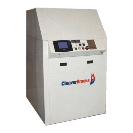
CleaverBrooks CFC Operation, Service & Parts Manual (457 pages)
Condensing Boiler
Brand:
CleaverBrooks
| Category:
Boiler
| Size: 14 MB
Table of Contents
Warnings
2
Table of Contents
5
Section 1 - Introduction
8
CFC Features and Benefits
8
Standard Equipment
9
The Boiler
9
Burner Gas Train
9
Control
10
Component/Connection Locations
11
Optional Equipment
11
Product Cutaway View
12
Boiler Safety Valve & Air Vent View
13
Return Temperature Sensor Mounting View
13
Outlet Temperature Sensor, Top of Pressure Vessel View
14
Stack Right Side View
14
Installation
15
Section 2 - Installation
16
Assembly
17
Packaging
17
Boiler Placement
17
Clearance Required
17
Casing Assembly
18
Standard Rigging Arrangement
18
Flue Gas/Combustion Air Connections
24
Water Treatment
25
Model CFC Water Chemistry
25
Model CFC Water Temperature Data (Non-Glycol)
26
Using Glycol
26
Glycol Application Guidelines
27
Boiler Room
28
Gas Connections
28
Gas Train Components
28
Direct Vent Combustion Air Diagram
28
General
28
Gas Pressure Requirements
29
Gas Piping
30
Test Cocks - Gas Valve Diagram
30
Gas Supply Pipe Sizing
31
Gas Line Capacity - Schedule 40 Metallic Pipe
32
Gas Header
34
Gas Piping Diagram
35
Boiler Water Piping
36
Safety Valve
36
Dual Return Design
36
General
36
Pressure Drop Curves
37
Maximum Flow Rate through Clearfire Boilers
40
Condensate Removal and Treatment
41
Condensate Tank Setup Options
42
Condensate Piping for Multiple Boilers
43
Condensate Treatment Tank for Multiple Boilers
44
Electrical Connections
45
Wiring Diagrams
48
Transformer Detail Diagrams
52
Stack and Intake Vent Sizing and Installation
53
Venting Connections - General
54
Appliance Categories
54
Vent Stack
54
Section 3 - Stack and Intake Vent Sizing and Installation
54
Vent Terminal Location
55
Vent Termination Requirements
56
A Vent Shall Not Terminate
56
Horizontal Thru-Wall Venting / Inside Combustion Air
57
Venting Installation Tips
57
Horizontal Thru-Wall Venting / Direct Vent Combustion Air
58
Horizontal Thru-Wall Stack Vent Termination
58
Installation
58
Horizontal Thru-Wall Stack Vent Termination
59
Vertical Venting / Inside Combustion Air
60
Vertical Stack with Inside Combustion Air Diagram
60
Vertical Venting / Direct Vent Combustion Air
61
Vertical Stack with Direct Vent Combustion Air Diagram
61
Stack Sizing
62
Stack Design Using Room Air for Combustion
62
Stack Design Using Direct Vent Combustion
63
Venting for Multiple Units
64
Combustion Air / Boiler Room Ventilation Requirements
66
Air Supply - Unconfined Spaces
66
All Air from Outdoors
67
Two Opening Outside Wall Method
67
Two Opening Ducted Method
68
Air Supply - Engineered Method
69
One Opening Method
69
Two Opening Engineered Method
70
Direct Vent Combustion
71
Optional Direct Vent Combustion Kit
71
CFC Commissioning
73
Operating Conditions
74
Filling Boiler
74
Control Setpoints
74
Section 4 - Commissioning
74
CFC Commissioning
74
Model CFC Boiler / Burner Controller
75
CB Falcon Display/Operator Interface
76
Home Page
76
Status Page
76
Operation Page
77
Lockouts, Holds, and Alerts
77
Falcon Display/Interface Page Flow
77
Controller Configuration
78
Alarm Banner
78
CFC Falcon Parameters
79
Changing Parameter Settings
87
Safety Parameters
87
Program Module
88
Burner Sequence
88
Confirming Safety Parameter Changes
88
Fan Speed Settings
89
Initial Start-Up Procedure
90
Gas Train and Piping
90
Premix Burner Technology - Full Modulation
90
Power-Up
91
Operation Check: Gas Valve, Gas Pressure Switches, Ignition Fail
91
Low Gas Pressure Applications
91
LGPS - Low Gas Pressure Switch
92
CAPS - Combustion Air Proving Switch
92
HGPS and Gas Valve
92
Pilot Tests
93
Low Water Cutoff Check
93
Ignition Failture Check
93
Low and High Fire Adjustments
94
CFC 3300 & Low Gas Pressure Option
94
Main Gas Choke - High Fire Adjustment
94
Modulation off Point
95
Setting Combustion
95
High Air Pressure Switch Settings
96
To Set Combustion
96
Limit Controls Check
97
Post Start-Up Checkout Procedure
97
Procedures for LP (Propane) Gas
98
Single Fuel Units
98
Units with Optional Dual-Fuel Gas Train
99
Gas Selector Valve View
100
Falcon Control Functions and Customer Interface
101
Remote Enable and Remote 4-20Ma Input
102
Rate Limiting/Override
103
Configurable Pump/Aux Relay Contacts
103
Annunciator
104
Lead/Lag Control
104
Modbus Communication
105
Service and Maintenance
107
Cleaning Procedure / Disassembly
108
Section 5 - Service and Maintenance
108
Reassembly
109
Ignition and Flame Detection Systems
109
Electrode Spacing Diagram
109
When Replacing the Adjustable Flame Rod
110
Pilot and UV Scanner
111
Troubleshooting
112
Lockout Conditions
112
Light-Off Problems
112
Troubleshooting Chart
113
Parts
115
Recommended Spare Parts List
115
Boiler Mechanical Assembly Diagram
116
Section 6 - Parts
116
Boiler Mechanical Assembly Parts List
117
Boiler Mechanical Assembly CFC 3300 Diagram
118
Boiler Mechanical Assembly CFC 3300 Parts List
119
Vessel Diagram and Parts List
120
Casing Diagram and Parts List
121
Burner Door Assembly View and Parts List
122
Burner Door Assembly CFC 3300 View and Parts List
123
Gas Train - Single Fuel 500-2500 View and Parts List
124
Gas Train, Dual Fuel: CFC 1000 - 2500 View and Parts List
125
Gas Train, Dual Fuel: CFC 500 - 750 View and Parts List
126
Gas Train, Single Fuel - CFC 3300 View and Parts List
127
Gas Train, Dual Fuel - CFC 3300 View and Parts List
128
Electrical Assemblies View - Single Fuel 500-2500
129
Electrical Assemblies Parts List - Single Fuel 500-2500
130
Item 1 Control Panel
130
Item 10 Blower Fuse
130
Item 14 Circuit Breaker
130
Cables and Cable Harness View - Single Fuel 500-2500
131
Electrical Assemblies View and Parts List - Dual Fuel 500-2500
132
Cables and Cable Harness View and Parts List - Dual Fuel 500-2500
133
Electrical Assemblies - CFC 3300
134
Cables and Cable Harness - CFC 3300
135
Optional Parts
136
Air Filter
136
Direct Vent Kits
136
Misc. Optional Parts
137
Vent (Flue) Connections
137
Appendix A - CB Falcon Hydronic Control
139
Application
141
Boiler Control System Installation and Operation
141
CB Falcon System May Consist of
141
Models Available
142
Features
144
Inputs/Outputs
144
Integrated Control Functions
144
Safety and Boiler Protection
144
Operational Features
145
Required Components
146
Temperature Settings
146
Connector Kit
147
Communications and Displays
148
Overview
148
Falcon Dimensions
149
Specifications
149
Device Power Supply, 24Vac
150
Ground Connection
150
Wiring
150
Installation
150
When Installing this Product
150
Final Wiring Check
151
High Voltage Cable
151
Limit String and Annunciator Inputs and Safety Load Outputs
151
UV Flame Detection
151
Falcon Device Pin out (Hydronic)
153
Falcon Device Pin out (Steam)
154
Falcon Contact Table
155
Valve Load Ratings
157
Commissioning
158
Parameter Control Blocks (PCB)
158
Passwords
158
Startup
158
Functional Sub Systems
159
Programming Safety Parameters
159
System Operation Settings
159
Demand and Rate
162
Demand/Rate Selection and Limiting
162
PID Requirements as a Replacement for MCBA Control
162
Demand and Rate Selection Diagram
163
DHW Priority Timer Logic
163
Burner Demand Priority Control
164
CH Hydronic Loop Demand and Rate
164
Central Heating Hydronic Diagram
165
Central Heating Hydronic Parameters
165
Outdoor Reset and Boost
166
Outdoor Reset and Boost Parameters
167
Outdoor Reset with TOD and Boost
167
Outdoor Reset Parameters
168
Steam Loop Demand and Rate
168
Central Heating Steam Diagram
169
Central Heating Steam Parameters
169
Setpoint and Hysteresis (Hydronic)
170
Setpoint and Hysteresis (Steam Control)
171
DHW Loop Demand and Rate (Hydronic Only)
173
Domestic Hot Water Function
173
Plate Heat Exchanger
175
Tap Demand
175
Plate Heat Exchanger Parameters
176
Plate Heat Exchanger Subsystem
176
Preheat Demand
177
DHW Storage
178
Preheat Modulation Control
178
Tap During Preheat
178
DHW Storage Demand Parameters
179
DHW Storage Operation
180
Frost Protection (Hydronic Only)
180
CH Frost Protection Parameters
181
DHW Frost Protection
181
Delta-T Limit (Rate Limit Only/Hydronic Only)
183
Rate Limit Priorities
183
Rate Limits and Override
183
T-Rise Parameters
184
Heat Exchanger High Limit
185
Outlet High Limit (Safety Limit and Rate Limit/Hydronic Only)
186
Stack Limit (Safety Limit and Rate Limit)
186
Stepped Modulation Rate Limit
186
Slow Start and Forced Rate Limits (Hydronic Control)
188
DHW High Limit (Hydronic Control)
189
Limits and Rate Override: Outlet High Limit
189
Anticondensation (Hydronic Control)
190
Common Modulation Parameters
190
Modulation Output
190
Fan Speed Modulation Parameters
191
Analog Modulation Parameters
192
Pump Control
193
Pump Control Block Parameters
193
Firing for Local Frost Protection
195
Frost Protection Requests
195
Pump Exercising
195
Pump X, Y, and Z
195
Burner Control Safety Parameters (Established by the OEM)
196
The Burner Control Uses
196
Interrupted Pilot Diagram
198
Direct Burner Ignition Diagram
199
Intermittent Pilot Diagram
199
Annunciator Section
201
Checkout
201
Annunciator Display
202
Example of Annunciator Inputs and Terminal Names
202
Sorting
202
Alarms for Alerts
203
Fault Handling
203
Lockouts and Alerts
203
Burner Control Operation
204
Operational Sequence
204
Safety Shutdown of Burner Control Functions
204
Central Heating
205
Domestic Hot Water
205
System Checkout
205
Checkout Summary
206
Initial Lightoff Checks
206
Preliminary Inspection
206
Proved Pilot Systems
206
Direct Burner Ignition (DBI) Systems
207
Pilot Turndown Test - All Installations Using a Pilot
208
Hot Refractory Hold-In Test - Ultraviolet Detectors
209
Ignition Interference Test - Flame Rods
209
Ignition Spark Response Test - Ultraviolet Detectors
209
Flame Signal with Hot Combustion Chamber
210
Response to Other Ultraviolet Sources
210
Safety Shutdown Tests - All Installations
210
Diagnostic Information Index
211
Historical Information Index
211
Troubleshooting
211
Lead Lag
212
System Diagnostics
211
Assumptions
212
Add-Stage Method, Add-Stage Detection Timing, Add-Stage Request
213
Drop-Stage Method, Drop-Stage Detection Timing, Drop-Stage Request
213
Lead Lag Wiring Diagram
213
Basic Operation
214
Lead-Lag Operation
214
Local Display Configuration and Operation
214
System Component Failure Responses
214
OEM Configuration Parameters
215
Slave Data Supporting Lead Lag
215
Slave Operation and Setup
215
System Display Configuration
215
Master/Slave Data Transmission
216
Slave Data Supporting Lead Lag Parameters
216
LL Master Operation and Setup
217
Overall Control Parameters
217
Periodic Data Polling Messages
218
Slave Control Messages
218
Slavestate States
218
Demand and Priority
219
Frost Protection
220
Modulation
221
Modulation Sensor Parameters
221
On/Off Hysteresis Parameters
222
Setpoint Parameters
222
Integrator Compensation
223
Lead Lag Burner Demand
223
Rate Adjustments
223
Rate Allocation
223
Rate Allocation Method - Parallel Common-Base Limited
224
Rate Allocation Parameters
224
Stager
224
Add-Stage Methods
225
Adding Stages Parameters
225
Dropping Stages
225
Drop-Stage Methods
226
Sequencer Add Boiler Selection
226
Sequencer Parameters
226
Forced Lead Rotation
227
Sequencer Ordering Function
227
Voluntary Lead Rotation
227
Sequencer 1 Minute Event
228
Sequencer Drop Lag Boiler Selection
228
Appendix A: Parameter Glossary
229
Example of a Completed Device Parameter Worksheet
240
Appendix B: Hydronic Device Parameter Worksheet Example
240
Appendix C: Lockout and Hold Codes
245
Alerts
253
Appendix B - CB Falcon Display/Operator Interface
261
System Display Features and Specifications
263
Replacement Parts
263
Display Safety Features
264
Display Installation Instructions
264
Display Dimensions
264
Display Wiring
265
8-Pin Connector Terminals
265
Wiring Diagram for Lead Lag
266
Building Automation System (BAS) Configuration
267
Starting the S7999D OI Display
267
Power-Up Validation
267
Display Quick Setup
267
Page Navigation
268
Common OI Display Page Symbols
268
833-5105 Display Page Flow
268
Configure Button
269
Configuration Password
269
Keyboard
270
Change Parameter Settings
270
Verify
271
Fault/Alarm Handling
272
History Button
272
Operation Button
274
Diagnostics Button
274
System Configuration
274
R7910A Hydronic Control, R7911 Steam Control Configuration Parameters
275
System Synchronization
275
Functional Configuration Groups
275
Central Heat Parameters (Hydronic Control Only)
276
System Identification Information
276
Outdoor Reset Parameters (Hydronic Control Only)
277
Domestic Hot Water (DHW) Configuration Parameters
277
Steam Configuration Parameters
277
Outdoor Reset Configuration Parameters
277
DHW Storage Configuration
278
DHW Plate Heat Exchanger Configuration
278
Warm Weather Shutdown Configuration
279
Demand Priority Configuration Parameters
279
Modulation Configuration Parameters
280
Steam Modulation Configuration Parameters
280
Pump Configuration Parameters
281
Statistics Configuration Parameters
282
High Limit Configuration Parameters (Hydronic Control Only)
282
Stack Limit Configuration Parameters
283
Delta T Limit Configuration Parameters
283
T-Rise Limit Configuration Parameters
284
Anti-Condensation Configuration Parameters
284
Heat Exchanger High Limit Configuration Parameters
284
Frost Protection Parameters
285
Annunciation Configuration Parameters
285
Safety Parameter Verification
287
Individual Configuration Parameters
289
Fan Parameters
289
Lead Lag Slave Configuration Parameters (Hydronic Control Only)
290
Lead Lag Master Configuration Parameters (Hydronic Control Only)
290
Details
292
Status
292
Burner Control Status
294
Hydronic Demand and Modulation Status
294
Inlet Temperature Status
295
Fan Status
295
Hydronic Pump Status
295
Flame Detection Status
296
Statistics Status
296
Stack Limit Status
296
Lead Lag Slave Status - Hydronic Only
296
Diagnostics
297
Lead Lag Master Status - Hydronic Only
297
Installer Chechout
298
Display Setup and Diagnostics
298
Diagnostics Tests
298
Trend Analysis Page
300
Trend Analysis Snapshot
302
Date and Time
302
Version
303
Display Reset
303
Configurable Parameters
304
8 33-5105 Front-Mount Cutout Template
312
833-5105 Rear-Mount Cutout Template
313
Appendix C - CB Falcon Plug-In Module
315
Program Module Specifications and Features
317
Program Module Operation
318
Button Actions
318
Backup Data
319
Appendix D - Gas Valve
321
Application
323
Gas/Air Servo Regulated Gas Valves Features
323
Gas/Air Servo Regulated Gas Valves Specifications
324
Gas/Air Servo Regulated Gas Valves - Ordering Information
325
V4730C/V8730C Gas Valves Diagrams
326
V4734C Gas Valve Diagrams
327
Venturi 150-335 Kw Gas Valves and Valve Shutoff Kit Diagrams
328
Venturi 500Kw, with V4730 Gas Valve Diagrams
329
V4734 + VMU 500/680 Diagram
331
Capacity Curves for V4730C/V8730C and VMU 150 Venturi, 1/2 In. Size
332
Capacity Curves for V4730C/V8730C and VMU 300 Venturi, 3/4 In. Size
332
Capacity Curves for V4730C/V8730C and VMU 300 Venturi, 1 In. Size
333
Capacity Curves for V4730C/V8730C and VMU 335 Venturi, 1-1/4 In. Size
333
Capacity Curves for V4730C/V8730C and VMU 500 Venturi, 1-1/4 In. Size
334
Capacity Curves for V4734C/V8734C and VMU 680 Venturi, 1-1/4 In. Size
334
Main Gas Connection
335
Mounting Locations
335
Mounting Position
335
Valves Installation
335
Adjustments and Final Checkout
336
Electrical Connections
336
Pressure Tap Points
336
Second Valve, Fast Opening
336
Gas/Air Servo Regulated Gas Valves Operation
337
Valve Leak Test
337
Gas/Air Servo Regulated Gas Valves Troubleshooting
338
Screen/Strainer Replacement
338
Service Information
338
Valves Scheduled Inspection and Maintenance
338
DUNGS Gas Valve (CFC 3300) View
340
Lead Seal
341
Setting the Pressure Controller
341
Space Requirements for Fitting Filter
342
Appendix E - CB Falcon Lead Lag Operation
343
CB Falcon Lead/Lag Installation and Startup
345
CFC Efficiencies
346
Hydronic Systems
346
Steam Systems
346
System Requirements
346
CB Falcon Lead/Lag Features
347
Falcon Lead/Lag Specifications
347
CB Falcon Lead/Lag Parts and Controls
348
Lead Lag Kits
349
Falcon Lead/Lag System Setup
350
Four Boiler Lead Lag System Diagram
350
Lead Lag Modbus Network
350
Falcon Communication Wiring
351
Header Temp. Sensor (Hydronic)
351
Header Temperature Sensor (Hot Water Systems)
351
Header Pressure Transmitter (Steam Systems)
352
Outdoor Temperature Sensor (Optional; Hot Water Only)
352
Connecting to a Building Energy Management System (EMS)
353
Falcon Lead/Lag System Commissioning
353
Lead Lag Master Configuration
353
Lead Lag Master Configuration Parameters
354
Lead Lag Master Configuration Parameters - Advanced Settings, Hydronic
355
Lead Lag Master Configuration Parameters - Advanced Settings, Steam
356
Lead Lag Slave Configuration
357
Copying Parameters to Remaining Slaves
358
Lead Lag Slave Configuration Parameters
358
Enable Master
360
Outdoor Reset Configuration (Hot Water Only)
360
Monitoring the Lead Lag System Performance
361
To Start the Lead Lag System
361
Example Systems
362
Lead Lag Home Page
362
Falcon Lead Lag with Outdoor Reset and EMS for Remote Comms/Monitoring
363
Falcon Lead Lag with Outdoor Reset and EMS for Remote Enable
364
Falcon LL with EMS for Remote Enable/Remote Setpoint
365
Falcon Lead Lag with EMS for Remote Comms/Monitoring
366
Typical Steam System
367
Isolation Valve Control
368
Primary Pumping
368
System Pump Enable
368
Primary/Secondary Piping
369
Primary with Dedicated System/Boiler Pumps
370
Domestic Hot Water Priority on Slave
371
Pump Control Block (PCB) Examples
372
System Pump Charts
372
Boiler Pump Charts
373
DHW Pump Charts
374
Central Heat Pump Charts
375
Aux 1 Pump Charts
376
Aux 2 Pump Charts
377
Combustion Air Damper
377
Boiler Wiring Diagrams
378
Model CFC Clearfire Condensing Boiler Wiring Diagram
378
Model CFW Clearfire Hydronic Boiler Wiring Diagram
379
Model CFV/CFH Clearfire Steam Boiler Wiring Diagram
380
General Description of the Lead Lag Application
381
Lead Lag (LL) Master General Operation
381
Lead Lag Operation
381
Reference Manual
381
System Wiring Hookup
383
Lead-Lag Operation Description
384
Slave Operation and Setup
385
Aux Pump X, Y, and Z
386
Slave Parameters
386
LL Master Operation and Setup
387
Overall Control
387
Data Poll Response Handling
388
Features Common to All States
388
Slave Control
388
Slave Status Manager
388
CH Demand
389
Warm Weather Shutdown
389
Master Status
390
Outdoor Temperature
390
Priority Control
390
Modulation Sensor
391
Setpoints
391
Lead Lag PID
392
Rate Adjustment
392
Common Features
393
Rate Allocation Methods
394
Burner Demand
395
Drop-Stage Interstage Delay
395
Functions Common to All Stager States
395
Stager Parameters
395
Add Stage Methods
396
Stager States
396
Drop Stage Methods
397
Error Threshold
397
Rate Threshold
397
Boiler off Options
398
Sequencer
398
MODBUS Building Energy Management System (EMS) Interface
401
Enabling Modbus Communications
402
Modbus Interface - Physical Layer
402
Application Layer
403
RS-485 Message Format
403
Modbus Registers
404
Appendix F - CB Falcon Modbus Communication
413
Sensor Input Names
414
Register Map
415
CB Falcon Modbus Register Map
416
CB Falcon Lockout History Record
443
Annunciator Configuration
443
PII, LCI, ILK Terminal Configuration
443
Falcon Lockout and Hold Codes
444
Falcon Alert Codes
447
Burner Control States
453
Pump Status Codes
454
Register Writes
455
03 (0X03) Read Holding Registers
455
06 (0X06) Write Single Register
455
16 (0X10) Write Multiple Registers
456
Exception Codes
456
17 (0X11) Report Slave ID
456
Advertisement
CleaverBrooks CFC Operation, Service And Parts Manual (270 pages)
Gas High Efficiency Boiler
Brand:
CleaverBrooks
| Category:
Boiler
| Size: 7 MB
Table of Contents
Table of Contents
5
CFC Features and Benefits
8
Burner Gas Train
9
Chapter 1
9
Standard Equipment
9
The Boiler
9
The Burner
9
Component/Connection Locations
10
Control
10
Optional Equipment
11
Section 2 Installation
15
Section 2 - Installation
16
Assembly
17
Packaging
17
Boiler Room
17
Mounting Legs
18
Insulation
18
Casing Assembly
20
Base Mounting
22
Boiler Room
23
Flue Gas / Combustion Air Connections
23
Flue Gas/Combustion Air Connections
23
Water Treatment
23
Gas Connections
24
General
24
Gas Train Components
24
Gas Pressure Requirements
24
Gas Piping
25
Gas Supply Pipe Sizing
26
Gas Header
32
Boiler Water Piping
34
General
34
Water Temperature Sensors
34
Safety Valve
34
Pressure Drop Curves
34
Condensate Removal and Treatment
41
Condensate Tank Installation
41
Condensate Tank Setup Options
42
Condensate Take-Off and Neutralization
42
Condensate Discharge into Local Drain
42
Piping Treated Condensate to Drain
42
Installation
43
Condensate Piping for Multiple Boilers
44
Electrical Connections
45
Wiring Diagrams
47
Chapter 3 Stack and Intake Vent Sizing and Installation
49
Appliance Categories
50
Stack and Intake Vent Sizing and Installation
50
Vent Stack
50
Venting Connections - General
50
Vent Terminal Location
51
Horizontal Thru-Wall Venting / Inside Combustion Air
54
Installation
54
Horizontal Thru-Wall Stack Vent Termination
54
Horizontal Thru-Wall Venting / Direct Vent Combustion Air
55
Installation
55
Horizontal Thru-Wall Stack Vent Termination
56
Vertical Venting / Inside Combustion Air
57
Vertical Venting / Direct Vent Combustion Air
58
Chapter 4 Cfc Commissioning
63
Control Setpoints
64
Filling Boiler
64
Model CFC Boiler / Burner Controller
64
Operating Conditions
64
CB Falcon Display/Operator Interface
65
Home Page
65
Status Page
65
Operation Page
66
Controller Configuration
67
Lockouts and Alerts
67
Changing Parameter Settings
73
Burner Sequence
74
Fan Speed Settings
75
Initial Start-Up Procedure
75
Gas Train and Piping
75
Power-Up
76
LOW WATER CUTOFF Check
78
Low and High Fire Adjustments
78
Modulation off Point
79
Setting Combustion
79
High Air Pressure Switch Settings
81
Limit Controls Check
81
Post Start-Up Checkout Procedure
82
Chapter 5 Service and Maintenance
83
Service and Maintenance
83
Cleaning Procedure / Disassembly
84
Assembly
85
Condensate Neutralization
85
Ignition Electrode and Flame Rod
86
Troubleshooting
86
Chapter 6 Parts
89
Boiler Mechanical Assembly
90
Boiler Mechanical Assembly Parts List
91
Connection Sizes
91
Gas Train
92
Gas Train Parts List
92
MSOV Kit
92
Electrical Assemblies
93
Blower Fuse
94
Control Panel
94
Electrical Assemblies Parts List
94
Appendix A - CB Falcon Hydronic Control
97
Table of Contents
101
Communications and Displays
105
Overview
105
Installation
107
Wiring
107
Parameter Control Blocks (PCB)
114
Startup
114
Programming Safety Parameters
115
Burner Control
133
Boiler Pump
143
Annunciator
146
Fault Handling
149
Lockouts and Alerts
149
Alarms for Alerts
149
Sensor Signal Conditioning
149
Burner Control Operation
150
Safety Shutdown of Burner Control Functions
150
Operational Sequence
150
Parameter Glossary
152
Global Modbus
161
Appendix B - Falcon Display/Operator Interface
197
833-3577 Cb-Falcon System Operator Interface
199
Preface
200
Safety Features
201
Installation Instructions
201
Wiring
201
Quick Setup
202
Starting the Display
202
Page Navigation
203
Configuration Password
205
Configuration
213
Monitoring
226
833-3639 Diagnostics
238
Display Setup and Diagnostics
240
Advanced Setup
246
System Time
248
Appendix C - Gas Valve
251
Application
253
Specifications
254
Ordering Information
255
Installation
265
Electrical Connections
266
Adjustments and Final Checkout
266
Operation
267
Troubleshooting
268
Service Information
268
Advertisement
Related Products
CleaverBrooks CFC ClearFire
CleaverBrooks CFC-500
CleaverBrooks CFC-750
CleaverBrooks CFC-2500
CleaverBrooks CFC-1000
CleaverBrooks CFC-1500
CleaverBrooks CFC-1800
CleaverBrooks ClearFire CFC 3300
CleaverBrooks CFC-E Series
CleaverBrooks CFC-E 500
CleaverBrooks Categories
Boiler
Burner
Boiler Supplies
Control Unit
Control Panel
More CleaverBrooks Manuals
Login
Sign In
OR
Sign in with Facebook
Sign in with Google
Upload manual
Upload from disk
Upload from URL