Sign In
Upload
Manuals
Brands
CleaverBrooks Manuals
Boiler
CFC-750
CleaverBrooks CFC-750 Manuals
Manuals and User Guides for CleaverBrooks CFC-750. We have
2
CleaverBrooks CFC-750 manuals available for free PDF download: Operation, Service And Parts Manual, User Manual
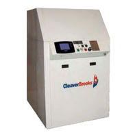
CleaverBrooks CFC-750 Operation, Service And Parts Manual (314 pages)
ClearFire Condensing Boiler
Brand:
CleaverBrooks
| Category:
Boiler
| Size: 7 MB
Table of Contents
Section 1 - Introduction
5
Table of Contents
5
Section 1 - Introduction
8
CFC Features and Benefits
8
Standard Equipment
9
The Boiler
9
The Burner
9
Burner Gas Train
9
Control
10
Component/Connection Locations
11
Optional Equipment
11
Section 2 Installation
15
Section 2 - Installation
16
Assembly
17
Packaging
17
Boiler Placement
17
Casing Assembly
18
Flue Gas/Combustion Air Connections
24
Water Treatment
25
Using Glycol
26
Boiler Room
28
Gas Connections
29
General
29
Gas Train Components
29
Gas Pressure Requirements
29
Gas Piping
30
Gas Supply Pipe Sizing
31
Gas Header
34
Boiler Water Piping
36
General
36
Safety Valve
36
Pressure Drop Curves
36
Condensate Removal and Treatment
43
Condensate Tank Setup Options
44
Condensate Piping for Multiple Boilers
45
Electrical Connections
46
Wiring Diagrams
48
Section 3 Stack and Intake Vent Sizing and Installation
51
Section 3 - Stack and Intake Vent Sizing and Installation
52
Venting Connections - General
52
Appliance Categories
52
Vent Stack
52
Vent Terminal Location
53
Horizontal Thru-Wall Venting / Inside Combustion Air
55
Installation
55
Horizontal Thru-Wall Stack Vent Termination
56
Horizontal Thru-Wall Venting / Direct Vent Combustion Air
56
Installation
57
Horizontal Thru-Wall Stack Vent Termination
57
Vertical Venting / Inside Combustion Air
58
Vertical Venting / Direct Vent Combustion Air
59
Stack Design Using Room Air for Combustion
60
Stack Sizing
60
Stack Design Using Direct Vent Combustion
61
Venting for Multiple Units
62
Combustion Air / Boiler Room Ventilation Requirements
64
Air Supply - Unconfined Spaces
64
Air Supply - Engineered Method
67
Section 4 Cfc Commissioning
71
Section 4 - Commissioning
72
Control Setpoints
72
CFC Commissioning
72
Filling Boiler
72
Operating Conditions
72
Model CFC Boiler / Burner Controller
73
CB Falcon Display/Operator Interface
74
Home Page
74
Status Page
74
Operation Page
75
Lockouts and Alerts
75
Controller Configuration
76
Changing Parameter Settings
85
Program Module
86
Burner Sequence
86
Fan Speed Settings
87
Initial Start-Up Procedure
88
Gas Train and Piping
88
Power-Up
89
Low Water Cutoff Check
91
Low and High Fire Adjustments
91
Modulation off Point
91
Setting Combustion
92
High Air Pressure Switch Settings
93
Limit Controls Check
93
Post Start-Up Checkout Procedure
94
Procedures for LP (Propane) Gas
95
Single Fuel Units
95
Units with Optional Dual-Fuel Gas Train
96
Falcon Control Functions and Customer Interface
98
Service and Maintenance
103
Cleaning Procedure / Disassembly
104
Section 5 - Service and Maintenance
104
Ignition Electrode and Flame Rod
105
Reassembly
105
Troubleshooting
105
Section 6 - Parts
110
Table of Contents
127
Features
128
Operational Features
129
Lockout History
129
Temperature Settings
130
Communications and Displays
132
Specifications
133
Installation
134
Wiring
134
Appendix A - CB Falcon Hydronic Control
137
Startup
142
Pump Control
177
Annunciator
185
Fault Handling
187
Burner Control Operation
188
System Checkout
189
Central Heating
189
Initial Lightoff Checks
190
Pilot Turndown Test
192
Hot Refractory Hold-In Test
193
Ignition Interference Test
193
Ignition Spark Response Test
193
Safety Shutdown Tests
194
Troubleshooting
195
Lead Lag
196
Modulation Sensor
205
Rate Allocation
207
Appendix A: Parameter Glossary
224
Appendix A: Parameter Glossary
224
Appendix B: Hydronic Device Parameter Worksheet Example
224
Appendix C: Lockout and Hold Codes
229
Appendix B - CB Falcon Plug-In Module
245
Appendix C - Gas Valve
251
V4730C/V8730C/V4734C
253
Application
253
Specifications
254
Ordering Information
255
Installation
265
Adjustments and Final Checkout
266
Electrical Connections
266
Operation
267
Service Information
268
Appendix D - CB Falcon Modbus Communication
271
Troubleshooting
268
Advertisement
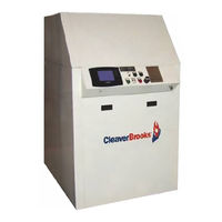
CleaverBrooks CFC-750 User Manual (70 pages)
CFC Series Condensing Boiler
Brand:
CleaverBrooks
| Category:
Boiler
| Size: 1 MB
Table of Contents
Table of Contents
2
Model Cfc Features and Benefits
3
Premix Burner Technology
4
Model Cfc Product Offering
5
Clearfire Control Panel
7
Dimensions and Ratings
8
Model CFC Dimensional Views
9
U.S. Standard Dimensions Model CFC Boiler
10
Metric Dimensions Model CFC Boiler
11
Model CFC Boiler Ratings (Sea Level to 2000 Feet)
12
Altitude Correction for Input Capacity at Various Altitude Levels
13
Competitive Condensation Analysis
14
Clearfire Efficiency
15
Emissions Data Clearfire
16
Emissions Data Clearfire
19
Engineering Data
20
CFC Flow Rates
21
Pressure Drop Curves
22
Pressure Drop Curves
25
Model CFC Minimum over Pressure Requirements
26
Model CFC Water Chemistry Requirements in Accordance with ABMA
27
Glycol Application Guidelnes - Model CFC
28
Max Firing Rate Vs. Glycol Concentration
29
Condensate Piping Direct to Drain
30
Optional Condensate Treatment Assembly
31
Condensate Treatment Tank for Multiple Boilers
32
Gas Piping Schematic
33
Gas Header Piping
34
Model CFC Minimum and Maximum Gas Pressure
35
Model CFC Minimum Room Clearance Dimensions
36
No Primary Loop with Domestic Water and 2-Way Divert Valve
38
Two Boilers and Three Variable Temperature Zones (no Primary Loop)
39
Two-Pipe Primary/Secondary Piping with Domestic Hot Water
40
Two-Pipe Primary/Secondary Piping
41
No Primary Loop
42
Domestic Water Heating, no Primary Loop
43
Domestic Water with On/Off and 3-Way Valves
44
Piping 'Hybrid' Boilers
45
Hybrid' Boilers with Domestic Water
46
Pipe System, Typical (Reverse-Return)
47
Zoning with Zone Valves
48
Domestic Water with 2 Boilers and 2 Coils
49
Two Opening Outside Wall Method
51
Two Opening Ducted Method
52
One Opening Method
53
Two Opening Engineered Method
54
Stack/Breeching Size Criteria
55
Horizontal through the Wall Venting Using Inside Air for Combustion
58
Horizontal Flue Through-Wall with Direct Vent Combustion Intake
59
Stack Design (Single Boiler) Using Room Air
60
Stack Sizing Using Outside Air for Combustion (Direct Vent Combustion)
61
Inside Air - Vertical Vent
62
Vertical Stack with Direct Vent Combustion Air
63
Electrical Connections CFC 500-2500
64
Electrical Connections CFC 3300
65
CFC Rear Connections
66
Cb Falcon Controller
67
CB Falcon Burner Sequence (Central Heat)
68
CB Falcon Pinout
69
Advertisement
Related Products
CleaverBrooks CFC ClearFire
CleaverBrooks CFC
CleaverBrooks CFC-500
CleaverBrooks CFC-2500
CleaverBrooks CFC-1000
CleaverBrooks CFC-1500
CleaverBrooks CFC-1800
CleaverBrooks ClearFire CFC 3300
CleaverBrooks CFC-E Series
CleaverBrooks CFC-E 500
CleaverBrooks Categories
Boiler
Burner
Control Unit
Control Panel
Boiler Supplies
More CleaverBrooks Manuals
Login
Sign In
OR
Sign in with Facebook
Sign in with Google
Upload manual
Upload from disk
Upload from URL