Sign In
Upload
Manuals
Brands
Chrysler Manuals
Automobile
2004 Pacifica
Chrysler 2004 Pacifica Manuals
Manuals and User Guides for Chrysler 2004 Pacifica. We have
3
Chrysler 2004 Pacifica manuals available for free PDF download: Service Manual, Manual
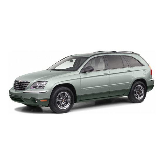
Chrysler 2004 Pacifica Service Manual (3603 pages)
Brand:
Chrysler
| Category:
Automobile
| Size: 72.42 MB
Table of Contents
Table of Contents
4
General Information
10
System Coverage
10
Six-Step Troubleshooting Procedure
10
Identification of System
10
Introduction
10
System Description and Functional Operation
11
Fuel Control
11
On-Board Diagnostics
11
MIL Lamp Strategy
11
Obd II Monitor Run Process
13
Monitor Preliminary Checks
13
Natural Vacuum Leak Detection with Purge Monitor
13
Catalyst / O2 Monitor
13
Other Controls
14
EGR Monitor
14
O2 Sensor Heater Monitor
14
Speed Control System
14
The Pcm’s Role in Nvld Diagnosis
15
Nvld Leak Detection
15
Small Leak Test (Passive)
15
Rationality Tests
15
Natural Vacuum Leak Detection System
16
NVLD Assembly Internal Schematic
17
Pcm Operating Modes
18
Non-Monitored Circuits
18
Sentry Key Remote Entry System (Skrees) Overview
18
Skreem On-Board Diagnostics
18
Skrees Operation
19
Programming the Powertrain Control Module
19
Programming the Skreem
20
Programming the Ignition Keys to the Skreem
20
Diagnostic Trouble Codes
20
Hard Code
20
Intermittent Code
21
Starts Since Set Counter
21
Distance Since MI Set
21
Drbiii Does Not Power up
21
Display Is Not Visible
22
Disclaimers
22
Safety
22
Servicing Sub Assemblies
22
Warnings and Cautions
23
Road Test Warnings
23
Vehicle Damage Cautions
23
Required Tools and Equipment
23
Diagnostic Information and Procedures
26
No Response from Pcm (Pci Bus)
27
No Response from Pcm (Pcm Sci Only)
28
No Response from Sentry Key Remote Entry Module
31
No Response from Transmission Control Module
33
Pci Bus Communication Failure
36
Intermittent Condition
39
P0016-Crankshaft/Camshaft Timing Misalignment
40
P0031-O2 Sensor 1/1 Heater Circuit Low
44
P0032-O2 Sensor 1/1 Heater Circuit High
46
P0038-O2 Sensor 1/2 Heater Circuit High
46
P0068-Manifold Pressure/Throttle Position Correlation
49
P0071-Ambient Temp Sensor Performance
55
P0072-Ambient Temp Sensor Low
58
P0073-Ambient Temp Sensor High
60
P0107-Map Sensor Low
62
P0108-Map Sensor High
65
P0111-Intake Air Temperature Sensor Performance
68
P0112-Intake Air Temperature Sensor Low
71
P0113-Intake Air Temperature Sensor High
73
P0116-Engine Coolant Temperature Performance
75
P0117-Engine Coolant Temperature Sensor Low
78
P0118-Engine Coolant Temperature Sensor High
80
P0122-Throttle Position Sensor #1 Low
82
P0123-Throttle Position Sensor #1 High
85
P0125-Insufficient Coolant Temp for Closed-Loop Fuel Control
88
P0128-Thermostat Rationality
90
P0129-Barometric Pressure Out-Of-Range Low
95
P0131-O2 Sensor 1/1 Voltage Low
98
P0132-O2 Sensor 1/1 Voltage High
101
P0133-O2 Sensor 1/1 Slow Response
104
P0135-O2 Sensor 1/1 Heater Performance
106
P0171-Fuel System 1/1 Lean
109
P0172-Fuel System 1/1 Rich
114
P0201-Fuel Injector #1
118
P0300-Multiple Cylinder Misfire
121
P0315-No Crank Sensor Learned
129
P0325-Knock Sensor #1 Circuit
131
P0335-Crankshaft Position Sensor Circuit
134
P0339-Crankshaft Position Sensor Intermittent
139
P0340-Camshaft Position Sensor Circuit
143
P0344-Camshaft Position Sensor Intermittent
148
P0401 - Egr System Performance
152
P0403 - Egr Control Circuit
155
P0404 - Egr Position Sensor Performance
158
P0405 - Egr Position Sensor Low
162
P0406 - Egr Position Sensor High
165
P0420-Catalytic 1/1 Efficiency
168
P0440-General Evap System Failure
170
P0441-Evap Purge System Performance
175
P0442-Evap System Medium Leak
177
P0443-Evap Purge Solenoid Circuit
182
P0452-Nvld Pressure Switch Sense Circuit Low
185
P0453-Nvld Pressure Switch Sense Circuit High
188
P0456-Evap System Small Leak
190
P0461-Fuel Level Sensor #1 Performance
192
P0462-Fuel Level Sensor #1 Low
195
P0480-Cooling Fan 1 Control Circuit
197
P0481-Cooling Fan 2 Control Circuit
199
P0498-Nvld Canister Vent Valve Solenoid Circuit Low
201
P0499-Nvld Canister Vent Valve Solenoid Circuit High
202
P0501-Vehicle Speed Sensor #1 Performance
204
P0506-Idle Speed Low Performance
205
P0507-Idle Speed High Performance
205
P0508-Iac Valve Sense Circuit Low
207
P0509-Iac Valve Sense Circuit High
210
P0513-Invalid Skim Key
212
P0516-Battery Temperature Sensor Low
214
P0517-Battery Temperature Sensor High
216
P0522 Pressure Sensor Low
218
P0532-A/C Pressure Sensor Low
219
P0533-A/C Pressure Sensor High
222
P0562-Battery Voltage Low
225
P0563-Battery Voltage High
228
P0572-Brake Switch #1 Circuit Low
230
P0573-Brake Switch #1 Circuit High
232
P0580-Speed Control Switch #1 Low
234
P0581-Speed Control Switch #1 High
236
P0582-Speed Control Vacuum Solenoid Circuit
238
P0586-Speed Control Vent Solenoid Circuit
240
P0594-Speed Control Servo Power Circuit
242
P0600-Serial Communication Link
245
P0622-Generator Field Control Circuit
246
P0627-Fuel Pump Relay Circuit
248
P0630-Vin Not Programmed in Pcm
250
P0632-Odometer Not Programmed in Pcm
251
P0633-Skim Key Not Programmed in Pcm
252
P0645-A/C Clutch Relay Circuit
253
P0660-Manifold Tune Valve Solenoid Circuit
255
P0685-Asd Relay Control Circuit
258
P0688-Asd Relay Sense Circuit Low
260
On the Drbiii
263
P0850-Park/Neutral Switch Performance
264
P1115-General Temp Sensor Performance
265
P1593-Speed Control Switch Stuck
269
P1602-Pcm Not Programmed
272
P1603-Pcm Internal Dual-Port Ram Communication
273
P1696-Eeprom Memory Write Denied/Invalid
274
P1861-Siphon Line Disconnected
276
P2008-Short Runner Solenoid Circuit
278
Flow/Vacuum Leak
280
P2096-Down Stream Fuel System 1/2 Lean
286
P2302-Ignition Coil #1 Secondary Circuit-Insufficient Ionization
289
P2503-Charging System Voltage Low
293
U0101-No Transmission Bus Message
296
U0140-No Body Bus Messages
298
U0155-No Cluster Bus Message
300
U0168-No Skim Bus Messages
301
U110C-No Fuel Level Bus Message
303
Checking Pcm Power and Ground Circuits
305
Checking the A/C Relay Output
306
Antenna Failure
308
Cop Failure
308
Eeprom Failure
308
Ram Failure
308
Pcm Status Failure
310
Serial Link External Fault
310
Rolling Code Failure
312
Vin Mismatch
312
Transponder Communication Failure
314
Unprogrammed Skreem
317
Checking Fuel Delivery
318
Checking Fuel Pressure Leak down
321
Checking Hard Start (Fuel Delivery System)
322
Engine Cranks Does Not Start
324
No Crank Condition
329
No Response from Pcm with a no Start Condition
332
Start and Stall Condition
333
Verification Tests
336
Component Locations
342
Control Modules
342
Control and Solenoids
342
Typical View
343
Sensor
344
Fuel System and Evap System
345
Switches
345
Connector Pinouts
346
Camshaft Position Sensor - Black 3 Way
347
Crankshaft Position Sensor - Black 3 Way
348
Data Link Connector - Black 16 Way
349
Egr Solenoid - Black 6 Way
349
Engine Coolant Temperature Sensor - Black 2 Way
349
Engine Oil Pressure Switch - Black 2 Way
349
Evap/Purge Solenoid - Black 2 Way
350
Fuel Injector No. 1 - Black 2 Way
350
Fuel Injector No. 2 - Black 2 Way
350
Fuel Injector No. 3 - Black 2 Way
351
Fuel Injector No. 4 - Black 2 Way
351
Fuel Injector No. 5 - Black 2 Way
351
Fuel Injector No. 6 - Black 2 Way
352
Fuel Pump Module - Black 6 Way
352
Generator - Black 2 Way
352
Intake Air Temperature Sensor - Black 2 Way
352
Fuses (Ipm)
354
Fuel Pump Relay
355
Integrated Power Module C1 - Black 15 Way
356
Integrated Power Module C2 - Dk. Gray 4 Way
356
Integrated Power Module C3 - Gray 2 Way
356
Integrated Power Module C4 - Green 16 Way
357
Integrated Power Module C5 - Gray 26 Way
357
Integrated Power Module C6 - Gray 12 Way
358
Integrated Power Module C7 - Gray 10 Way
358
Integrated Power Module C8 - White 15 Way
358
Integrated Power Module C9 - Blue 26 Way
359
Knock Sensor - Black 2 Way
359
Manifold Absolute Pressure Sensor - Gray 3 Way
359
Manifold Tuning Valve Solenoid - Dk. Gray 2 Way
360
Natural Vacuum Leak Detection Assembly - Black 3 Way
360
Oxygen Sensor-1/1 Upstream - Black 4 Way
360
Oxygen Sensor-1/2 Downstream - White 4 Way
360
Powertrain Control Module C1 - Black/Black 38 Way
361
Powertrain Control Module C2 - Black/Orange 38 Way
362
Powertrain Control Module C3 - Black/White 38 Way
363
Powertrain Control Module C4 - Black/Green 38 Way
364
Radiator Fan Motor No. 1 - Black 2 Way
364
Radiator Fan Motor No. 2 - Black 2 Way
365
Short Runner Valve Solenoid - Gray 2 Way
365
Skreem Module - Black 6 Way
365
Speed Control Servo - Black 4 Way
366
Speed Control Switch-Left - Black 3 Way
366
Speed Control Switch-Right - Black 3 Way
366
Throttle Position Sensor - Gray 3 Way
366
Schematic Diagrams
368
2004 Cs 3.5L
368
Cs 3.5L
369
Cs 3.5L
370
Charts and Graphs
372
NGC Typical Slope Patterns
372
Airbag System
399
Clockspring
402
Passenger Airbags
402
Seat Belt Tensioners
403
Curtain Airbags
403
Airbag Squib Status
403
Front Impact Sensors
404
Side Impact Sensors
404
Special Tools
404
Active Codes
405
Stored Codes
405
Audio System
405
Remote Radio Controls
406
CD/DVD Changer
406
Satellite Radio (Sdars)
406
Body Control Module (Bcm)
407
Chime Warning System
407
Chime Priority
408
Chime on Conditions
408
Driver’s Seat Belt Unbuckled
408
Exterior Lights on
408
Warning Lamp Announcement
409
Other Chime on Conditions
409
Low Fuel Lamp
409
Volt Lamp
409
Communication
410
Tire Pressure Monitor System
410
Door Ajar System
411
Door Modules
412
Power Door Locks
412
Power Windows
412
Door Lock Inhibit
413
Remote Keyless Entry
413
Panic Function
413
Rolling Code
413
Programmable Door Lock Features
414
Power Mirrors
414
Battery Protection Feature
414
Memory Master
414
Rear Window Defog/Heated Mirror
415
Exterior Lighting System
415
Headlamp Power
415
Front Fog Lamp
415
Heating & A/C System
416
Automatic Temperature Control (Atc)
416
System Availability
416
System Controls
416
System Revisions
417
System Diagnostics
417
Information Systems
419
Navigation
419
Instrument Panel Switch Pod
419
Electronic Vehicle Information Center (Evic)
419
Step Button
420
Menu Button
420
Traveler Display Functions
420
Compass Operation - All
420
Setting Magnetic Zone Variance
421
Compass Calibration
421
Homelink Universal Transmitter
422
Tire Pressure Monitoring System (Tpms)
422
Training the Cmtc
422
Pressure Thresholds
423
System Faults
423
Spare Wheel Auto-Detect
423
Diagnosing and Clearing System Faults
423
System Test
424
Training the Skreem
424
Active Fault and System Alerts
424
Compass/Mini-Trip Computer
424
Instrument Cluster
425
Instrument Cluster Self Test
425
Integrated Power Module
425
Controlled Power Feeds
425
Front Airbag System
426
Tail Lamps and Side Marker Lamps
426
Front Park Lamps
426
Front Washer Motor
426
Relay Controls
427
Front Wiper on Relay
427
Front Wiper High/Low Relay
427
Accessory Relay
427
Electrical Inputs
428
Interior Lighting
428
Courtesy Lamp Control
428
Illuminated Entry
428
Power Liftgate System
429
Power Liftgate
429
Power Seat Systems
429
Power Seat - Driver
429
Telecommunications
430
Power Seat - Passenger
430
Memory System
430
Hands Free Phone
430
Wiper System
431
Sentry Key Remote Keyless Entry (Skreem)
431
Front Wiper
431
Rear Wiper
431
Speed Sensitive Intermittent Wipe Mode
432
Wipe after Wash
432
Using the Drbiii
432
Drbiii Error Messages
432
Technician Safety Information
433
Vehicle Preparation for Testing
433
Servicing Sub-Assemblies
433
Warnings
434
Diagnostic Information and Procedures
436
Broken Cable - Mhsapm/Msapm
437
Broken Forward Cable - Mhsapm/Msapm
437
Broken Rearward Cable - Mhsapm/Msapm
437
Loss of Hall Forward Signal - Mhsapm/Msapm
437
Hall Feedback Signal Open - Mhsapm/Msapm
440
Pedal Hall Input Open - Mhsapm/Msapm
440
Pedal Hall Input Shorted Low - Mhsapm/Msapm
440
Pedal Forward Switch Stuck - Mhsapm/Msapm
443
Pedal Hall Input Shorted High - Mhsapm/Msapm
444
Pedal Rearward Switch Stuck - Mhsapm/Msapm
447
Pedal Sensor out of Range High - Mhsapm/Msapm
448
Pedal Sensor out of Range Low - Mhsapm/Msapm
451
Pedal Switch Stuck - DDM
454
Airbag Warning Indicator Driver
458
Airbag Warning Indicator Open
458
Airbag Warning Indicator Short
458
Calibration Mismatch
461
Cluster Message Mismatch
463
Driver Knee Blocker Circuit Open
465
Driver Knee Blocker Circuit Short
468
Driver Knee Blocker Short to Battery
471
Driver Knee Blocker Short to Ground
474
Driver Seat Belt Tensioner Circuit Open
477
Driver Seat Belt Tensioner Circuit Short
480
Driver Seat Belt Tensioner Short to Battery
483
Driver Seat Belt Tensioner Short to Ground
486
Driver Squib 1 Circuit Open
489
Driver Squib 1 Circuit Short
492
Driver Squib 1 Short to Battery
495
Driver Squib 1 Short to Ground
498
Driver Squib 2 Circuit Open
501
Driver Squib 2 Circuit Short
504
Driver Squib 2 Short to Battery
507
Driver Squib 2 Short to Ground
510
Left Curtain or Seat Squib Circuit Open
513
Left Curtain or Seat Squib Circuit Short
516
Left Curtain or Seat Squib Short to Battery
519
Left Curtain or Seat Squib Short to Ground
521
Left Front Impact Sensor Internal 1
524
Left Side Impact Sensor 1 Internal 1
526
Left Side Impact Sensor 2 Internal 1
528
Left Side Impact Sensor 3 Internal 1
530
No Cluster Message
540
No Left Front Impact Sensor Communication
542
No Left Side Impact Sensor 1 Communication
546
No Left Side Impact Sensor 2 Communication
550
No Left Side Impact Sensor 3 Communication
554
No Odometer Message
558
No Pci Transmission
561
No Right Front Impact Sensor Communication
563
No Right Side Impact Sensor 1 Communication
567
No Right Side Impact Sensor 2 Communication
571
No Right Side Impact Sensor 3 Communication
575
Passenger Seat Belt Tensioner Circuit Open
579
Passenger Seat Belt Tensioner Circuit Short
582
Passenger Seat Belt Tensioner Short to Battery
585
Passenger Seat Belt Tensioner Short to Ground
588
Passenger Squib 1 Circuit Open
591
Passenger Squib 1 Circuit Short
594
Passenger Squib 1 Short to Battery
597
Passenger Squib 1 Short to Ground
600
Passenger Squib 2 Circuit Open
603
Passenger Squib 2 Circuit Short
606
Passenger Squib 2 Short to Battery
609
Passenger Squib 2 Short to Ground
612
Power Supply Voltage Low
615
Right Curtain or Seat Squib Circuit Open
618
Right Curtain or Seat Squib Circuit Short
621
Right Curtain or Seat Squib Short to Ground
627
Right Front Impact Sensor Internal 1
630
Right Side Impact Sensor 1 Internal 1
632
Right Side Impact Sensor 2 Internal 1
634
Right Side Impact Sensor 3 Internal 1
636
Vehicle Body Style Mismatch
638
Airbag Indicator on Without Active Trouble Codes
641
All Outputs Short
642
Antenna Hardware Failure - Sdars
644
Antenna Not Connected - Sdars
645
Bus Busy - Sdars
647
Bus Low - Sdars
649
Cassette Player Inop
651
CD Changer Mechanical Failure
652
CD Changer Read Failure
653
CD Changer Temperature High
654
CD Play Failure
655
CD Read Failure
656
CD Temperature High
657
Eq Fault - no Eq Active - Amplifier
658
Internal Failure - Amplifier
659
Internal Failure - Sdars
660
Internal Receiver Failure - Sdars
661
Loss of Communication on Private Bus - Sdars
662
Low Voltage Level
665
Nav Messages Not Received - Amplifier
666
No Antenna Connection
667
No Communication with Amplifier - Radio
668
No Communication with Bcm - Radio
669
No Communication with CD/DVD Changer - Radio
670
No Communication with Nav - Radio
672
No Communication with Sdars - Radio
673
No J1850 Communication - Sdars
675
Pcm Messages Not Received - Amplifier
678
Power Amp Shutdown
679
Radio Messages Not Received - Amplifier
681
Remote Radio Switch Open
682
Remote Radio Switch Stuck
685
Software Checksum Failure - Amplifier
688
Amplifier Pretest
689
Inop no Fault Codes - Sdars
690
Poor Reception - Sdars
692
Key in Ignition and Driver's Door Open Chime Not Operating Properly
694
Problem with the Vehicle Speed Warning Chime
695
Abs Messages Not Received
696
Atc Module Messages Not Received
697
Audio Messages Not Received
698
Bcm Messages Not Received
699
Cmtc Message Mismatch
700
Cmtc Messages Not Received
702
DDM Message Response Fault
703
DDM Messages Not Received
704
Internal Bcm Failure
705
Internal DDM Failure
706
Internal Ipm Failure
707
Internal Pdm Failure
708
Ipm Messages Not Received
709
Liftgate Module Messages Not Received
710
Memory Seat Module Response Incorrectly
712
MIC Messages Not Received
714
Msm Message Response Fault
716
Msm Messages Not Received
717
Orc Messages Not Received
718
Pci Internal Fault
719
Pcm Messages Not Received
720
Pdm Message Response Fault
721
Pdm Messages Not Received
722
Radio Module Message Response Fault
723
Skreem Messages Not Received
724
Spi Internal Communication
725
Tcm Messages Not Received
726
No Response from Airbag Control Module
727
No Response from Amplifier
729
No Response from Body Control Module
733
No Response from Controller Antilock Brake
735
No Response from Driver Door Module
737
No Response from Hands Free Module
739
No Response from Instrument Cluster
741
No Response from Integrated Power Module
743
No Response from Navigation Module
747
No Response from Overhead Console
749
No Response from Passenger Door Module
751
No Response from Power Liftgate Module
757
No Response from Radio
760
No Response from Satellite Radio Receiver
762
Door Ajar
772
Driver Door Ajar Circuit Open
772
Left Rear Door Ajar Circuit Open
774
Left Rear Door Ajar Circuit Short to Ground
775
Right Rear Door Ajar Circuit Open
780
Right Rear Door Ajar Circuit Short to Ground
781
Electrically Heated Systems
782
Exterior Lighting
817
Interior Lighting
1043
Pinch Sensor Signal Circuit Short to Ground
1169
Liftgate Chime Inoperative
1171
Power Liftgate Inoperative
1173
Driver Mirror Common Output Short to Ground - DDM
1176
Driver Mirror Horizontal Output Short to Battery
1178
Driver Mirror Horizontal Sensor Circuit Open - DDM
1182
Driver Mirror Horizontal Sensor Circuit Short - DDM
1184
Driver Mirror Vertical Output Short to Battery - DDM
1188
Driver Mirror Vertical Output Short to Ground - DDM
1190
Driver Mirror Vertical Sensor Circuit Open - DDM
1192
Driver Mirror Vertical Sensor Circuit Short - DDM
1194
Mirror Adjusting Switch Stuck - DDM
1196
Passenger Mirror Common Output Short to Battery
1197
Audio Hardware Message Not Received
1322
Bluetooth Error
1324
Ignition Power Message Not Received
1329
Phone Switch Stuck
1341
Prndl Message Not Received
1342
Rpm Message Not Received
1346
Vin Message Not Received
1347
Vin Mismatch
1348
Alarm Trips on Its Own
1360
Glossary of Terms
1509
Fastener Identification
1743
Metric System
1747
Vehicle Identification Number
1750
Vehicle Certification Label
1751
Fluid Capacities
1757
Lubrication Points
1757
Maintenance Schedules
1758
Jump Starting
1772
Vehicle Storage
1775
Shock Absorber
1806
Brake Lines
1876
Master Cylinder
1893
Power Brake Booster
1897
Parking Brake
1906
Parking Brake Lever
1912
Drive Belts
1921
Radiator Fan
1932
Engine Block Heater
1933
Hose Clamps
1935
Pressure Cap
1938
Water Pump
1940
Video Screen
1958
Battery Cables
1991
Battery Tray
1994
Rear Window Defogger Switch
2007
Heated Mirrors Description
2009
Operation
2009
Diagnosis and Testing - Heated Mirror Test
2009
Mirror Switch
2009
Heated Mirror Grid
2010
Standard Procedure - Heated Mirror
2010
Relay Description
2010
Heated Seat System Description
2013
Diagnosis and Testing - Heated Seat System
2013
Driver Heated Seat Switch Description
2015
Operation
2015
Diagnosis and Testing - Driver Heated Seat Switch
2015
Removal
2016
Installation
2016
Heated Seat Elements Description
2016
Operation
2016
Diagnosis and Testing - Heated Seat Elements
2016
Removal
2017
Installation
2017
Heated Seat Sensor - Front Seats Description
2017
Operation
2017
Diagnosis and Testing - Heated Seat Sensor - Front Seats
2017
Removal
2018
Heated Seat Sensor - 2Nd Row Seats Description
2018
Operation
2018
Diagnosis and Testing - Heated Seat Sensor - 2Nd Row Seats
2018
Heated Seat System
2018
Description
2018
Heated Seat Module - Front Seats Description
2018
Diagnosis and Testing - Heated Seat Module - Front Seats
2019
Removal
2020
Installation
2020
Heated Seat Module - 2Nd Row Seats Description
2020
Operation
2020
Diagnosis and Testing - Heated Seat Module - 2Nd Row Seats
2021
Removal
2021
Installation
2021
Heated Seat Switches - 2Nd Row Seats Description
2021
Operation
2022
Diagnosis and Testing - Heated Seat Switches - 2Nd Row Seats
2022
Removal
2022
Installation
2023
Passenger Heated Seat Switch Description
2023
Operation
2023
Diagnosis and Testing - Passenger Heated Seat Switch
2023
Removal
2024
Installation
2024
Horn Switch
2027
Ignition Control
2029
Specifications Torque
2029
Spark Plug
2029
Camshaft Position Sensor Operation
2029
Removal
2029
Installation
2030
Ignition Coil
2030
Removal
2030
Removal - Front - 3.5L
2030
Removal - Rear - 3.5L
2030
Installation
2031
Installation - Front - 3.5L
2031
Installation - Rear - 3.5L
2031
Ignition Coil Capacitor Description
2031
Ignition Control
2031
Removal
2032
Installation
2032
Knock Sensor Description
2032
Operation
2032
Installation
2033
Spark Plug
2033
Description - Platinum Plugs
2033
Removal
2034
Installation
2034
Ignition Switch Removal
2034
Installation
2036
Key/Lock Cylinder Removal
2037
Installation
2037
Instrument Cluster Description
2039
Warning
2042
Diagnosis and Testing - Electronic Vehicle Information Center
2042
Standard Procedure - Instrument Cluster Self-Test
2043
Removal
2043
Installation
2043
Instrument Cluster
2043
Cluster Lens Removal
2043
Instrument Panel Switch Pod Description
2044
Operation
2045
Diagnosis and Testing - Instrument Panel Switch Pod
2045
Lamps/Lighting - Exterior
2049
Lamps/Lighting - Exterior Description
2049
Operation
2049
Warning
2051
Diagnosis and Testing - Lamps/Lighting - Exterior
2051
Specifications - Exterior Lamps
2052
Back up Lamp Removal
2052
Installation
2052
Brake Lamp Switch Description
2052
Operation
2053
Diagnosis and Testing - Brake Lamp Switch
2053
Removal
2054
Installation
2054
Center High Mounted Stop Lamp Unit Removal
2055
Installation
2055
Fog Lamp Removal
2055
Fog Lamp Unit
2056
Standard Procedure - Fog Lamp Unit Alignment
2056
Removal
2056
Installation
2056
Front Side Marker Lamp Removal
2057
Installation
2057
Hazard Switch Description
2057
Lamps/Lighting - Interior
2057
Lamps/Lighting - Exterior
2058
Headlamp Description
2058
Operation
2058
Diagnosis and Testing
2059
Diagnosis and Testing - Headlamp
2059
Diagnosis and Testing - High Intensity Discharge Headlamps
2061
Removal
2062
Installation
2063
Headlamp Unit Standard Procedure - Headlamp Unit Alignment
2064
Removal
2066
Installation
2067
Left Multi-Function Switch Description
2067
Operation
2068
Diagnosis and Testing - Left Multi- Function Switch
2069
Removal
2070
Installation
2070
License Plate Lamp Removal
2072
Installation
2072
Rear Side Marker Lamp Removal
2072
Tail Lamp Removal
2072
Tail Lamp Unit Removal
2073
Installation
2073
Specifications - Interior Lamps
2075
Door Courtesy Lamp
2075
Removal
2075
Installation
2075
Door Courtesy Lamp Unit Removal
2075
Glove Box Lamp Switch
2076
Removal
2076
Installation
2077
Illumination Lamps
2077
Removal
2077
Lamps/Lighting - Interior
2077
Liftgate Lamp Removal
2077
Installation
2078
Liftgate Lamp Unit Removal
2078
Reading Lamps Removal
2078
Installation
2079
Vanity Lamp Removal
2079
Installation
2080
Overhead Console Description
2083
Diagnosis and Testing - Overhead Console
2083
Standard Procedure Standard Procedure - Compass Calibration
2084
Standard Procedure - Compass Demagnetizing
2084
Standard Procedure - Compass Variation Adjustment
2085
Removal - Overhead Console
2085
Disassembly
2085
Assembly
2085
Installation
2085
Advertisement
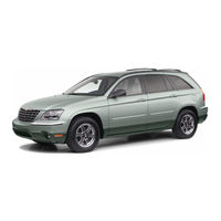
Chrysler 2004 Pacifica Manual (361 pages)
Chrysler VEHICLE manual
Brand:
Chrysler
| Category:
Automobile
| Size: 5.46 MB
Table of Contents
Introduction 1
3
Introduction
1
Table of Contents
3
Introduction
4
How to Use this Manual
4
Warnings and Cautions
6
Vehicle Identification Number
6
Vehicle Modifications / Alterations
7
Things to Know before Starting Your Vehicle
9
A Word about Your Keys
11
Ignition Key Removal
11
Key-In-Ignition Reminder
12
Things to Know before Starting Your Vehicle 9
11
Sentry Key
12
Replacement Keys
14
Sentry Key Programming
14
General Information
15
Illuminated Entry System
15
Door Locks
16
Manual Door Locks
16
Power Door Locks
17
Child Protection Door Lock
18
Remote Keyless Entry
19
To Unlock the Doors and Liftgate
20
To Lock the Doors and Liftgate
21
Using the Panic Alarm
21
General Information
23
Transmitter Battery Service
23
Vehicle Theft Alarm
24
Liftgate
26
Power Liftgate - if Equipped
27
Windows
30
Power Windows
30
Occupant Restraints
31
Lap/Shoulder Belts
32
Lap/Shoulder Belt Untwisting Procedure
38
Seat Belt Pretensioners
40
Enhanced Driver Seat Belt Reminder System (Beltalert™)
40
Seat Belts and Pregnant Women
41
Seat Belt Extender
42
Driver and Front Passenger Supplemental
43
Restraint System - Airbag
43
Side Airbags Supplemental Restraint System (SRS) - if Equipped
50
Child Restraint
53
Engine Break-In Recommendations
61
Safety Tips
62
Exhaust Gas
62
Safety Checks You Should Make Inside the Vehicle
62
Periodic Safety Checks You Should Make Outside the Vehicle
63
Understanding the Features of Your Vehicle
65
Mirrors
69
Inside Day/Night Mirror
69
Automatic Dimming Mirror - if Equipped
70
Driver's Side Outside Mirror Auto Dimmer - if Equipped
70
Exterior Mirrors Folding Feature
70
Outside Mirror - Driver's Side
71
Outside Mirror - Passenger's Side
71
Power Remote-Control Mirrors
72
Heated Remote Control Mirrors
72
Illuminated Vanity Mirrors
73
Hands-Free Communication (Uconnect™) - if Equipped
73
Operation
75
Phone Call Features
79
Advanced Phone Connectivity
81
Uconnect™ System Features
82
Seats
85
10-Way Driver's Power Seat - if Equipped
85
4-Way Passenger's Power Seat
85
Adjustable Head Restraints
86
Heated Seats - if Equipped
86
Memory Seat - if Equipped
88
Understanding the Features of Your Vehicle 65
90
Second Row Manual Seat Recliner
91
Second Row Manual Seat Adjuster
92
Second Row Fold & Tumble Seats
93
Third Row Easy Exit
94
Third Row Seating Flexibility
96
Load Floor
97
Plastic Grocery Bag Retainer
98
Adjustable Pedals - if Equipped
99
To Open and Close the Hood
100
Lights
102
Overhead Console Map/Reading Lights
102
Interior Lights
103
Multi-Function Lever
103
Headlights, Parking Lights, Instrument Panel Lights
103
Automatic Headlights
105
Daytime Running Lights (Canada Only)
105
Lights-On Reminder
105
Headlight Time Delay
105
Fog Lights - if Equipped
106
Turn Signals
106
Highbeam/Lowbeam Select Switch
107
Passing Light
107
Windshield Wipers and Washers
107
Windshield Washers
107
Mist Feature
108
Windshield Wiper Operation
108
Intermittent Wiper System
108
Rear Window Wiper/Washer
108
Tilt Steering Column
110
Traction Control Switch - if Equipped
110
Electronic Speed Control
111
To Activate
112
To Set at a Desired Speed
112
To Deactivate
112
To Resume Speed
113
To Vary the Speed Setting
113
To Accelerate for Passing
113
Overhead Console - if Equipped
114
Courtesy/Reading Lights
114
Sunglasses Storage
115
Garage Door Opener - if Equipped
115
Programming Homelink
116
Canadian Programming/Gate Programming
118
Using Homelink
119
Erasing Homelink Buttons
119
Reprogramming a Single Homelink Button
120
Security
120
Power Sunroof - if Equipped
121
Express Open Feature
122
Wind Buffeting
123
Sunroof Maintenance
123
Electrical Power Outlets
124
Electrical Outlet Use with Engine off
125
Cupholders
126
Front Seat Cupholders
126
Second Row Seat Cupholders
126
Third Row Seat Cupholders
126
Storage
126
Console Features
126
Rear Cargo Storage bin
127
Retractable Cargo Area Cover - if Equipped
127
Cargo Tie-Down Hooks
128
Roof Luggage Rack - if Equipped
130
Load Leveling System
132
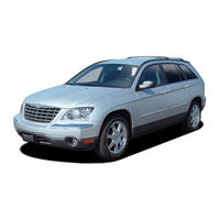
Chrysler 2004 Pacifica Manual (58 pages)
Brand:
Chrysler
| Category:
Automobile
| Size: 0.4 MB
Table of Contents
Table of Contents
1
1 Introduction
3
System Coverage
3
Six-Step Troubleshooting Procedure
3
2 Identification of System
3
3 System Description and Functional Operation
3
Teves Mark 25 System Description
3
Traction Control System (Tcs) Description (if Equipped)
3
System Components
3
Abs and Brake Warning Indicators
4
Controller Antilock Brake (Cab)
4
Hydraulic Control Unit
4
Abs Switches/Sensors
5
Abs Initialization
5
Abs Diagnostic Mode
5
Traction Control Operation (if Equipped)
6
Diagnostic Trouble Codes
6
Freeze Frame
6
Drbiii Error Messages and Blank Screen
6
Drbiii Does Not Power up
6
Display Is Not Visible
6
4 Disclaimers, Safety, Warnings
7
Disclaimers
7
Safety
7
Technician Safety Information
7
Vehicle Preparation for Testing
7
Servicing Sub-Assemblies
7
Drbiii Safety Information
7
Warnings
8
Vehicle Damage Warnings
8
Road Testing a Complaint Vehicle
8
Diagnosis
8
5 Required Tools and Equipment
8
6 Glossary of Terms
8
7 Diagnostic Information and Procedures
11
Battery Voltage out of Range
12
Bcm Messages Not Received
14
Cab Internal Failure
15
Instrument Cluster Bulb Failure
17
Left Front Sensor Circuit Failure
19
Left Rear Sensor Circuit Failure
19
Right Front Sensor Circuit Failure
19
Right Rear Sensor Circuit Failure
19
Left Front Wheel Speed Signal Failure
24
Left Rear Wheel Speed Signal Failure
24
Right Front Wheel Speed Signal Failure
24
Right Rear Wheel Speed Signal Failure
24
MIC Messages Not Received
27
Pci Bus Communication Fault
29
Pci Bus Loopback Failure
32
Pci Bus Shorted to Ground
34
Pci Bus Shorted to Voltage
37
Pci Hardware Failure
40
Pcm Messages Not Received
42
Pump Motor Circuit Failure
44
Communication
46
Response from Controller Antilock Brake
46
Verification Tests
48
Advertisement
Advertisement
Related Products
Chrysler 2004 Crossfire
Chrysler 2004 Sebring Sedan
Chrysler 2004 PT Cruiser
Chrysler 2004 Town and Country
Chrysler 2004 Sebring Coupe
Chrysler 2004 Concorde
Chrysler 2004 LH 300M
Chrysler 2004 Dodge Intrepid
Chrysler 2004 300M
Chrysler 2004 Intrepid
Chrysler Categories
Automobile
Car Video System
Car Receiver
Engine
Car Navigation system
More Chrysler Manuals
Login
Sign In
OR
Sign in with Facebook
Sign in with Google
Upload manual
Upload from disk
Upload from URL