Burkert AE3363 Manuals
Manuals and User Guides for Burkert AE3363. We have 5 Burkert AE3363 manuals available for free PDF download: Quick Start Manual, Operating Instructions Manual
Burkert AE3363 Quick Start Manual (200 pages)
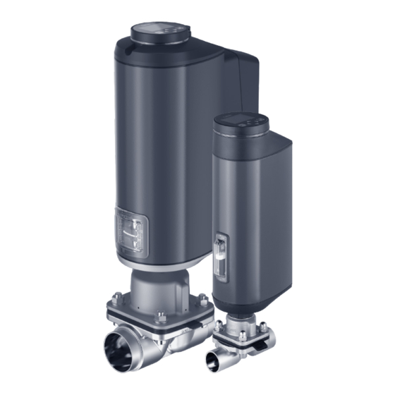
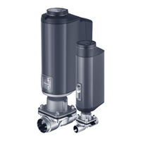
Electromotive diaphragm control valve
Brand: Burkert
|
Category: Control Unit
|
Size: 9 MB
Table of Contents
Advertisement

Burkert AE3363 Operating Instructions Manual (182 pages)
Electromotive diaphragm control valve
Brand: Burkert
|
Category: Control Unit
|
Size: 10 MB
Table of Contents
Burkert AE3363 Operating Instructions Manual (130 pages)
Brand: Burkert
|
Category: Control Unit
|
Size: 3 MB
Table of Contents
Advertisement

Burkert AE3363 Operating Instructions Manual (122 pages)
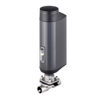
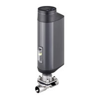
Electromotive diaphragm valve
Brand: Burkert
|
Category: Control Unit
|
Size: 10 MB
Table of Contents
Burkert AE3363 Quick Start Manual (57 pages)
Electromotive diaphragm control valve
Brand: Burkert
|
Category: Control Unit
|
Size: 1 MB