Sign In
Upload
Manuals
Brands
Burkert Manuals
Control Unit
AE3364
Burkert AE3364 Manuals
Manuals and User Guides for Burkert AE3364. We have
2
Burkert AE3364 manuals available for free PDF download: Quick Start Manual
Burkert AE3364 Quick Start Manual (200 pages)
Electromotive diaphragm control valve
Brand:
Burkert
| Category:
Control Unit
| Size: 9 MB
Table of Contents
English
3
Table of Contents
3
1 The Quickstart
4
Definition of Terms
4
Symbols
5
2 Intended Use
6
3 Basic Safety Instructions
6
4 General Notes
8
Contact Address
8
Warranty
8
Information on the Internet
8
5 Structure and Function
8
Structure of the Electromotive Diaphragm Control Valve
8
Display of the Device Status
9
6 Technical Data
10
Standards and Directives
10
Approvals
10
Type Label
10
Labelling Housings
11
Operating Conditions
11
General Technical Data
15
7 Installing the Valve
18
Installation Position of the Diaphragm Control Valves
18
Installation of Devices with Threaded Connection, Flange Connection, Clamp Connection, Bonded Connection
19
Installation of Devices with Welded Connections
20
Install Diaphragm and Actuator
22
Rotating the Actuator
25
Holding Device
26
8 Electrical Installation
26
Electrical Installation with Circular Plug-In Connector
26
Electrical Connection Fieldbus Gateway
31
Electrical Installation with Cable Gland (Only AG2)
33
9 Start-Up
39
Configuration Options for Start-Up
39
Base Settings
39
Set the Safety Position
41
Adjustment of Position Control on AG2
42
Adjustment of Position Control on AG3
44
Set Standard Signal for Set-Point Position
47
Select Physical Unit for Process Control
48
Configure Process Values
48
Scaling the Process Control
49
9.10 Set Dead Band for Process Control
50
Setting up Process Control and Executing P.LIN
50
9.12 Set the Operating State
51
10 Operation
52
Display Elements
52
10.2 Operating Elements
53
Display Operation (Optional)
54
User Interface
54
Description Of Buttons
54
Display Views
55
Description Of Symbols
55
12 Manual Override of Valve
57
Electrical Override Of Valve
57
12.2 Actuating the Valve Mechanically
59
13 Fieldbus Gateway
61
Access To Büs Service Interface
61
14 Maintenance, Troubleshooting
62
Visual Inspection
62
14.2 Replacing the Diaphragm
62
15 Accessories
64
Communications Software
64
16 Cleaning
64
Rinsing the Valve Body
64
17 Disassembly
64
18 Packaging, Transport, Storage
65
19 Disposal
65
Deutsch
66
1 Der Quickstart
67
Begriffsdefinition
67
Darstellungsmittel
68
2 Bestimmungsgemässe Verwendung
69
3 Grundlegende Sicherheitshinweise
69
4 Allgemeine Hinweise
71
Kontaktadresse
71
Gewährleistung
71
Informationen IM Internet
71
5 Aufbau und Funktion
71
Aufbau des Elektromotorischen Membranregelventils
71
Anzeige des Gerätezustands
72
6 Technische Daten
73
Konformität
73
Normen
73
Zulassungen
73
Typschild
73
Beschriftung der Gehäuse
74
Betriebsbedingungen
74
Allgemeine Technische Daten
78
7 Montage des Ventils
81
Einbaulage der Membranregelventile
81
Montage von Geräten mit Gewinde-Muffenanschluss
82
Flanschanschluss, Clamp-Anschluss, Klebeanschluss
82
Montage von Geräten mit Schweißanschluss
83
Membran und Antrieb Montieren
85
Drehen des Antriebs
89
Haltevorrichtung
89
8 Elektrische Installation
90
Elektrische Installation mit Rundsteckverbinder
90
Elektrische Installation mit Kabelverschraubung (nur AG2)
96
9 Inbetriebnahme
101
Einstellmöglichkeiten für die Inbetriebnahme
101
Grundeinstellungen
102
Sicherheitsposition Einstellen
103
Anpassung der Stellungsregelung bei AG2
104
Anpassung der Stellungsregelung bei AG3
107
Normsignal für Sollposition Einstellen
110
Physikalische Einheit für Prozessregelung Wählen
110
Prozesswerte Parametrieren
111
Prozessregelung Skalieren
112
Totband Der Prozessregelung Einstellen
112
Prozessregelung Einrichten P.lin, P.tune Ausführen
113
9.12 Betriebszustand Einstellen
114
10 Bedienung
114
Anzeigeelemente
114
10.2 Bedienelemente
115
11 Displaybedienung (Option)
116
Bedienoberfläche
116
Beschreibung der Tasten
116
Displayansichten
117
Beschreibung der Symbole
117
12 Manuelle Betätigung des Ventils
119
Ventil Elektrisch Betätigen
119
12.2 Ventil Mechanisch Betätigen
121
13 Feldbus-Gateway
124
Zugang Zur Büs-Serviceschnittstelle
124
14 Wartung, Fehlerbehebung
124
Sichtkontrolle
124
14.2 Tausch der Membran
125
15 Zubehör
126
Kommunikations-Software
126
16 Reinigung
127
Spülen Des Ventilgehäuses
127
17 Demontage
127
18 Verpackung, Transport, Lagerung
127
19 Entsorgung
127
Français
130
1 Quickstart
131
Définition des Termes
131
Symboles
132
2 Utilisation Conforme
133
3 Consignes de Sécurité Fondamentales
133
4 Remarques Générales
135
Adresse de Contact
135
Garantie
135
Informations Sur Internet
135
5 Structure et Fonction
136
Structure de la Vanne de Régulation à Membrane Électromotorisée
136
Affichage de L'état de L'appareil
136
6 Caractéristiques Techniques
137
Normes et Directives
137
Certifications
137
Type Label
138
Étiquetage des Boîtiers
138
Conditions D'exploitation
139
Caractéristiques Techniques Générales
142
7 Installation de la Vanne
146
Position de Montage de la Vanne de Régulation à Membrane
146
Montage des Appareils Avec Raccord Fileté à Manchon, Raccord à Bride, Raccord Clamp et Raccord Adhésif
148
Installation des Appareils Avec Raccord Soudé
149
Assembler la Membrane et L'actionneur
150
Rotation de L'actionneur
154
Dispositif de Fixation
155
8 Installation Électrique
155
Installation Électrique Avec Connecteur Rond
155
Raccordement Électrique de la Passerelle de Bus de Terrain
161
Installation Électrique Avec Presse- Étoupe (AG2 Uniquement)
162
9 Mise en Service
168
Possibilités de Réglage pour la Mise en Service
168
Réglages de Base
169
Régler la Position de Sécurité
171
Adaptation de la Régulation de Position pour AG2
172
Adaptation de la Régulation de Position pour AG3
175
Régler le Signal Normalisé pour la Position de Consigne
178
Sélectionner L'unité Physique pour la Régulation de Process
178
Paramétrer les Valeurs de Process
179
Mettre à L'échelle la Régulation de Process
180
Régler la Bande Morte de la Régulation de Process
180
Configurer la Régulation du Process P.LIN, Exécuter
181
9.12 Configurer L'état de Marche
182
10 Commande
182
Éléments D'affichage
182
10.2 Éléments de Commande
183
11 Commande Par Affichage (Option)
184
Interface Utilisateur
184
Description des Touches
185
Fenêtres De L'écran
185
Description des ICônes
186
12 Commande Manuelle de la Vanne
187
Actionner la Vanne Avec la Commande Électrique
187
Actionner la Vanne Avec la Commande Mécanique
190
13 Passerelle de Bus de Terrain
193
Accès À L'entrée Maintenance Büs
193
14 Maintenance, Dépannage
194
Contrôle Visuel
194
14.2 Remplacement de la Membrane
194
15 Accessoires
196
Logiciel de Communication
196
16 Nettoyage
196
Rinçage du Corps de Vanne
196
17 Démontage
197
18 Emballage, Transport, Stockage
197
19 Élimination
198
Advertisement
Burkert AE3364 Quick Start Manual (57 pages)
Electromotive diaphragm control valve
Brand:
Burkert
| Category:
Control Unit
| Size: 1 MB
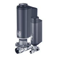
Table of Contents
Table of Contents
3
1 The Quickstart
4
Definition of the Term "Device
4
Symbols
5
2 Intended Use
5
3 Basic Safety Instructions
6
4 General Information
7
Contact Address
7
Warranty
7
Information on the Internet
7
5 Structure And Function
8
Structure of the Electromotive Diaphragm Control Valve
8
Display of the Device State
8
6 Technical Data
9
Conformity
9
Standards
9
Licenses
9
Rating Plate
9
Labeling of the Bodies
10
Operating Conditions
10
General Technical Data
13
7 Installation Of The Valve
16
Installation Position of the Diaphragm Control Valves
17
Installation of Devices with Socket Connection, Flanged Connection, Clamp Connection or Bond Connection
18
Installation of Devices with Welded Connection
18
Installing Diaphragm and Actuator
20
Rotating the Actuator
23
Holding Device
24
8 Electrical Installation
25
Electrical Installation with Circular Plug-In Connector
25
Electrical Installation with Cable Gland
28
9 Start-Up
34
Setting Options for Start-Up
34
Basic Settings
34
Setting Safety Position
35
Adjust the Position Control - Running M.Q0.TUNE
36
Set Standard Signal for Set-Point Position
39
Select Physical Unit for Process Control
39
Parameterize Process Values
40
Scaling Process Control
41
Setting Dead Band of the Process Control
41
Set up Process Control - Run P.LIN
42
Setting Operating State
42
10 Operation
43
Display Elements
43
Control Elements
44
Dip Switches
44
11 Display Operation (Option)
45
User Interface
45
Description of the Keys
45
Display Views
46
Description of the Symbols
46
12 Manual Actuation Of The Valve
48
Actuating Valve Electrically
48
Actuating Valve Mechanically
50
13 Fieldbus Gateway
51
Technical Data
51
Electrical Connection
52
Access to the Büs Service Interface
52
14 Maintenance, Troubleshooting
53
Visual Inspection
53
Replacing the Diaphragm
53
15 Accessories
55
Communications Software
55
16 Cleaning
55
17 Disassembly
55
18 Packaging, Transport, Storage
56
19 Disposal
56
Advertisement
Related Products
Burkert AE3360
Burkert AE3361
Burkert AE3365
Burkert AE3363
Burkert AE3320
Burkert AE3321
Burkert AE3323
Burkert AE3324
Burkert AE3325
Burkert AE33
Burkert Categories
Control Unit
Controller
Measuring Instruments
Transmitter
Accessories
More Burkert Manuals
Login
Sign In
OR
Sign in with Facebook
Sign in with Google
Upload manual
Upload from disk
Upload from URL