Burkert 3323 Operating Instructions Manual
Hide thumbs
Also See for 3323:
- Operating instructions manual (122 pages) ,
- Quick start manual (44 pages) ,
- Quick start manual (150 pages)
Table of Contents
Advertisement
Quick Links
Advertisement
Table of Contents
Troubleshooting

Related Manuals for Burkert 3323


Summary of Contents for Burkert 3323
- Page 1 Type 3323, 3324, 3325 AE3363 Electromotive diaphragm valve Operating instructions...
- Page 2 We reserve the right to make technical changes without notice. Technische Änderungen vorbehalten. Sous réserve de modifications techniques. © 2016 – 2019 Bürkert Werke GmbH & Co. KG Operating Instructions 1910/03_EN-en_00810538 / Original DE...
-
Page 3: Table Of Contents
Type 3323, 3324, 3325 Electromotive diaphragm valve ontents THE OPERATING INSTRUCTIONS ......................7 Symbols ............................7 1.2 Definitions of terms ........................7 INTENDED USE ............................8 BASIC SAFETY INSTRUCTIONS ......................9 GENERAL INFORMATION ........................11 4.1 Contact address .........................11 4.2 Warranty .............................11 4.3 Information on the Internet ......................11 PRODUCT DESCRIPTION ........................12 5.1 General description ........................12... - Page 4 Type 3323, 3324, 3325 8.3 Licenses .............................23 8.4 Type label ...........................23 8.5 Labelling of the forged steel valve bodies ................24 8.6 Labelling of the tube valve bodies (VP) ..................24 8.7 Operating conditions .........................25 8.8 General technical data .......................28 8.9 Electrical data ..........................28 8.10 Flow values for forged steel valve bodies VS ................31 8.11 Flow values for cast valve bodies and plastic valve bodies ............32 8.12 Flow values for tube valve bodies .....................33 INSTALLATION OF THE VALVE ......................34 9.1 Safety instructions for installation .....................34...
- Page 5 Type 3323, 3324, 3325 OPERATION ............................64 12.1 Overview: Availability of the operating elements..............64 12.2 Display elements ..........................65 12.3 Control elements ........................66 12.4 büS service interface .........................67 12.5 Accepting and saving SIM card data (option) ................... 68 12.6 User interface of the Bürkert Communicator PC software............... 69 12.7 Establishing a connection between the device and Bürkert Communicator ......70 BASIC FUNCTIONS ..........................71 13.1 Switching operating state, AUTOMATIC – MANUAL ..............71 13.2 Setting safety position and effective direction .................72 EXTENDED FUNCTIONS ..........................73 14.1 X.TIME – Limiting the control speed ..................73...
- Page 6 Type 3323, 3324, 3325 büS ..............................100 19.1 Cabling of büS networks ......................100 19.2 Configuration of büS networks ....................100 MAINTENANCE, TROUBLESHOOTING .....................101 20.1 Visual inspection ........................101 20.2 Replacing the diaphragm ......................102 20.3 Replacing the SAFEPOS energy pack ..................108 20.4 Maintenance messages ......................119 TROUBLESHOOTING AND MESSAGES ...................120 21.1 Error messages ........................120 21.2 Messages for device status “Out of specification” ..............122 21.3 Messages for device status “Function check” ...............123 CLEANING ............................124 22.1 Flushing the valve body ......................124...
-
Page 7: The Operating Instructions
MENUE Representation of software interface text. Definitions of terms • The term “device” used in these instructions applies to the electromotive diaphragm valve of Types 3323, 3324, 3325 and AE3363. • In these instructions, the abbreviation “Ex” stands for “explosion-risk”. -
Page 8: Intended Use
Type 3323, 3324, 3325 Intended use INTENDED USE Non-authorized use of the electromotive diaphragm valve of Types 3323, 3324 and 3325 may be a hazard to people, nearby equipment and the environment. The electromotive diaphragm valve of Types 3323, 3324 and 3325 is designed to control the flow of liquid and gaseous media. ▶ Standard model devices must not be used in the potentially hazardous area. They do not have a sepa- rate Ex type label which indicates approval for the explosion-proof area. -
Page 9: Basic Safety Instructions
Type 3323, 3324, 3325 Basic safety instructions BASIC SAFETY INSTRUCTIONS These safety instructions do not consider any contingencies or incidents which occur during installation, operation and maintenance. The operator is responsible for observing the location-specific safety regulations, also with reference to the personnel. - Page 10 Type 3323, 3324, 3325 Basic safety instructions ▶ Devices without a separate Ex type label may not be used in a potentially explosive area. ▶ Only feed in the media types specified in chapter “8 Technical data” to the media connections.
-
Page 11: General Information
The warranty is only valid if the device is used as intended in accordance with the specified application conditions. Information on the Internet Operating instructions and data sheets for Types 3323, 3324 and 3325 can be found on the Internet at: www.buerkert.com english... -
Page 12: Product Description
PRODUCT DESCRIPTION General description The electromotive diaphragm valve Type 3323, 3324 and 3325 is suitable for the control of flow rate of liquid and gaseous media. These can be neutral, ultra-pure, sterile as well as contaminated, aggressive or abrasive media of high to low viscosity. -
Page 13: Variants
Type 3323, 3324, 3325 Product description Variants The following variants are described in these instructions: • Type 3323: 2-way body • Type 3324: T-body • Type 3325: tank bottom body Options • Energy pack (SAFEPOS energy-pack) for approaching the safety position. -
Page 14: Structure And Function
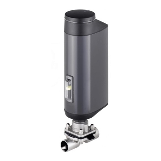
Actuator housing Pressure compensation element Transparent window with Do not unscrew! position indicator FE functional ground Actuator base 2 Relief bores Diaphragm socket Diaphragm Valve body Port connection Figure 1: Structure, electromotive diaphragm valve with 2-way body, Type 3323 english... - Page 15 Type 3323, 3324, 3325 Structure and function 6.1.2 T-body Dummy cover or display with illuminated display and bayonet catch Actuator cove Actuator housing Transparent window with position indicator Actuator base 2 Relief bores Diaphragm socket Diaphragm Valve body Port connection...
-
Page 16: Valve Position After Failure Of The Supply Voltage
Type 3323, 3324, 3325 Structure and function Valve position after failure of the supply voltage Valve position when using devices without the SAFEPOS energy-pack: If the electromotive actuator is at a standstill due to failure of the supply voltage, the valve remains in the last occupied position. If the supply voltage fails while the actuator is changing the valve position, the valve stops in an undefined position. -
Page 17: Display Of The Device Status
Type 3323, 3324, 3325 Structure and function Display of the device status The device status is indicated at the LED illuminated ring. To indicate the device status and the valve position, different LED modes can be set: • Valve mode •... - Page 18 Type 3323, 3324, 3325 Structure and function 6.4.3 NAMUR mode In NAMUR mode, the LED illuminated ring lights up according to NAMUR NE 107, in the colour specified for the device status. If several device statuses exist simultaneously, the device status with the highest priority is displayed. The priority is determined by the severity of the deviation from standard operation (red = failure = highest priority).
-
Page 19: Factory Settings
Type 3323, 3324, 3325 Structure and function 6.4.5 Device status messages Device status messages and error messages are recorded in the logbook. Chapter “20 Maintenance, trou- bleshooting” describes the most common messages and the required measures. Device status messages for „Function check“ The messages are output when operation is interrupted by work on the device. -
Page 20: Electrical Control
Type 3323, 3324, 3325 Electrical control ELECTRICAL CONTROL Function The position of the actuator (stroke) is controlled by the digital input. The position is specified either by an external signal (analogue) or via a fieldbus (digital). The position sensor detects the actual position of the electrical linear actuator and generates an end position signal via the digital outputs. - Page 21 Type 3323, 3324, 3325 Electrical control 7.1.2 Function diagram External Control 2 end position signals position signal Actual position Motor Gears Position sensor Valve (actuator) Figure 5: Function diagram english...
-
Page 22: Safepos Energy-Pack (Option)
Type 3323, 3324, 3325 Electrical control SAFEPOS energy-pack (option) Optionally there is the energy pack (SAFEPOS energy-pack) for the device. In the event of a supply voltage failure, the energy storage system supplies the actuator with the energy required to move the valve to the safety position. -
Page 23: Technical Data
• Port connection • Maximum permitted medium pressure Conformity The electromotive valves, Types 3323, 3324 and 3325, are compliant with EU directives as stated in the EU Declaration of Conformity (if applicable). Standards The applied standards, which are used to demonstrate conformity with the EU Directives, are listed in the EU type examination certificate and/or the EU Declaration of Conformity (if applicable). -
Page 24: Labelling Of The Forged Steel Valve Bodies
Type 3323, 3324, 3325 Technical data 8.4.1 UL additional label (example) Type AE3363 Power Supply SELV / PELV only! LISTED Process Control Equipment E238179 Figure 7: UL additional label (example) Labelling of the forged steel valve bodies Depending on the variant, the labelling may vary. -
Page 25: Operating Conditions
Type 3323, 3324, 3325 Technical data Operating conditions For operation of the device observe the product-specific information on the type label. WARNING! Malfunction if the temperature exceeds or drops below the permitted temperature range. ▶ Never expose the device outdoors to direct sunlight. ▶ The temperature must not exceed or drop below the permitted ambient temperature range. Reduced sealing function if medium pressure too high. As the valve seat is closed against the medium flow, the medium pressure may become too high and prevent the valve seat from closing tightly. - Page 26 Type 3323, 3324, 3325 Technical data 8.7.2 Permitted medium temperature ATTENTION! The behavior of the medium with respect to the diaphragm materials may change depending on the medium temperature. ▶ The indicated medium temperatures apply only to media which do not corrode or swell the diaphragm materials.
- Page 27 Type 3323, 3324, 3325 Technical data Graph of pressure for orifices (DN) 15 to 40: DN 15 - 40 PVDF 20 40 60 80 100 120 140 Temperature [°C] Figure 10: Graph: Dependence on medium temperature and medium pressure for valve bodies made of plastic 8.7.3...
-
Page 28: General Technical Data
Type 3323, 3324, 3325 Technical data General technical data Dimensions: See data sheet Weight: See data sheet Materials: Actuator: PPS and aluminium powder-coated Valve body: Metal: stainless steel board material (Types 3324 and 3325), Investment casting (VG), forged steel (VS),... - Page 29 Type 3323, 3324, 3325 Technical data ATTENTION! Consider voltage drop in supply line. Example: with a cable cross-section of 0.34 mm2 a copper cable may have a maximum length of 8 meters. Operating voltage: 24 V ± 10 % max. residual ripple 10 % Operating current [A]*: max.
- Page 30 Type 3323, 3324, 3325 Technical data Service life energy pack SAFEPOS energy-pack Charging time: maximum 100 seconds (depending on the conditions of use) Service life: up to 10 years (depending on the conditions of use). The determined service life of 7.5 years was determined under the following...
-
Page 31: Flow Values For Forged Steel Valve Bodies Vs
Type 3323, 3324, 3325 Technical data 8.10 Flow values for forged steel valve bodies VS Kvs values for forged steel valve bodies VS Kvs value [m Diaphragm Orifice con- Seal size nection (DN) material ASME EPDM PTFE EPDM 8 / 1/4" PTFE EPDM 10 / 3/8" PTFE EPDM 15 / 1/2“... -
Page 32: Flow Values For Cast Valve Bodies And Plastic Valve Bodies
Type 3323, 3324, 3325 Technical data 8.11 Flow values for cast valve bodies and plastic valve bodies Kvs values for cast valve bodies VG and plastic valve bodies PD, PP, PV Kv value [m Orifice con- Diaphragm size Seal material Cast valve bodies VG Plastic valve bodies nection (DN) (all standards) (all materials) EPDM 0.95 PTFE EPDM PTFE EPDM 10.7 PTFE 10.5 EPDM 14.6 11.4 PTFE 13.6... -
Page 33: Flow Values For Tube Valve Bodies
Type 3323, 3324, 3325 Technical data 8.12 Flow values for tube valve bodies Kvs values for 3G tube valve bodies VP (IHU2) Kv value [m Orifice con- Diaphragm size Seal material nection (DN) ASME EPDM 8 / 1/4" PTFE EPDM 10 / 3/8“ PTFE EPDM 15 / 1/2“ PTFE EPDM 15 / 1/2“ PTFE EPDM 20 / 3/4“... -
Page 34: Installation Of The Valve
Type 3323, 3324, 3325 Installation of the valve INSTALLATION OF THE VALVE Safety instructions for installation WARNING! Risk of injury from improper assembly. ▶ The assembly may be carried out only by trained technicians and with the appropriate tools. ▶ Secure system against unintentional activation. - Page 35 Type 3323, 3324, 3325 Installation of the valve Mark for self-draining upwards Inclination α angle of the pipeline 1° – 5° Figure 13: Installation position for self-drainage of the body Information about self-draining on the Internet. If the self-drainage angle is not specified on the valve body, please refer to the additional manual “Angle specifications for self-draining“...
- Page 36 Type 3323, 3324, 3325 Installation of the valve 9.2.3 Installation position of tank bottom body Recommended installation position: any, preferably with actuator face down. Figure 15: Installation position of tank bottom body, Type 3325 english...
-
Page 37: Installation Of Devices With Threaded Socket Connection, Flange Connection, Clamp Connection Or Bond Connection
Type 3323, 3324, 3325 Installation of the valve Installation of devices with threaded socket connection, flange connection, clamp connection or bond connection ATTENTION! Damage to the diaphragm. ▶ To prevent damage, the valve must be in MANUAL operating state during installation. Devices are delivered with the MANUAL operating state preset. - Page 38 Type 3323, 3324, 3325 Installation of the valve → Connect valve body to pipeline. Ensure installation is de-energised and low-vibration. Holding device To protect the valve actuator from damage due to forces and vibrations, a holding device is recom- mended. This is available as an accessory. See chapter “23 Accessories, spare parts”.
-
Page 39: Installation Of Devices With Welded Connection
Type 3323, 3324, 3325 Installation of the valve Installation of devices with welded connection ATTENTION! Observe the national regulations for the qualification of welders and for performing welding work. For devices with a tank bottom body, special measures must be observed when they are welded in. - Page 40 Type 3323, 3324, 3325 Installation of the valve 9.4.2 Required tools and equipment • Allen key, width across flats 3 mm Only required when no supply voltage is applied to the device in order to move the valve into the open position.
- Page 41 Type 3323, 3324, 3325 Installation of the valve 9.4.4 Welding tank bottom body Precondition: The actuator and diaphragm must be removed from the valve body. DANGER! Risk of injury from high pressure! ▶ Before working on the system, switch off the pressure and vent or drain lines. Recommendations Observe sequence: 1. Weld the tank bottom body onto the base of the tank before installing the tank.
-
Page 42: Mounting Actuator On Valve Body
Type 3323, 3324, 3325 Installation of the valve Next steps: • If the diaphragm is not mounted, mount it on the actuator, chapter “9.5.3”, page 42. • Mount the actuator onto the valve body and connect the power, chapter “9.5.4”, page 44. - Page 43 Type 3323, 3324, 3325 Installation of the valve → If there is no insert in the pressure piece, fit the insert into the pressure piece as shown in the figure. Pressure piece Insert Pressure piece with insert fitted in Figure 16: Fitting the insert into the pressure piece →...
- Page 44 Type 3323, 3324, 3325 Installation of the valve 9.5.4 Mounting actuator on the valve body and making the electrical connections WARNING! Risk of injury due to electric shock. Risk of crushing due to mechanically moving parts. ▶ Switch off supply voltage. ATTENTION! Damage to the diaphragm. ▶ To prevent damage, the device must be in MANUAL operating state during installation.
- Page 45 Type 3323, 3324, 3325 Installation of the valve Release dummy CLOSE button cover OPEN button Figure 18: Running M.SERVICE → To release, rotate the dummy cover counter-clockwise and remove it. → Simultaneously hold down the OPEN and CLOSE buttons for 5 s.
-
Page 46: Rotating The Actuator
Type 3323, 3324, 3325 Installation of the valve Next steps: • To adjust the position control, running the M.Q0.TUNE function, chapter “11.3”, page 61. ATTENTION! Damage to the diaphragm. ▶ To prevent damage, first run the M.Q0.TUNE function after making the electrical connection. Only then set the operating state to AUTOMATIC. -
Page 47: Removing The Actuator
Type 3323, 3324, 3325 Installation of the valve Removing the actuator DANGER! Risk of injury from high pressure. ▶ Before working on the system or device, switch off the pressure and vent or drain lines. WARNING! Risk of injury due to improper installation work. ▶ The actuator may be removed only by trained technicians and with the appropriate tools. - Page 48 Type 3323, 3324, 3325 Installation of the valve Actuator Diaphragm socket Nuts (4 units) Diaphragm Valve body Body screws (4 units) Figure 20: Disassembly of the diaphragm using the 2-way body as an example → Remove the body screws. →...
-
Page 49: Holding Device
Type 3323, 3324, 3325 Installation of the valve Holding device The holding device is used to protect the valve actuator and the body from damage due to forces and oscil- lations. The holding device is available as an accessory. See chapter “23 Accessories, spare parts”... -
Page 50: Electrical Installation
Type 3323, 3324, 3325 Electrical installation ELECTRICAL INSTALLATION The electromotive valve is available with one of 2 different connection variants: • With circular plug-in connector (multipole version) • Cable gland with connection terminals Signal values Operating voltage: 24 V Digital input for control signal: 0...5 V = log „0“;... - Page 51 Type 3323, 3324, 3325 Electrical installation 10.1.1 Description of the circular plug-in connectors X3 – circular plug M12, 5-pole operating voltage X1 – circular plug M12, 8-pin input and output signals FE functional ground Figure 22: Description of the circular plug-in connectors 10.1.2 X1 – M12 circular plug, 8-pin Wire color* Assignment (from point of view of the device) Input signals from the control center (e.g. PLC)
-
Page 52: Electrical Connection Büs/Canopen
Type 3323, 3324, 3325 Electrical installation 10.1.3 X3 – M12 circular plug, 5-pole, operating voltage (Devices without büS/CANopen network) A 4-pin female connector can be used as a counterpart. Pin Wire color* Assignment do not connect white +24 V ± 10 %, max. residual ripple 10 %... -
Page 53: Electrical Connection Fieldbus Gateway
Type 3323, 3324, 3325 Electrical installation 10.3 Electrical connection fieldbus gateway Fieldbus gateway Fieldbus connection M12 (2 Port Ethernet Switch) Figure 23: Electrical connection fieldbus gateway The fieldbus gateway is connected with a circular plug-in connector M12, 4-pin. Circuit diagram Assignment... -
Page 54: Electrical Installation With Cable Gland
Type 3323, 3324, 3325 Electrical installation 10.4 Electrical installation with cable gland WARNING! Risk of injury from improper installation. ▶ Installation may be carried out by authorized technicians only and with the appropriate tools. ▶ Observe the general rules of technology during installation. Risk of injury from unintentional activation of the system and uncontrolled restart. ▶ Secure system against unintentional activation. - Page 55 Type 3323, 3324, 3325 Electrical installation 2. Removing the LED and storage module: Fastening screws Metal housing of the LED and storage module Figure 26: Removing the LED and storage module → Remove the 2 fastening screws (hexalobular-internal screws T20). → Take hold of the LED and storage module on both sides of the metal housing and lift out.
- Page 56 Type 3323, 3324, 3325 Electrical installation 10.4.2 Connecting the cables → Push the cables through the cable gland. ATTENTION! Allow for connection to spring-type terminals. ▶ Minimum length of the wire end ferrule: 8 mm ▶ Maximum cross-section of the wire end ferrule: 1.5 mm (without collar), 0.75 mm...
- Page 57 Type 3323, 3324, 3325 Electrical installation 10.4.3 Terminal assignment – input signal from the control centre (e.g. PLC) Terminal Assignment (from point of view of the device) 0...5 V (log. 0) Digital input + 10...30 V (log. 1) Digital input GND specific to operating voltage GND (terminal GND)
- Page 58 Type 3323, 3324, 3325 Electrical installation 10.4.5 Closing the actuator housing ATTENTION! Damage or malfunction due to ingress of dirt and moisture. Before closing the device, comply with the degree of protection IP65 and IP67 by ensuring that: ▶ The seal must be inserted in the actuator housing/actuator cover and must not be damaged.
- Page 59 Type 3323, 3324, 3325 Electrical installation → Carefully press down the LED and storage module by hand. The end position is reached if the upper edge of the module is fully and evenly recessed in the actuator cover. NOTE! The plug connection will be damaged if the LED and storage module is not correctly inserted.
-
Page 60: Start-Up
Type 3323, 3324, 3325 Start-up START-UP WARNING! Risk of injury due to improper operation. Improper operation may result in injuries as well as damage to the device and the surrounding area. ▶ The operating personnel must know and have understood the contents of the operating instructions. -
Page 61: Adjusting The Position Control - Running M.q0.Tune
Type 3323, 3324, 3325 Start-up 11.3 Adjusting the position control - running M.Q0.TUNE When the M.Q0.TUNE function is running, the position control is adjusted to the actual stroke of the actuator used and the required sealing force is determined. In doing so, the sealing point must be manually approached. It is important that the valve is not completely closed. - Page 62 Type 3323, 3324, 3325 Start-up 11.3.1 Triggering the M. Q0.TUNE function The 2 buttons for approaching the sealing point and for running the M.Q0.TUNE are under the dummy cover. Release dummy CLOSE button cover OPEN button Figure 31: Adjustment of the position control using the buttons in the device →...
-
Page 63: Setting Automatic Operating State
Type 3323, 3324, 3325 Start-up 11.4 Setting AUTOMATIC operating state Factory settings: Devices are delivered with the MANUAL operating state preset. The operating state is switched with DIP switch 4 which is located under the dummy cover. Devices with ATEX approval or IECEx approval are secured with a magnetic lock. -
Page 64: Operation
Type 3323, 3324, 3325 Operation OPERATION WARNING! Danger due to improper operation. Improper operation may result in injuries as well as damage to the device and the area around it. ▶ The operating personnel must know and have understood the contents of the operating instructions. -
Page 65: Display Elements
Type 3323, 3324, 3325 Operation 12.2 Display elements Representation of the display elements: LED illuminated ring 4 verschiedene LED-Modi einstellbar Mechanical Open valve position indicator Close valve Figure 32: Display elements 12.2.1 LED illuminated ring The transparent LED illuminated ring, which transmits the light of the LEDs outwards, is attached to the dummy cover. -
Page 66: Control Elements
Type 3323, 3324, 3325 Operation 12.3 Control elements Representation of the control elements: SIM card DIP switches büS Service interface CLOSE button OPEN button Mechanical manual control Figure 33: Control elements 12.3.1 DIP switches Settings Switch 1: Activate or deactivate safety position. See chapter “13.2 Setting safety position and effective direction”. -
Page 67: Büs Service Interface
Type 3323, 3324, 3325 Operation 12.4 büS service interface The büS service interface can be used for a short-term service. • Configuration of the device, e.g. the basic setting for starting up using the „Bürkert Communicator“ PC software. To do this, the USB-büS-interface set, available as an accessory, is required. -
Page 68: Accepting And Saving Sim Card Data (Option)
Type 3323, 3324, 3325 Operation 12.5 Accepting and saving SIM card data (option) The optionally available SIM card can be used to save and transfer device-specific values and user settings to a different device. The SIM card is detected when the device starts and is checked for available data. If applicable, this data is accepted or overwritten: •... -
Page 69: User Interface Of The Bürkert Communicator Pc Software
Type 3323, 3324, 3325 Operation 12.6 User interface of the Bürkert Communicator PC software View of configuration area: Navigation area Menu bar Add interface (connect to büS stick) COMMUNICATOR Edit File Device View Options Tools Help Position Controller Start page Parameter Diagnostics Maintenance... -
Page 70: Establishing A Connection Between The Device And Bürkert Communicator
Type 3323, 3324, 3325 Operation View of application area: Current user level COMMUNICATOR File Device Edit View Options Tools Help 0029671400000001 E_Process_Valve 3323 Start page Position controller Desktop 73,7 % Graph büS Inputs / Outputs 0029671400000001 E_Process_Valve 3323 Position controller Inputs / Outputs General settings... -
Page 71: Basic Functions
Type 3323, 3324, 3325 Basic functions BASIC FUNCTIONS The basic functions are set via the DIP switch position. DIP switches Basic function Activate or deactivate safety position DIP switches Set safety position and effective direction (NC and NO) Not used For switching between AUTOMATIC mode and MANUAL mode. -
Page 72: Setting Safety Position And Effective Direction
Type 3323, 3324, 3325 Basic functions 13.2 Setting safety position and effective direction The effective direction and the safety position are set using DIP switches 1 and 2. DIP switch 2 DIP switch 1 Switch position Set-point value Effective Switch Safety position (Safety position (0...5 V) (10...30 V) -
Page 73: Extended Functions
Type 3323, 3324, 3325 Extended functions EXTENDED FUNCTIONS 14.1 X.TIME – Limiting the control speed Use this auxiliary function to specify the opening and closing times for the entire stroke and limit the control speeds. When the M.Q0.TUNE function is running, the minimum opening and closing time for the entire stroke is automatically entered for Open and Close. - Page 74 Type 3323, 3324, 3325 Extended functions Configuring the limit actuating time: → In the detailed view parameter select X.TIME. → Select Opening time. → Input and confirm lower limit value. → Select Closing time. → Input and confirm upper limit value. You have activated and configured the limit actuating time.
-
Page 75: Limit - Limiting The Mechanical Stroke Range
Type 3323, 3324, 3325 Extended functions 14.2 X.LIMIT – Limiting the mechanical stroke range This auxiliary function limits the (physical) stroke to specified percentage values (minimum and maximum). In doing so, the stroke range of the limited stroke is set equal to 100 %. -
Page 76: Setting Led Mode
Type 3323, 3324, 3325 Extended functions Configuring the mechanical stroke limit: → In the detailed view parameter select X.LIMIT. → Select Maximum. → Input and confirm upper limit value. You have activated and configured the mechanical stroke limit. 14.3 Setting LED mode Setting with the PC software Bürkert Communicator on the PC: The PC software Bürkert Communicator can be downloaded free of charge from the Bürkert homepage. -
Page 77: Setting The Colours For Indicating The Valve Position
Type 3323, 3324, 3325 Extended functions 14.4 Setting the colours for indicating the valve position The colours on the LED light ring that indicate the valve positions can be set individually. Setting with the PC software Bürkert Communicator on the PC: The PC software Bürkert Communicator can be downloaded free of charge from the Bürkert homepage. -
Page 78: Manual Actuation Of The Valve
Type 3323, 3324, 3325 Manual actuation of the valve MANUAL ACTUATION OF THE VALVE The valve can be manually actuated in 2 ways: electrically or mechanically. Electrical manual control should usually be used to open and close the valve manually. - Page 79 Type 3323, 3324, 3325 Manual actuation of the valve Changing to the operating state AUTOMATIC: → Reset DIP switch 4 downwards. The device is back in the AUTOMATIC operating state. Closing dummy cover → Mount the dummy cover and turn it clockwise until the 2 marks (one vertical line on the dummy cover and on the fieldbus gateway) are vertically aligned.
-
Page 80: Actuating Valve Mechanically
Type 3323, 3324, 3325 Manual actuation of the valve 15.2 Actuating valve mechanically When the supply voltage is not applied, e.g. during installation or in the event of a power failure, the valve can be opened or closed with the mechanical manual control. - Page 81 Type 3323, 3324, 3325 Manual actuation of the valve 15.2.3 Removing dummy cover Devices with ATEX approval or IECEx approval are secured with a magnetic lock. The removal of the cover is described in the additional manual for electromotive control valves with ATEX approval and IECEx approval. Release dummy cover Figure 42: Removing dummy cover or display module →...
- Page 82 Type 3323, 3324, 3325 Manual actuation of the valve 15.2.5 Actuating valve mechanically NOTE! The mechanical manual override may be used only when it is deenergised, otherwise the device may be damaged. → To mechanically actuate the valve, use an Allen key with width across flats 3 mm.
- Page 83 Type 3323, 3324, 3325 Manual actuation of the valve 15.2.6 Mounting the fieldbus gateway on the actuator Preconditions: Supply voltage switched off. NOTE! The fieldbus gateway may be mounted only when it is deenergised, otherwise the device may be damaged. Align and position fieldbus gateway.
-
Page 84: Operating Structure / Factory Setting
Type 3323, 3324, 3325 Operating structure / factory setting OPERATING STRUCTURE / FACTORY SETTING The factory presets are highlighted in blue to the right of the menu in the operating structure. Examples: Menu options activated or selected at the factory Menu options not activated or selected at the factory sec, ... - Page 85 Type 3323, 3324, 3325 Operating structure / factory setting Position controller MAINTENANCE CALIBRATION M.CLEAN Figure 47: Operating structure - 1-b, Maintenance position controller Position controller DIAGNOSTICS SYSTEM.VALUES Operation time Travel accumulator Direction change Device temperature Highest temperature Lowest temperature HISTOGRAM.POS HISTOGRAM.SPAN...
- Page 86 Type 3323, 3324, 3325 Operating structure / factory setting Position controller DIAGNOSTICS USER.DIAGNOSIS ADD.DIAGNOSE SERVICE.TIME TRAVEL.ACCU CYCLE.COUNTER POS.MONITOR HISTOGRAM.POS HISTOGRAM.SPAN SERVICE.TIME Operation time Interval Next message TRAVEL.ACCU Travel accumulator Interval Next message CYCLE.COUNTER Direction change Interval Next message POS.MONITOR Tolerance band...
- Page 87 Type 3323, 3324, 3325 Operating structure / factory setting Inputs / Outputs PARAMETER Digital CMD.source büS ADDITIONAL IO´s DIGITAL OUT 1 FUNCTION Position limit DIGITAL OUT 2 Device state Manul mode Safepos Position Limit Device State Maintenance Out of specification...
- Page 88 Type 3323, 3324, 3325 Operating structure / factory setting General settings PARAMETER Mode Status LED NAMUR mode Valve mode Valve mode + warnings LED off Gelb Valve open Grün Valve closed Grün Valve in between büS Displayed name Location Description...
- Page 89 Type 3323, 3324, 3325 Operating structure / factory setting General settings PARAMETER Diagnostics PDO-Configuration PDO 1 PDO 2 PDO 3 Multiplexed PDO Reset to default values Figure 52: Operating structure - 3-b, Configuration area general settings General settings MAINTENANCE Device information Displayed name Ident.
- Page 90 Type 3323, 3324, 3325 Operating structure / factory setting General settings DIAGNOSTICS Device status Operating duration Device temperature Supply voltage Min./Max. values Max. temperature Transferable memory status Min. temperature Max. supply voltage Min. supply voltage Receive errors büS status Receive errors max.
-
Page 91: Industrial Ethernet
Type 3323, 3324, 3325 Industrial Ethernet INDUSTRIAL ETHERNET For integration into an Ethernet network, the electromotive diaphragm valve with integrated fieldbus gateway is available as an option. Supported fieldbus protocols: EtherNet/IP, PROFINET, Modbus TCP. 17.1 Description fieldbus gateway Fieldbus gateway Fieldbus connection M12... - Page 92 Type 3323, 3324, 3325 Industrial Ethernet 17.1.2 LEDs for status display of the network connection The LEDs for status display of the network connection are inside the fieldbus gateway. To gain access, open the cover by turning it anticlockwise. Interfaces X1 and X2...
-
Page 93: Technical Data Industrial Ethernet
Type 3323, 3324, 3325 Industrial Ethernet 17.2 Technical data Industrial Ethernet 17.2.1 PROFINET IO specifications Topology recognition LLDP, SNMP V1, MIB2, physical device Minimum cycle time 10 ms not supported MRP (Media Redundancy) MRP Client is supported Additional supported features... -
Page 94: Designing Via Fieldbus
The start-up files required for the respective project planning software and their description are available on the Internet. Download: www.burkert.com / Type 3323 / Downloads „Software“ / Device Description Files For instructions on installation of the start-up files, please refer to the documentation of the design software being used. - Page 95 Type 3323, 3324, 3325 Industrial Ethernet The Ethernet parameters can only be set when the corresponding fieldbus protocol has been → Protocol settings →Protocol → Select protocol. selected. Parameter Setting the Ethernet parameters: → Select Protocol settings. → Select Protocol and set the required fieldbus protocol.
-
Page 96: Web Server
Type 3323, 3324, 3325 Industrial Ethernet 17.4 Web server The configuration of the EtherNet device required for integration in the network can be implemented via a web server. 17.4.1 Connection to the web server → Setting IP address in the network card of the PC. - Page 97 Type 3323, 3324, 3325 Industrial Ethernet With EtherNet/IP, it is also possible to set DHCP or BOOTP (NOT standard). The IP address is acquired from a DHCP server. → Open an Internet browser. → Input Default IP 192.168.0.100. (For Ethernet/IP devices the IP address is assigned via a DHCP server. If no assignment occurs within 1 minute via DHCP, the device uses the Default IP 192.168.0.100.)
- Page 98 Type 3323, 3324, 3325 Industrial Ethernet Configuration: → Input device name and IP address for the Ethernet device. The device name will be used later for project planning (e.g. in STEP 7). → Activate with Commit changes. → To accept the changed parameters, reset the voltage in the Ethernet device.
-
Page 99: Canopen
The eds file and the associated description are available on the Internet. Download: www.burkert.com / Type 3323 / Downloads „Software“ / Device Description Files For instructions on installation of the start-up files, please refer to the documentation of the design software being used. -
Page 100: 19 Büs
Configuration of büS networks Additional information about the configuration of büS networks can be found on the Internet. Download : www.burkert.com / Type 8922 / Downloads / User manuals / Software manual Type 8922, MExx | Software of f(x) configuration english... -
Page 101: Maintenance, Troubleshooting
Type 3323, 3324, 3325 Maintenance, troubleshooting MAINTENANCE, TROUBLESHOOTING WARNING! Risk of injury from improper maintenance work. ▶ Maintenance may be carried out only by trained technicians and with the appropriate tools. ▶ Secure system against unintentional activation. ▶ Following maintenance, ensure a controlled restart. The following maintenance work is required for the diaphragm valve. -
Page 102: Replacing The Diaphragm
Type 3323, 3324, 3325 Maintenance, troubleshooting 20.2 Replacing the diaphragm DANGER! Risk of injury from high pressure. ▶ Before working on the system or device, switch off the pressure and vent or drain lines. WARNING! Risk of injury due to improper installation work. ▶ The diaphragm may be replaced only by trained technicians and with the appropriate tools. - Page 103 Type 3323, 3324, 3325 Maintenance, troubleshooting 20.2.3 Remove actuator from valve body Preconditions: MANUAL operating state, valve position 100% open, supply voltage switched off. WARNING! Risk of injury due to electric shock. Risk of crushing due to mechanically moving parts. ▶ Switch off supply voltage. ▶ Devices with SAFEPOS energy-pack: Completely drain SAFEPOS energy-pack. Wait until LED illuminated ring goes out; the LED status must not be in LED off mode.
- Page 104 Type 3323, 3324, 3325 Maintenance, troubleshooting 20.2.4 Replacing the diaphragm → Unbutton or unscrew the old diaphragm (see “Table 26: Fastening types for diaphragms”). Diaphragm with bayonet catch: → Loosen and remove diaphragm by turning it 90°. Mount the new diaphragm: Depending on the size of the diaphragm, there are different fastening types for the diaphragm.
- Page 105 Type 3323, 3324, 3325 Maintenance, troubleshooting Fastening the diaphragm by pressing it in: → Press diaphragm into the pressure piece. → Align diaphragm. The identification tab on the diaphragm must protrude out of the valve body at right angles to the longitudinal axis of the pipeline (see “Figure 63”).
- Page 106 Type 3323, 3324, 3325 Maintenance, troubleshooting 20.2.5 Mounting actuator on the valve body and making the electrical connections WARNING! Risk of injury due to electric shock. Risk of crushing due to mechanically moving parts. ▶ Switch off supply voltage. ATTENTION! Damage to the diaphragm. ▶ To prevent damage, the device must be in MANUAL operating state during installation. ▶ The actuator must be in the position “valve 100% open“.
- Page 107 Type 3323, 3324, 3325 Maintenance, troubleshooting → To release, rotate the dummy cover counter-clockwise and remove it. → Simultaneously hold down the OPEN button and CLOSE button for 5 seconds. The M.SERVICE function has run. → Wait until the M.SERVICE function has ended and the actuator stops.
-
Page 108: Replacing The Safepos Energy Pack
Type 3323, 3324, 3325 Maintenance, troubleshooting 20.3 Replacing the SAFEPOS energy pack WARNING! Risk of injury due to improper replacement of spare parts. ▶ Spare parts may be changed only by trained technicians and with the appropriate tools. CAUTION! Risk of injury due to electric shock. ▶ Before removing the SAFEPOS energy-pack, switch off the supply voltage. - Page 109 Type 3323, 3324, 3325 Maintenance, troubleshooting 20.3.3 Opening the actuator housing for device without fieldbus gateway Precondition: Supply voltage switched off. WARNING! Risk of injury due to improper installation work. ▶ The actuator may be opened only by trained technicians and with the appropriate tools. Removing dummy cover: Devices with ATEX approval or IECEx approval are secured with a magnetic lock. The removal of the cover is described in the additional manual for electromotive control valves with ATEX approval and IECEx approval.
- Page 110 Type 3323, 3324, 3325 Maintenance, troubleshooting Removing actuator cover: Fastening screws Actuator cover Actuator (opened) Figure 67: Removing actuator cover → Loosen the 4 fastening screws (hexalobular-internal screws T25). The screws are integrated in the actuator cover to prevent them from falling out.
- Page 111 Type 3323, 3324, 3325 Maintenance, troubleshooting 20.3.4 Opening the actuator housing for device with fieldbus gateway Precondition: Supply voltage switched off. WARNING! Risk of injury due to improper installation work. ▶ The actuator may be opened only by trained technicians and with the appropriate tools. Removing dummy cover: Devices with ATEX approval or IECEx approval are secured with a magnetic lock. The removal of the cover is described in the additional manual for electromotive control valves with ATEX approval and IECEx approval.
- Page 112 Type 3323, 3324, 3325 Maintenance, troubleshooting → To release the fieldbus gateway, turn it anticlockwise and carefully remove it. → Disconnect connection cable from the fieldbus gateway. Removing bayonet adapter: Fastening screws Bayonet adapter Sealing ring Actuator cover (Representation: Housing Protective conductor / earthing...
- Page 113 Type 3323, 3324, 3325 Maintenance, troubleshooting 20.3.5 Replacing the SAFEPOS energy-pack Precondition: Actuator housing opened, power supply switched off. Removing SAFEPOS energy pack: NOTE! Removal while the supply voltage is applied may result in data loss. ▶ Remove SAFEPOS energy pack only when the power supply is switched off. SAFEPOS...
- Page 114 Type 3323, 3324, 3325 Maintenance, troubleshooting Next steps: • Close the actuator housing, Devices without fieldbus gateway, chapter “20.3.6”, page 115. Device with fieldbus gateway, chapter “20.3.7”, page 117. • Apply supply voltage. english...
- Page 115 Type 3323, 3324, 3325 Maintenance, troubleshooting 20.3.6 Closing the actuator housing for device without fieldbus gateway ATTENTION! Damage or malfunction due to ingress of dirt and moisture. Before closing the device, comply with the degree of protection IP65 and IP67 by ensuring that: ▶ The seal in the actuator housing/actuator cover must be inserted and undamaged.
- Page 116 Type 3323, 3324, 3325 Maintenance, troubleshooting → Carefully press down the LED and storage module by hand. The end position is reached if the upper edge of the module is fully and evenly recessed in the actuator cover. NOTE! The plug connection will be damaged if the LED and storage module is not correctly inserted.
- Page 117 Type 3323, 3324, 3325 Maintenance, troubleshooting 20.3.7 Closing the actuator housing for device with fieldbus gateway Precondition: Supply voltage switched off. Mounting actuator cover: Actuator cover Earthing cable Recess for con- nection cable to the fieldbus gateway Connection cable Fastening screws to the fieldbus gateway Figure 76: Mounting actuator cover →...
- Page 118 Type 3323, 3324, 3325 Maintenance, troubleshooting Mounting fieldbus gateway: NOTE! The fieldbus gateway may be mounted only when it is deenergised, otherwise the device may be damaged. Align and position fieldbus gateway. Close fieldbus gateway. Fieldbus gateway Closed position: Connection cable Actuator cover...
-
Page 119: Maintenance Messages
Type 3323, 3324, 3325 Maintenance, troubleshooting 20.4 Maintenance messages Maintenance messages are displayed in the following LED modes: • Valve mode + warnings (mode set in the factory). The LED illuminated ring flashes blue alternately with the colour of the valve position. -
Page 120: Troubleshooting And Messages
Type 3323, 3324, 3325 Troubleshooting and messages TROUBLESHOOTING AND MESSAGES 21.1 Error messages The error messages of the device are displayed as follows: • Valve mode The LED illuminated ring flashes red alternately with the colour of the valve position. - Page 121 Type 3323, 3324, 3325 Troubleshooting and messages Message Description Device behavior Procedure Internal error: … Internal error of the Error message. Actuator Contact your Bürkert device. moves to the safety Service Center. position. Persistent memory Writing or reading error Error message. Actuator Restart device.
-
Page 122: Messages For Device Status "Out Of Specification
Type 3323, 3324, 3325 Troubleshooting and messages 21.2 Messages for device status “Out of specification” Messages for device status “Out of specification” are displayed in the following LED modes: • Valve mode w/ warnings (mode set in the factory). The LED illuminated ring flashes yellow alternately with the colour of the valve position. -
Page 123: Messages For Device Status "Function Check
Type 3323, 3324, 3325 Troubleshooting and messages 21.3 Messages for device status “Function check” Messages for device status “Function check” are displayed in the following LED modes: • Valve mode w/ warnings (mode set in the factory). The LED illuminated ring flashes orange alternately with the colour of the valve position. -
Page 124: Cleaning
Type 3323, 3324, 3325 Cleaning CLEANING ATTENTION! The surfaces of the device must not be cleaned with alkaline cleaning agents. 22.1 Flushing the valve body The device has the M.CLEAN function to remove residue from the parts which come into contact with media. -
Page 125: Accessories, Spare Parts
Type 3323, 3324, 3325 Accessories, spare parts ACCESSORIES, SPARE PARTS 23.1 Accessories CAUTION! Risk of injury and/or damage due to the use of incorrect parts. Incorrect accessories and unsuitable spare parts may cause injuries and damage the device and the sur- rounding area. ▶ Use original accessories and original spare parts from Bürkert only. -
Page 126: Spare Parts
USB interface on the PC and the USB-büS-Interface, which is available as an accessory. (See “Table 32: Accessories”). 23.2 Spare parts 23.2.1 Spare parts for valves of Types 3323, 3324, 3325 Spare parts for Types 3323, 3324, 3325 Order number SAFEPOS energy-pack 285 834... -
Page 127: Disassembly
Type 3323, 3324, 3325 Disassembly DISASSEMBLY DANGER! Risk of injury from high pressure and discharge of medium. If the device is under pressure when removed, there is a risk of injury due to sudden pressure release and discharge of medium. ▶ Before removing the device, switch off the pressure. Vent or drain the lines. -
Page 128: Packaging, Transport
Type 3323, 3324, 3325 Packaging, transport PACKAGING, TRANSPORT CAUTION! Risk of injury due to a heavy device. The device can fall down during transport or during installation and cause injuries. ▶ Transport, install and dismantle a heavy device with the help of another person. ▶ Use appropriate tools. -
Page 129: Disposal
Type 3323, 3324, 3325 Disposal DISPOSAL ATTENTION! Damage to the environment caused by parts contaminated with media. • Dispose of the device and packaging in an environmentally friendly manner. • Observe applicable disposal and environmental regulations. Observe the national waste disposal regulations. english... - Page 130 www.burkert.com...
Need help?
Do you have a question about the 3323 and is the answer not in the manual?
Questions and answers