Burkert 3323 Operating Instructions Manual
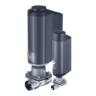
Electromotive diaphragm valve
Hide thumbs
Also See for 3323:
- Operating instructions manual (130 pages) ,
- Quick start manual (44 pages) ,
- Quick start manual (44 pages)

Related Manuals for Burkert 3323


Summary of Contents for Burkert 3323
- Page 1 Type 3323, 3324, 3325 AE3363, AE33 Electromotive diaphragm valve Operating instructions...
- Page 2 We reserve the right to make technical changes without notice. Technische Änderungen vorbehalten. Sous réserve de modifications techniques. Bürkert Werke GmbH & Co. KG, © 2016 – 2023 Operating Instructions 2309/04_EN-GB_00810538 / Original EN...
-
Page 3: Table Of Contents
Type 3323, 3324, 3325 Electromotive diaphragm valve ontent OPERATING INSTRUCTIONS ........................7 Symbols ............................7 1.2 Definition of terms ........................7 INTENDED USE ............................8 BASIC SAFETY INSTRUCTIONS ......................9 GENERAL NOTES..........................11 4.1 Contact address .........................11 4.2 Warranty .............................11 4.3 Information on the Internet ......................11 PRODUCT DESCRIPTION ........................12 5.1 General description ........................12 5.2 Properties ...........................12 5.3... - Page 4 Type 3323, 3324, 3325 8.3 Type label ...........................27 8.4 Labelling of forged steel valve body ..................28 8.5 Labelling of tube valve body (VP) ....................28 8.6 Operating conditions .........................29 8.7 General technical data .......................32 8.8 Electrical data ..........................33 8.9 Flow values for VS forged steel valve bodies ................35 8.10 Flow values for cast valve bodies and plastic valve bodies ............36 8.11 Flow values for tube valve bodies .....................37 INSTALLATION ............................38 9.1 Safety instructions for installation .....................38 9.2 Installation position of the diaphragm valves ................38 9.3 Installation of devices with threaded connection, flange connection, clamp connection or bonded connection ........................41...
- Page 5 Type 3323, 3324, 3325 12.1 Overview: availability of the operating elements ..............70 12.2 Display elements ..........................71 12.3 Operating elements ........................72 12.4 büS service interface .........................73 12.5 SIM card – acquire and save data (option) ..................74 12.6 User interface of the Bürkert Communicator PC software............... 75 12.7 Establish the connection between device and Bürkert Communicator ........76 BASIC FUNCTIONS ..........................77 13.1 Changing the operating state, AUTOMATIC, MANUAL ............77 13.2 Set safety position and effective direction ................78 ADVANCED FUNCTIONS ..........................79 14.1 X.TIME –...
- Page 6 Type 3323, 3324, 3325 büS ..............................104 19.1 Cabling of büS networks ......................104 19.2 Configuration of büS networks ....................104 MAINTENANCE ..........................105 20.1 Visual inspection ........................105 20.2 Replacing the diaphragm ......................106 20.3 Maintenance notifications .......................112 TROUBLESHOOTING .........................113 21.1 Notifications on device status “Out of specification” ............113 21.2 Error notifications ........................114 21.3 Notifications on device status “Function check” ..............116 CLEANING ............................117 22.1 Rinsing the valve body ......................117 ACCESSORIES, REPLACEMENT PARTS ..................118 23.1 Accessories ..........................118...
-
Page 7: Operating Instructions
Symbol for software interface texts. Definition of terms • The term “device” used in these instructions applies to the Type 3323, 3324, 3325 and AE3363 electro- motive diaphragm valve. • The abbreviation “Ex” used in these instructions stands for “potentially explosive”. -
Page 8: Intended Use
Type 3323, 3324, 3325 Intended use INTENDED USE Improper use of the Type 3323, 3324 and 3325 electromotive diaphragm valve may be dangerous to people, nearby equipment and the environment. The type 3323, 3324 and 3325 electromotive diaphragm valve is designed to control the flow of liquid and gaseous media. ▶ Standard devices must not be used in the potentially explosive area. They do not possess the separate Ex type label denoting the approval for use in potentially explosive environments. -
Page 9: Basic Safety Instructions
Type 3323, 3324, 3325 Basic safety instructions BASIC SAFETY INSTRUCTIONS This safety information does not take into account any contingencies or occurrences that may arise during installation, use and maintenance of the device. The operating company is responsible for the respect of the local safety regulations, including staff safety. - Page 10 Type 3323, 3324, 3325 Basic safety instructions ▶ In potentially explosive atmospheres, only use devices with a separate Ex type label. ▶ Only the media listed in Chapter “8 Technical data” should be fed into the medium ports. ▶ Do not make any internal or external changes to the device and do not subject it to mechanical stress.
-
Page 11: General Notes
A precondition for the warranty is that the device is used as intended in consideration of the specified ope- rating conditions. Information on the Internet Operating instructions and data sheets for Types 3323, 3324 and 3325 can be found on the Internet at: country.burkert.com English... -
Page 12: Product Description
PRODUCT DESCRIPTION General description The type 3323, 3324, and 3325 electromotive diaphragm valve is suitable for controlling the flow of liquid and gaseous media. These can be neutral, ultra-pure, sterile as well as contaminated, aggressive or abrasive media of high to low viscosity. -
Page 13: Options
Type 3323, 3324, 3325 Product description Options • Energy storage system (SAFEPOS energy-pack) for reaching safety position. The safety position that the valve is supposed to take in the event of a supply voltage failure is specified with the DIP switch. -
Page 14: Structure And Function
Structure and function STRUCTURE AND FUNCTION The electromotive diaphragm valve of Types 3323, 3324 and 3325 consists of an electromotively driven linear actuator, diaphragm and a diaphragm valve body. The control electronics and “SAFEPOS energy-pack” are housed in the side of the linear actuator. - Page 15 Type 3323, 3324, 3325 Structure and function Pressure compen- sation element/access Blind cover with status indi- to the mechanical cator and bayonet catch manual override SAFEPOS energy- pack (optional) Actuator cover Actuator housing Electrical connec- tions (circular plug-in Viewing window with position...
-
Page 16: Valve Position After Supply Voltage Failure
Type 3323, 3324, 3325 Structure and function 6.1.3 Tank bottom valve Valve body Diaphragm socket Actuator base Diaphragm Viewing window with position indicator Actuator housing Actuator cover Electrical connectors (circular plug-in connector or cable gland) Blind cover with status indicator and bayonet catch Fig. -
Page 17: Display Of The Device Status
Type 3323, 3324, 3325 Structure and function Display of the device status The device status is displayed on the LED light ring. Various LED modes may be configured to display the device’s status and valve position: • Valve mode • Valve mode + warnings (factory pre-set) •... - Page 18 Type 3323, 3324, 3325 Structure and function 6.4.3 NAMUR operation mode In NAMUR mode the LED light ring lights up in the colour specified for the device status as per NAMUR NE 107. If several device statuses exist simultaneously, the device status with the highest priority is displayed. The priority is based on the severity of the deviation from standard operation (red = failure = highest priority).
-
Page 19: Factory Settings
Type 3323, 3324, 3325 Structure and function 6.4.5 Notifications on device status Notifications on device statuses and errors are entered into the logbook. Chapter “20 Maintenance” con- tains the most common notifications and the measures that they require. Notifications on device status “Function check” The notifications are presented when operation is interrupted by work on the device. -
Page 20: Control Electronics
Type 3323, 3324, 3325 Control electronics CONTROL ELECTRONICS Function The actuator (stroke) position is controlled by the digital input. The position is specified either by en external signal (analogue) or via a fieldbus (digital). The position sensor records the current position of the electrical linear actuator and from this creates an end position signal via the digital outputs. - Page 21 Type 3323, 3324, 3325 Control electronics AG3 Variant Electromotive control Inputs Outputs valve 2 digital outputs Digital input 24 V PNP Supply Communication Fieldbus 24 V actuator supply büS/CANopen 24 V büS/CAN supply Remarks: Optional interfaces are shown with a dashed line büS service interface Fig.
-
Page 22: Energy Storage Safepos Energy-Pack (Option)
Type 3323, 3324, 3325 Control electronics 7.1.2 Functional diagram 2 signals for the end External Controller position signal positions Actual position Motor Gear Position sensor Valve (actuator) Fig. 7: Functional diagram Energy storage SAFEPOS energy-pack (option) The device can also be equipped with the energy storage system (SAFEPOS energy-pack). In the event of a supply voltage failure, the energy storage system supplies the actuator with the energy required to move the valve to the safety position. - Page 23 Type 3323, 3324, 3325 Control electronics ATTENTION! The energy storage system SAFEPOS energy-pack is a wearing part. The service life figures are appro- ximate values that cannot be guaranteed. 7.2.2 Notifications on the state of the SAFEPOS energy-pack The device issues a warning: the energy storage system capacity is greatly reduced. The energy storage system must be replaced soon.
- Page 24 Type 3323, 3324, 3325 Control electronics SAFEPOS energy-pack Safety screw (hexalobular-internal T10) Fig. 8: Removing SAFEPOS energy-pack Inserting new SAFEPOS energy-pack: → Remove the SAFEPOS energy-pack from the transport packaging. → Insert the SAFEPOS energy-pack into the two guide grooves on the side and push it in until it stops.
- Page 25 Type 3323, 3324, 3325 Control electronics 7.2.4 Replace SAFEPOS energy-pack (AG3) CAUTION! Risk of injury from electrical voltage. ▶ Turn off the supply voltage before removing the SAFEPOS energy-pack. ▶ Ensure that the SAFEPOS energy-pack is fully discharged. Wait until the LED ring is no longer lit and ensure...
- Page 26 Type 3323, 3324, 3325 Control electronics Removing SAFEPOS energy-pack: CAUTION! Risk of injury from electrical voltage. ▶ Ensure that the red LED to display the residual voltage has gone out before the components are touched. → Remove printed circuit board → Remove adapter cable. Fig. 11: Remove printed circuit board and adapter cable →...
-
Page 27: Technical Data
Type 3323, 3324, 3325 Technical data TECHNICAL DATA The following product-specific information is provided on the type label: • Voltage [V] (tolerance ± 10%) and current type • Diaphragm material and valve body material • Fieldbus standard • Flow capacity • Diaphragm size • Actuator size • Port connection •... -
Page 28: Labelling Of Forged Steel Valve Body
Type 3323, 3324, 3325 Technical data 8.3.1 UL additional label (example) Type AE33-SD Power Supply SELV / PELV only! LISTED Process control equipment E238179 Fig. 14: UL additional label (example) Labelling of forged steel valve body Labelling may vary depending on variant. -
Page 29: Operating Conditions
Type 3323, 3324, 3325 Technical data Operating conditions The product-specific information on the type label must be heeded when operating the device. WARNING! Functional failure when exceeding or falling below the permissible temperature range. ▶ Never expose the device to direct sunlight in outdoor areas. ▶ The permissible ambient temperature range must not be exceeded or undercut. Reduced sealing function if medium pressure too high. Because the diaphragm valve is closed against the medium flow, an excessive medium pressure may cause the valve to not close tightly. - Page 30 Type 3323, 3324, 3325 Technical data 8.6.2 Permitted medium temperature ATTENTION! Depending on the medium temperature the behaviour of the medium temperature in relation to the dia- phragm material may change. ▶ The specified medium temperatures only apply to medium that do not attack the diaphragm materials or cause it to swell up.
- Page 31 Type 3323, 3324, 3325 Technical data Diagram for nominal diameter values (DN) 15 to 40: Temperature [°C] Fig. 17: Diagram: dependent on medium temperature and medium pressure for plastic valve body 8.6.3 Temperature diagram for medium and environment The maximum permitted temperature for the environment and medium are dependent on one another. The permitted maximum temperatures of the device variants can be determined using the characteristics of the temperature diagram.
-
Page 32: General Technical Data
Type 3323, 3324, 3325 Technical data 140 150 Medium temperature [°C] Fig. 19: Temperature diagram AG3 Item Description Device without module Devices with SAFEPOS energy-pack* Devices with fieldbus gateway * The service life of the SAFEPOS energy-pack is dependent on the medium temperature and ambient temperature (see chapter “Electrical data”). -
Page 33: Electrical Data
Type 3323, 3324, 3325 Technical data Clamp connection as per: DIN 32676 B (ISO 4200) DIN 32676 A (DIN 11850 2) ASME BPE Flange connection, threaded socket connection and bond connection (connection sizes on request). Electrical connection: with connection terminal (only AG2) or circular plugs Installation position: depends on body variant. - Page 34 Type 3323, 3324, 3325 Technical data The operating current can be reduced by the following measures, if necessary 1. For devices with the SAFEPOS energy-pack: Setting the “Control if ready”, reduces the max. operating current by 1 A. Setting in the configuration areaPosition controller → Parameter → ENERGY-PACK →...
-
Page 35: Flow Values For Vs Forged Steel Valve Bodies
Type 3323, 3324, 3325 Technical data Flow values for VS forged steel valve bodies CV values for VS forged steel valve bodies CV value [m³/h] Diaphragm Sealing DN connection size material ASME EPDM 6 / 1/8" PTFE EPDM 8 / 1/4" PTFE EPDM 10 / 3/8" PTFE EPDM 15 / 1/2"... -
Page 36: Flow Values For Cast Valve Bodies And Plastic Valve Bodies
Type 3323, 3324, 3325 Technical data 8.10 Flow values for cast valve bodies and plastic valve bodies CV values for VG cast and plastic (PD, PP, PV) valve bodies CV value [m³/h] Sealing Diaphragm size DN connection Cast valve body VG (all Plastic valve body (all material standards) materials) EPDM 0.95 8 1/4" PTFE EPDM 15 / 1/2" PTFE EPDM 10.7 20 / 3/4"... -
Page 37: Flow Values For Tube Valve Bodies
Type 3323, 3324, 3325 Technical data 8.11 Flow values for tube valve bodies CV values for 3G tube valve bodies VP (IHU2) CV value [m³/h] Sealing Diaphragm size DN connection material ASME EPDM 8 / 1/4" PTFE EPDM 10 / 3/8" PTFE EPDM 15 / 1/2" PTFE EPDM 15 / 1/2" PTFE EPDM 20 / 3/4"... -
Page 38: Installation
Type 3323, 3324, 3325 Installation INSTALLATION Safety instructions for installation WARNING! Risk of injury due to improper assembly. ▶ Installation may be carried out by trained technicians only and with the appropriate tools. ▶ Secure the system to prevent unintentional activation. ▶ After installation, ensure that the process is restarted in a controlled manner. Observe the sequence. - Page 39 If the self-drainage angle is not specified on the valve body, please refer to the additional manual “Angle specifications for self-draining“ on our website. The installer and the operator are responsible for ensuring self-drainage. country.burkert.com. Type / Manuals / Additional manual “Angle information for self-drainage”. If you require clarification, contact your Bürkert sales department. 9.2.2...
- Page 40 Type 3323, 3324, 3325 Installation 9.2.3 Installation position for tank bottom body Preferably actuator facing downwards. Fig. 22: Installation position of Type 3325 English...
-
Page 41: Installation Of Devices With Threaded Connection, Flange Connection, Clamp Connection Or Bonded Connection
Type 3323, 3324, 3325 Installation Installation of devices with threaded connection, flange connection, clamp connection or bonded connection ATTENTION! Damage to the diaphragm. ▶ To prevent damage, the device must be in MANUAL operating state during installation. Devices in their factory default state already have their operating state set to MANUAL. - Page 42 Type 3323, 3324, 3325 Installation Holding device To protect the valve actuator from damage resulting from forces and vibrations, a holding device is recommended. This is available as an accessory. See chapter “23 Accessories, replacement parts”. Next steps: • Electrical installation, chapter “10” on page 54.
-
Page 43: Installation Of Devices With Welded Connections
Type 3323, 3324, 3325 Installation Installation of devices with welded connections ATTENTION! National regulations regarding welder qualifications and the performance of welding work must be observed. For devices with a tank bottom body, special measures must be observed when they are welded in. - Page 44 Type 3323, 3324, 3325 Installation 9.4.2 Required tool • Allen key, width across flats 3 mm. Required when no supply voltage is applied to the device in order to move the valve into the open position. • Open-end wrench 9.4.3 Welding 2-way valve body or T-valve body into pipeline Precondition: The actuator and diaphragm must be removed from the valve body.
- Page 45 Type 3323, 3324, 3325 Installation 9.4.4 Welding tank bottom body Precondition: The actuator and diaphragm must be removed from the valve body. DANGER! Risk of injury from high pressure. ▶ Before working on the system, switch off the pressure and vent or empty the lines. Recommendations: Observe sequence: 1. Note: Weld the tank bottom body to the container base before the container is assembled.
-
Page 46: Installing Actuator On Valve Body
Type 3323, 3324, 3325 Installation Next steps: • If the diaphragm is not mounted, mount it on the actuator, chapter .“9.5.3” on page 46 • Install the actuator onto the valve body and establish electrical connection, chapter “9.5.4” on page 48. - Page 47 Type 3323, 3324, 3325 Installation Compressor Insert Compressor with installed insert Fig. 23: Place insert into compressor → Screw diaphragm into compressor by hand. → Loosen by half a turn. → Align diaphragm. The mark tab of the diaphragm must protrude from the valve body at a right angle to the longitudinal axis of the pipeline (see “Fig.
- Page 48 Type 3323, 3324, 3325 Installation 9.5.4 Mount the actuator onto the valve body and establish electrical connection WARNING! Risk of injury from electric shock. Risk of crushing by mechanically powered parts. ▶ Switch off the supply voltage. ATTENTION! Damage to the diaphragm. ▶ To prevent damage, the device must be in MANUAL operating state during installation.
- Page 49 Type 3323, 3324, 3325 Installation Unlock blind cover CLOSE key OPEN key Fig. 25: Execute M. SERVICE → To unlock the blind cover, turn it counterclockwise and remove. → Hold down the OPEN and CLOSE keys together at the same time for 5 seconds.
-
Page 50: Rotating The Actuator
Type 3323, 3324, 3325 Installation Holding device To protect the valve actuator from damage resulting from forces and vibrations, a holding device is recommended. This is available as an accessory. See chapter “23 Accessories, replacement parts”. Next steps: • Execute TUNE function for position control, chapter “11.3” on page 66 (AG2) and “11.4” on page 67 (AG3). -
Page 51: Disassembling The Actuator
Type 3323, 3324, 3325 Installation Disassembling the actuator DANGER! Risk of injury from high pressure. ▶ Before working on the system or device, switch off the pressure and ventilate or empty the lines. WARNING! Risk of injury due to improper installation work. ▶ The actuator may be removed only by trained technicians and with the appropriate tools. - Page 52 Type 3323, 3324, 3325 Installation Actuator Diaphragm socket Nuts (4 units) Diaphragm Valve body Body screws (4 units) Fig. 27: Disassembly of the diaphragm using the 2-way body as an example → Remove the body screws. → Remove valve body.
-
Page 53: Holding Device
Type 3323, 3324, 3325 Installation Holding device The holding device protects the valve actuator and body from damage resulting from forces and vibrations. The holding device is available as an accessory. See chapter “23 Accessories, replacement parts”. 9.8.1 Install the holding device →... -
Page 54: Electrical Installation
Type 3323, 3324, 3325 Electrical installation ELECTRICAL INSTALLATION The electromotive diaphragm valve is available in 2 connection variants: • With a circular plug-in connector (multi-pin variant) • Cable gland with connection terminals (only AG2) Signal values Operating voltage: 24 V Digital input for position signal: 0...5 V = log “0”;... - Page 55 Type 3323, 3324, 3325 Electrical installation 10.1.2 Description of circular plug-in connectors X3 – Circular plug M12, 5-pin A-coded Operating voltage AG2 and büS/ CANopen X1 – Circular plug M12, 8-pin A-coded Input and output signals FE functional earth Fig. 29: Description of circular plug-in connectors AG3 variant X3 – Circular plug M12, 5-pin A-coded büS/CANopen X1 – Circular plug M12, 8-pin...
- Page 56 Type 3323, 3324, 3325 Electrical installation 10.1.3 X1 – Circular plug M12, 8-pin Input and output signals Wire colour* Assignment (from device perspective) Input signals from control centre (e.g. PLC) 0-5 V (log. 0) white Digital input + 10-30 V (log. 1) Output signals to control centre (e.g. PLC) only required with analogue output and/or digital output option yellow Digital output 1 24 V/0 V...
- Page 57 Type 3323, 3324, 3325 Electrical installation 10.1.5 X3 – Circular plug M12, 5-pin, büS/CANopen network AG3 For variants with fieldbus gateway, using this connection is optional for service büS. Wire colour with büS Assignment (from device perspective) network* CAN shield 24 V ± 10% max. residual ripple 10%...
-
Page 58: Electrical Connection Fieldbus Gateway
Type 3323, 3324, 3325 Electrical installation 10.2 Electrical connection fieldbus gateway The fieldbus gateway for Industrial Ethernet is connected using 4-pin M12 circular plug-in connectors. Female connector M12, 4-pin Pin Assignment Ethernet, Port 1 and 2 Transmit + Receive + Transmit –... -
Page 59: Electrical Installation With Cable Gland (Only Ag2)
Type 3323, 3324, 3325 Electrical installation 10.3 Electrical installation with cable gland (only AG2) WARNING! Risk of injury from improper installation. ▶ Installation may be carried out by authorised technicians only and with the appropriate tools. ▶ Observe general engineering standards & rules during installation. - Page 60 Type 3323, 3324, 3325 Electrical installation 2. Remove the LED and storage module: Removing actuator cover: Remove the LED and storage module: Fastening Actuator screws cover Fastening screws Metal housing of LED and storage module Fig. 35: Remove the LED and storage module and remove the actuator cover 3. Removing actuator cover:...
- Page 61 Type 3323, 3324, 3325 Electrical installation 10.3.2 Connecting the cable → Push the cable through the cable gland. ATTENTION! Take note for connection to spring-loaded terminals. ▶ Minimum length of wire ferrules: 8 mm ▶ Maximum cross-section of the wire ferrule: 1.5 mm (without collar), 0.75 mm (with collar).
- Page 62 Type 3323, 3324, 3325 Electrical installation 10.3.3 Terminal layout – input signal from control centre (e.g. PLC) Terminal Assignment (from device perspective) 0-5 V (log. 0) Digital input + 10-30 V (log. 1) Digital input, GND relates to GND operating voltage (GND terminal)
- Page 63 Type 3323, 3324, 3325 Electrical installation 10.3.5 Closing the actuator housing ATTENTION! The ingress of dirt or moisture may cause damage or malfunction. To preserve IP65 and IP67 degree of protection, ensure the following before closing the device: ▶ The seal in the actuator housing/actuator cover must be inserted and undamaged.
- Page 64 Type 3323, 3324, 3325 Electrical installation → Carefully press down the LED and storage module by hand. The end position is reached if the upper edge of the module is fully and evenly recessed in the actuator cover. ATTENTION! The plug connection will be damaged if the LED and storage module is not correctly inserted.
-
Page 65: Start-Up
Type 3323, 3324, 3325 Start-up START-UP WARNING! Risk of injury due to improper operation. Improper operation may result in injuries as well as damage to the device and the surrounding area. ▶ The operating personnel must know and understand the contents of the operating instructions. ▶ The safety instructions must be followed and the device used only as intended. -
Page 66: Adjustment Of Position Control On Ag2
Type 3323, 3324, 3325 Start-up 11.3 Adjustment of position control on AG2 The position control is preset and adjusted at the factory for devices with a fitted valve body when delivered. When executing the function M.Q0.TUNE the position control is adjusted at the actual stroke of the propor- tional valve in use and the required closing force is determined. -
Page 67: Adjustment Of Position Control On Ag3
Type 3323, 3324, 3325 Start-up 11.3.2 Adjust with buttons in the device The two buttons for approaching the seal closure point and for triggering M.Q0.TUNE are located under the blind cover. CLOSE key OPEN key Unlock blind cover Fig. 40: Adjustment of the mechanical end position with keys in device →... - Page 68 Type 3323, 3324, 3325 Start-up ATTENTION! Only run TUNE if necessary. It is only necessary to adjust the position control again if the actuator has been dismantled and/or the diaphragm or the valve body has been replaced, or if the valve is loose. With the M.Q0.TUNE function, the tight closing point and the tight closing force can be adapted to the current operating conditions.
-
Page 69: Set Automatic Operating State
Type 3323, 3324, 3325 Start-up 11.4.2 Adjustment of position control on PC Adjustments are performed on a PC via the büS service interface using the “Bürkert Communicator” PC software. It requires the USB-büS-Interface available as an accessory. To avoid damage to the device, only use the power supply unit supplied in the USB-büS-interface set. -
Page 70: Operation
Type 3323, 3324, 3325 Operation OPERATION WARNING! Risk of injury from improper operation. Improper operation may result in injuries as well as damage to the device and its surroundings. ▶ The operating personnel must know and understand the contents of the operating instructions. ▶ The safety instructions must be followed and the device used only as intended. -
Page 71: Display Elements
Type 3323, 3324, 3325 Operation 12.2 Display elements Description of the display elements: LED illuminated ring 4 different, adjustable LED modes Mechanical Open valve position indicator Close valve Fig. 43: Display elements 12.2.1 LED illuminated ring The transparent LED illuminated ring that transmits the light of the LEDs to the outside is fitted to the blind cover. -
Page 72: Operating Elements
Type 3323, 3324, 3325 Operation 12.3 Operating elements Presentation of the operating elements: SIM card DIP switch büS service interface CLOSE key OPEN key Mechanical manual override Fig. 44: Operating elements 12.3.1 DIP switch Settings Switch 1: Enable or disable safety position, see chapter “13.2” on page 78. -
Page 73: Büs Service Interface
Type 3323, 3324, 3325 Operation 12.4 büS service interface The büS service interface can be used for quick service. • Configuration of the device, e.g. the base setting for start-up with the PC software Bürkert Communicator. It requires the USB-büS-Interface set available as an accessory. -
Page 74: Sim Card - Acquire And Save Data (Option)
Type 3323, 3324, 3325 Operation 12.5 SIM card – acquire and save data (option) The optional SIM card can be used to store device-specific values and user settings and transfer them to another device. The configuration client (for BüS devices) is disabled when the SIM card is inserted. -
Page 75: User Interface Of The Bürkert Communicator Pc Software
Type 3323, 3324, 3325 Operation 12.6 User interface of the Bürkert Communicator PC software Configuration area view: Navigation area Menu bar Add interface (connect with büS stick) COMMUNICATOR File Device Edit View Options Tools Help Positioner Home page Parameters Diagnostics Maintenance Desktop... -
Page 76: Establish The Connection Between Device And Bürkert Communicator
Type 3323, 3324, 3325 Operation View of the application area: Current user level COMMUNICATOR File Edit View Options Tools Device Help 0029671400000001 E_Process_Valve 3323 Home page Positioner Desktop 73.7% Graph büS Inputs/outputs 0029671400000001 E_Process_Valve 3323 Positioner Inputs/outputs General settings Zoom 100% Overview: Configuration areas of the... -
Page 77: Basic Functions
Type 3323, 3324, 3325 Basic functions BASIC FUNCTIONS The basic functions are set using the DIP switch position. DIP switch Basic function Enable or disable safety position DIP switch Set safety position and effective direction (NC and NO) Not assigned Switches between AUTOMATIC and MANUAL mode. -
Page 78: Set Safety Position And Effective Direction
Type 3323, 3324, 3325 Basic functions 13.2 Set safety position and effective direction The effective direction and safety position are set using DIP switches 1 and 2. DIP switch 2 DIP switch 1 Switch position Set-point value Effective Switch position Safety position (safety position (0-5 V) -
Page 79: Advanced Functions
Type 3323, 3324, 3325 Advanced functions ADVANCED FUNCTIONS 14.1 X.TIME – limitation of control speed This auxiliary function can be used to set the opening and closing times for the entire stroke, and thus limit the control speeds. When performing M.Q0.TUNE function, the minimum opening and closing time are entered for the entire stroke for Open and Close. - Page 80 Type 3323, 3324, 3325 Advanced functions How to configure the control time limit: → Select X.TIME in the “Parameter” detailed view. → Select Opening time. → Enter and confirm the lower limit value. → Select Closing time. → Enter and confirm the upper limit value. You have enabled and configured the control time limit.
-
Page 81: X.limit - Mechanical Stroke Range Limit
Type 3323, 3324, 3325 Advanced functions 14.2 X.LIMIT – mechanical stroke range limit This auxiliary function limits the (physical) stroke to defined per cent values (minimum and maximum). The stroke range of the limited stroke is thereby set to 100%. -
Page 82: Set Led Operation Mode
Type 3323, 3324, 3325 Advanced functions → Select in the detailed view “Parameter”. X.LIMIT → Select Maximum. → Enter and confirm the upper limit value. You have enabled and configured the mechanical stroke limit. 14.3 Set LED operation mode Configuration using the Bürkert Communicator software on PC: The Bürkert Communicator PC software can be downloaded free of charge from the Bürkert website. -
Page 83: Setting The Colours For Indicating Valve Position
Type 3323, 3324, 3325 Advanced functions 14.4 Setting the colours for indicating valve position The colours on the LED light ring that indicate the valve positions can be set individually. Configuration using the Bürkert Communicator software on PC: The Bürkert Communicator PC software can be downloaded free of charge from the Bürkert website. -
Page 84: Manual Override Of Valve
Type 3323, 3324, 3325 Manual override of valve MANUAL OVERRIDE OF VALVE The actuation of the valve can be manually overridden by electrical or mechanical means. Electrical manual override is usually used to manually open and close the valve. The mechanical manual override must only be used to open and close the valve if there is a power failure. The manual override may be only be used while in a de-energised state. -
Page 85: Actuating The Valve Mechanically
Type 3323, 3324, 3325 Manual override of valve 15.2 Actuating the valve mechanically If there is no supply voltage, e.g. during installation or in the event of a power failure, the valve can be opened or closed using the mechanical manual override. - Page 86 Type 3323, 3324, 3325 Manual override of valve Unscrew the pressure compen- sation element Turn Close Open Mechanical press and turn manual override for changing the valve position Fig. 54: Mechanical manual override AG3 Remove the blind cover: Devices with ATEX approval or IECEx approval are secured with a magnetic lock. The removal of the cover is described in the supplementary instructions for the electromotive control valves with ATEX approval and IECEx approval.
- Page 87 Type 3323, 3324, 3325 Manual override of valve → Once the desired valve position is achieved, remove the Allen key. The mechanical manual override mechanism will disengage automatically. Close blind cover: → Mount blind cover and turn clockwise until the 2 marks (one vertical line on the blind cover and on the actuator) are vertically aligned.
- Page 88 Type 3323, 3324, 3325 Manual override of valve Align and position fieldbus gateway. Close fieldbus gateway. Fieldbus gateway Closed position: Connection cable Actuator cover Icon for closed Mark Icon for opened Attach fieldbus gateway. Fastening screw Fig. 57: Mounting fieldbus gateway: →...
-
Page 89: Operating Structure And Factory Setting
Type 3323, 3324, 3325 Operating structure and factory setting OPERATING STRUCTURE AND FACTORY SETTING The factory default settings are depicted in blue in the operating structure to the right of the menu. Examples: Factory-enabled or selected menu options Factory-disabled or unselected menu options sec, ... - Page 90 Type 3323, 3324, 3325 Operating structure and factory setting 1) Only available in devices with SAFEPOS energy-pack (option). Positioner MAINTENANCE CALIBRATION M.CLEAN Fig. 59: Operating structure – 1-b, positioner maintenance Positioner DIAGNOSTICS SYSTEM.VALUES Operation time Travel accumulator Direction change Device temperature...
- Page 91 Type 3323, 3324, 3325 Operating structure and factory setting Fig. 60: Operating structure – 1-c, positioner diagnostics Positioner DIAGNOSTICS USER.DIAGNOSIS ADD.DIAGNOSE SERVICE.TIME TRAVEL.ACCU CYCLE.COUNTER POS.MONITOR HISTOGRAM.POS HISTOGRAM.SPAN SERVICE.TIME Operation time Interval Next message TRAVEL.ACCU Travel accumulator Interval Next message CYCLE.COUNTER...
- Page 92 Type 3323, 3324, 3325 Operating structure and factory setting Inputs/outputs PARAMETERS Digital CMD.source büS CANopen Fieldbus ADDITIONAL IOs DIGITAL OUT 1 FUNCTION Position limit DIGITAL OUT 2 Device state Manual mode Safepos Position Limit Device State Maintenance Out of specification...
- Page 93 Type 3323, 3324, 3325 Operating structure and factory setting General settings PARAMETERS Mode Status LED NAMUR operation mode Valve mode Valve mode + warnings LED off Yellow Valve open Green Valve closed Green Valve in between büS Displayed name Location...
- Page 94 Type 3323, 3324, 3325 Operating structure and factory setting General settings PARAMETERS Diagnostics PDO Configuration PDO 1 PDO 2 PDO 3 Multiplexed PDO Reset to default values Fig. 64: Operating structure – 3-b, configuration area “General settings” General settings MAINTENANCE...
- Page 95 Type 3323, 3324, 3325 Operating structure and factory setting General settings DIAGNOSTICS Device status Operating duration Device temperature Power supply Min./max. Values Max temperature Transferable memory status Min. temperature Max. supply voltage Min. supply voltage Receive errors büS status Receive errors max.
-
Page 96: Industrial Ethernet
Type 3323, 3324, 3325 Industrial Ethernet INDUSTRIAL ETHERNET To allow connection to an Ethernet network, the electromotive control valve with integrated fieldbus gateway is optionally available. Supported fieldbus protocols: Ethernet/IP, PROFINET, Modbus TCP. 17.1 Fieldbus gateway description Fieldbus gateway Fieldbus connector M12 (2-port Ethernet switch) Fig. -
Page 97: Technical Data Industrial Ethernet
Type 3323, 3324, 3325 Industrial Ethernet LED state Fault description/cause Action Link/Act Active Rapid flashing: Connection with overriding protocol layer EtherNet/IP has been established. Data are (green) being transmitted. Slow flashing: there is no connection to the pro- tocol layer. This is normally the case for approx. 20 seconds after restarting. -
Page 98: Projecting Via Fieldbus
The start-up files required for the respective project planning software and their description are available on the Internet. Download at: www.burkert.com / Type 3323 / Downloads “Software” / Device Description Files Please refer to the documentation of your project design software for instructions regarding the installation of the start-up files. - Page 99 Type 3323, 3324, 3325 Industrial Ethernet How to switch to detailed view: → For setting with Bürkert Communicator, select Industrial Communication in the navigation area. → When using the display for the configuration, switch to CONFIGURATION on the home screen and select Industrial Communication. You are now in the “Parameter” detailed view.
-
Page 100: Web Server
Type 3323, 3324, 3325 Industrial Ethernet 17.4 Web server The configuration of the Ethernet participant, required to connect to the network, can be run via a web server. 17.4.1 Connecting to the web server → Only for PROFINET: Assign IP addresses and DNS-compatible name with a suitable start-up tool for PROFINET attachments. - Page 101 Type 3323, 3324, 3325 Industrial Ethernet 17.4.2 Access to the web server Bürkert 3320 S/N: 99 Industrial Communication Protocol PROFINET Communication Wait for establishing communication status DNS compatible name MAC address 00:50:C2:C7:E0:01 Static IP address 192.168.0.100 Network mask 255.255.255.0 Default gateway 192.168.0.1 Temporary IP 192.168.0.100...
- Page 102 Type 3323, 3324, 3325 Industrial Ethernet Configuration of multiple devices: On delivery, all devices have the same IP address (192.168.0.100 or 0.0.0.0 for PROFINET). So that the device can be identified for configuration, only 1 unconfigured device may be on the network. ▶ Successively connect the devices (Ethernet participants) to the network individually and configure them.
- Page 103 Type 3323, 3324, 3325 Industrial Ethernet Configuration: → Enter the device name and IP address for the Ethernet participant. The device name assigned here is used later during project planning (e.g. under STEP 7). → Confirm with Commit changes. Conduct a power reset of the Ethernet participant to incorporate the changed parameters.
-
Page 104: Canopen
The eds file and the associated description are available on the Internet. Download at: www.burkert.com / Type 3323 / Downloads “Software” / Device Description Files Please refer to the documentation of your project design software for instructions regarding the installation of the start-up files. -
Page 105: Maintenance
Type 3323, 3324, 3325 Maintenance MAINTENANCE WARNING! Risk of injury due to improper maintenance work. ▶ Maintenance may be carried out only by trained specialist technicians and with the appropriate tools. ▶ Secure the system against unintentional activation. ▶ Ensure a controlled restart after maintenance is completed. -
Page 106: Replacing The Diaphragm
Type 3323, 3324, 3325 Maintenance 20.2 Replacing the diaphragm DANGER! Risk of injury from high pressure. ▶ Before working on the system or device, switch off the pressure and ventilate or empty the lines. WARNING! Risk of injury due to improper installation work. ▶ The diaphragm may be replaced only by trained technicians and with the appropriate tools. - Page 107 Type 3323, 3324, 3325 Maintenance 20.2.3 Removing actuator from the valve body Prerequisites: MANUAL operating state, valve position 100% open, supply voltage switched off. WARNING! Risk of injury from electric shock. Risk of crushing by mechanically powered parts. ▶ Switch off the supply voltage. ▶ For devices with SAFEPOS energy-pack: completely remove the SAFEPOS energy-pack. Wait until the LED ring is no longer lit and ensure that the LED status indicator is not in “LED off”...
- Page 108 Type 3323, 3324, 3325 Maintenance 20.2.4 Replacing the diaphragm → Unbutton or unscrew the old diaphragm (see “Tab. 30: Fixture types for diaphragms”). If the diaphragm has a bayonet catch: → Detach the diaphragm by turning it 90° and remove it.
- Page 109 Type 3323, 3324, 3325 Maintenance Fixture of buttoned diaphragm: → Attach buttons of diaphragm in compressor. → Align diaphragm. The mark tab of the diaphragm must protrude from the valve body at a right angle to the longitudinal axis of the pipeline (see “Fig. 74”).
- Page 110 Type 3323, 3324, 3325 Maintenance 20.2.5 Mount the actuator onto the valve body and establish electrical connection WARNING! Risk of injury from electric shock. Risk of crushing by mechanically powered parts. ▶ Switch off the supply voltage. ATTENTION! Damage to the diaphragm. ▶ To prevent damage, the device must be in MANUAL operating state during installation.
- Page 111 Type 3323, 3324, 3325 Maintenance Unlock blind cover CLOSE key OPEN key Fig. 75: Execute M.SERVICE → To unlock the blind cover, turn it counterclockwise and remove. → Hold down the OPEN and CLOSE keys together at the same time for 5 seconds.
-
Page 112: Maintenance Notifications
Type 3323, 3324, 3325 Maintenance Next steps: • Execute TUNE function for position control, chapter “11.3” on page 66 (AG2) and “11.4” on page 67 (AG3). ATTENTION! Damage to the diaphragm. ▶ To prevent damage, execute the function M.Q0.TUNE first after establishing the electrical connection. -
Page 113: Troubleshooting
Type 3323, 3324, 3325 Troubleshooting TROUBLESHOOTING 21.1 Notifications on device status “Out of specification” Notifications on device status “Out of specification” are displayed in the following LED operation modes: • Valve mode + warnings (factory pre-set). The LED light ring alternatingly flashes yellow and the colour indicating the valve position. -
Page 114: Error Notifications
Type 3323, 3324, 3325 Troubleshooting 21.2 Error notifications Device error notifications are displayed as follows: • Valve mode The LED light ring alternatingly flashes red and the colour indicating the valve position. • Valve mode + warnings (factory pre-set). The LED light ring alternatingly flashes red and the colour indicating the valve position. - Page 115 Type 3323, 3324, 3325 Troubleshooting Message Description Device behaviour Action Internal error: reverbation Signal failure of the Error notification. Contact Bürkert service. sensor signal failure. position sensor. Actuator is moving to safety position. MANUAL operating state not possible. Internal error: …...
-
Page 116: Notifications On Device Status "Function Check
Type 3323, 3324, 3325 Troubleshooting 21.3 Notifications on device status “Function check” Notifications on device status “Function check” are displayed in the following LED operation modes: • Valve mode + warnings (factory pre-set). The LED light ring alternatingly flashes orange and the colour indicating the valve position. -
Page 117: Cleaning
Type 3323, 3324, 3325 Cleaning CLEANING ATTENTION! The use of alkaline cleaning agents is not permitted for cleaning the surface of the device. 22.1 Rinsing the valve body The device has a M.CLEAN function for residue-cleaning of parts in contact with media. -
Page 118: Accessories, Replacement Parts
Type 3323, 3324, 3325 Accessories, replacement parts ACCESSORIES, REPLACEMENT PARTS 23.1 Accessories CAUTION! Risk of injury and/or damage due to incorrect parts. Incorrect accessories and unsuitable spare parts may cause injuries and damage to the device and the area around it ▶ Use only original accessories and original spare parts from Bürkert. -
Page 119: Communication Software
Type 3323, 3324, 3325 Accessories, replacement parts 23.2 Communication software The PC software Bürkert Communicator is designed for communication with Bürkert devices. A detailed description of the installation and operation of the PC software can be found in the asso- ciated operating instructions. -
Page 120: Disassembly
Type 3323, 3324, 3325 Disassembly DISASSEMBLY DANGER! Risk of injury due to high pressure and escaping medium. If the device is pressurised while being disassembled, there is a risk of injury due to sudden depressuri- sation and medium discharge. ▶ Turn off the pressure before dismantling the device. Vent or empty the lines. -
Page 121: Packaging, Transport
Type 3323, 3324, 3325 Packaging, transport PACKAGING, TRANSPORT CAUTION! Risk of injury due to a heavy device. During transportation or installation work, the device may fall down and cause injuries. ▶ Transport, install and remove heavy device with the aid of a second person only. ▶ Use suitable tools. - Page 122 www.burkert.com...
Need help?
Do you have a question about the 3323 and is the answer not in the manual?
Questions and answers