Burkert 3363 Quick Start Manual
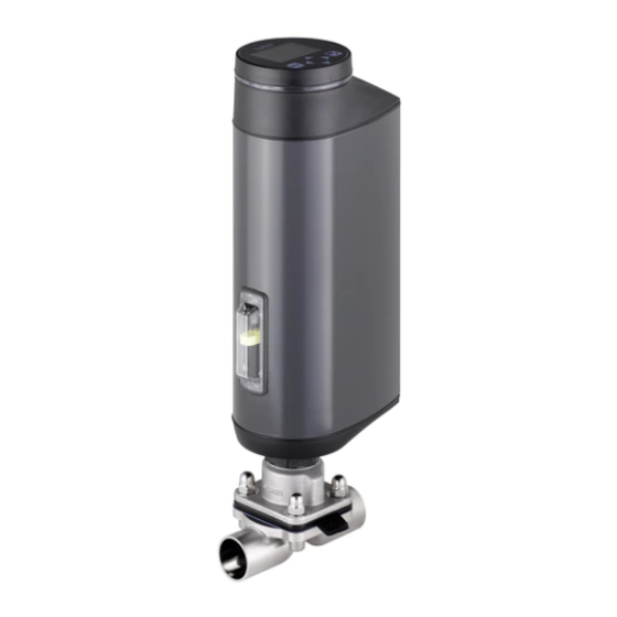
Electromotive diaphragm control valve
Hide thumbs
Also See for 3363:
- Operating instructions manual (182 pages) ,
- Quick start manual (200 pages) ,
- Replacement instructions manual (6 pages)

Related Manuals for Burkert 3363


Summary of Contents for Burkert 3363
- Page 1 Type 3363, 3364, 3365 AE3363, AE3364, AE3365 Electromotive diaphragm control valve Quickstart English...
- Page 2 We reserve the right to make technical changes without notice. Technische Änderungen vorbehalten. Sous réserve de modifications techniques. © Bürkert Werke GmbH & Co. KG, 2016 – 2018 Operating Instructions 1810/03_EU-ML_00810536 / Original DE...
-
Page 3: Table Of Contents
Type 3363, 3364, 3365 Contents Installing diaphragm and actuator ........20 THE QUICKSTART .............. 4 Rotating the actuator ..............23 Definition of the term "device" ..........4 Holding device .................24 Symbols ..................5 8 ELECTRICAL INSTALLATION ............... 25 2 INTENDED USE .....................5 Electrical installation with circular plug-in connector ..25... -
Page 4: The Quickstart
12.2 Actuating valve mechanically ..........50 regarding the use of the device. A detailed description can be found in the operating instructions for Type 3363, 3364 and 3365. 13 FIELDBUS GATEWAY ................51 Keep the quickstart in a location which is easily accessible to every 13.1 Technical data ................51... -
Page 5: Symbols
Type 3363, 3364, 3365 Intendeduse Symbols INTENDED USE The following symbols are used in these instructions. Non-authorized use of the electromotive diaphragm control valve Type 3363, 3364 and 3365 may be a hazard to people, DANGER! nearby equipment and the environment. Warns of an immediate danger. The electromotive diaphragm control valve Type 3363, ▶ Failure to observe the warning will result in fatal or serious injuries. 3364 and 3365 is designed to control the flow of liquid and gaseous media. WARNING! ▶ Standard devices must not be used in the potentially explosive area. -
Page 6: Basic Safety Instructions
Type 3363, 3364, 3365 Basicsafetyinstructions BASIC SAFETY INSTRUCTIONS ▶ If the valve position is relevant as regards safety in the event of a power failure: Use only those devices which have the These safety instructions do not consider any contingencies or incidents SAFEPOS energy-pack (optional energy pack). -
Page 7: General Information
Information on the Internet • Do not touch electronic components while the supply voltage is switched on. Operating instructions and data sheets for Types 3363, 3364 and 3365 can be found on the Internet at: www.burkert.com english... -
Page 8: Structure And Function
Do not position indicator unscrew! * F actory setting; colors can be changed (see software description with reference to Type 3363 at www.burkert.com). FE functional ground Actuator base Tab. 1: Display of device state in valve mode w/ warnings... -
Page 9: Technical Data
• Actuator size • Line connector • Maximum permitted medium pressure Conformity The electromotive diaphragm control valves Type 3363, 3364 and 3365 are compliant with EU directives as stated in the EU Declaration of Conformity. Standards The applied standards, which are used to demonstrate compliance... -
Page 10: Labeling Of The Bodies
Type 3363, 3364, 3365 Technicaldata 6.4.1 UL aAdditional type label for UL Company logo approval (example) Material Heat 1.4435 316L(VP) Type AE3363 XXXXXXXX Nominal pressure PN16 / CWP150 Power Supply SELV / PELV only! LISTED Orifice Process Control Equipment connection and... - Page 11 Type 3363, 3364, 3365 Technicaldata 6.6.1 Permitted temperature ranges WARNING! The permitted medium and ambient temperature ranges Reduced sealing function if medium pressure too high. depend on various factors: As the diaphragm control valve is closed against the medium flow, Medium temperature: depends on the material of the valve the medium pressure may become too high and prevent the valve body and diaphragm materials.
- Page 12 Type 3363, 3364, 3365 Technicaldata Permitted medium temperature for diaphragm materials Permitted medium temperature for valve bodies made of plastic The permitted medium temperature for valve bodies made of plastic Permitted medium temperature range Diaphragm depends on the medium pressure. material minimal maximal Steam sterilisation DN 15 - 40 EPDM (AB), PTFE/ -10 °C +130 °C +140 °C/60 min.
-
Page 13: General Technical Data
Type 3363, 3364, 3365 Technicaldata General technical data Materials Actuator: PPS and aluminum powder-coated Valve body Metal: Investment casting (VG), forged steel (VS), tubular-formed body (VP), Plastic: PP, PVC and PVDF Body connection: CF-8 / 1.4308 Spindle seal: Seal material:... - Page 14 Type 3363, 3364, 3365 Technicaldata 6.7.1 Electrical data Supply current transmitter: Max. 150 mA, available only for devices with process controller function. DANGER! Standby consumption [W]**: min. 2 W, max. 5 W Electric shock. Average consumption [W]** Protection class III is only guaranteed when using a SELV Electronics without actuator standard consumption: typically 3 W power supply unit or PELV power supply unit.
- Page 15 Type 3363, 3364, 3365 Technicaldata ATTENTION! PTFE for each diaphragm size Consider voltage drop in supply line. For example, a cable cross-section of 0.34 mm must not exceed a line length of 8 meters for a copper cable. Analog inputs: ( galvanically isolated from the supply voltage and analog output) Input data for set- point value signal Input resistance 60 Ω...
-
Page 16: Installation Of The Valve
Type 3363, 3364, 3365 Installationofthevalve Analog output INSTALLATION OF THE VALVE (optional) WARNING! Max. current: 10 mA (for voltage output 0...5/10 V) 0...800 Ω (for current output 0/4...20 mA) Burden (load): Risk of injury from improper assembly. ▶ The assembly may be carried out only by trained technicians Digital outputs and with the appropriate tools. -
Page 17: Installation Position Of The Diaphragm Control Valves
Type 3363, 3364, 3365 Installationofthevalve Installation position of the 7.1.2 Installation position of T-body diaphragm control valves Installation position: The installation position of the diaphragm control valve varies For supply of a medium: For removal of a medium: depending on the valve body. -
Page 18: Installation Of Devices With Socket Connection, Flanged Connection, Clamp Connection Or Bond Connection
Type 3363, 3364, 3365 Installationofthevalve → Installation of devices with socket Connect the device electrically. The position of the connections can be aligned by rotating connection, flanged connection, the actuator through 360°. For a description see chapter “7.5 clamp connection or bond Rotating the actuator”. - Page 19 Type 3363, 3364, 3365 Installationofthevalve 7.3.2 Welding tank bottom body Delivery condition for devices with welded connection The devices are delivered in a disassembled state. Observe sequence: Operating state: MANUAL. Position of the actuator: Valve open. 1. Weld the tank bottom body onto the base of the tank before installing the tank.
-
Page 20: Installing Diaphragm And Actuator
Type 3363, 3364, 3365 Installationofthevalve Installing diaphragm and actuator Observe the applicable laws and regulations of the respective country with regard to the qualification of Depending on the size of the diaphragm, there are different fastening welders and the execution of welding work. types for the diaphragm. Diaphragm EPDM / FKM / 1. Welding tank bottom body onto the tank: PTFE size laminated PTFE ATTENTION! Diaphragm pressed in... - Page 21 Type 3363, 3364, 3365 Installationofthevalve → 7.4.1 Mounting actuator on the valve body Hand-tighten the diaphragm into the pressure piece. → and making the electrical connections Loosen by half a rotation. → ATTENTION! Align diaphragm. The identification tab on the diaphragm must protrude out of the Damage to the diaphragm.
- Page 22 Type 3363, 3364, 3365 Installationofthevalve Running M.SERVICE using buttons in the device: Running M.SERVICE on the device display: The 2 buttons for running the M.SERVICE are located under the Display operation: Key functions dummy cover. select, activate confirm back Devices with ATEX approval or IECEx approval. The devices are secured with a special cover. The removal of To run the M.SERVICE function, you must change to the detailed...
-
Page 23: Rotating The Actuator
Type 3363, 3364, 3365 Installationofthevalve 7.4.2 Following installation WARNING! → Following installation, make the required basic settings and Risk of injury due to non-observance of the tightening torque. adjustments for the electromotive diaphragm control valve. For a description see chapter “9 Start-up”. Non-observance of the tightening torque is hazardous as the device may be damaged. -
Page 24: Holding Device
Type 3363, 3364, 3365 Installationofthevalve Holding device → Attach holding device to the hexagon of the actuator as shown in the diagram. NOTE! Ensure that the actuator is rotated into the correct position beforehand. → Fix the holding device in place using suitable means. Hexagon of the actuator Fig. 16: Rotating the actuator The actuator cannot be rotated if devices are fitted with a holding device. -
Page 25: Electrical Installation
Type 3363, 3364, 3365 Electricalinstallation ELECTRICAL INSTALLATION ATTENTION! The electromotive diaphragm control valve is available with one of 2 To ensure electromagnetic compatibility (EMC) the functional ground different connections: must be grounded with a short cable (max. 1m). The functional •... - Page 26 Type 3363, 3364, 3365 Electricalinstallation 8.1.2 Description of the circular plug-in 8.1.3 X1 – M12 circular plug, 8-pole connectors Pin Wire (From point of view of the device) Assignment color* X3 – circular plug M12, 5-pole Input signals from the control centre (e.g. PLC) operating voltage Set-point value + (0/4...20 mA or 0...5/10 V) galvanically...
- Page 27 Type 3363, 3364, 3365 Electricalinstallation 8.1.4 X2 – M12 socket, 5-pole, input signals On the Signal Wire External process actual value (for process Assignment device type* color circuit side controller function only) Frequency 1 brown not used On the Signal Wire External...
-
Page 28: Electrical Installation With Cable Gland
Type 3363, 3364, 3365 Electricalinstallation 8.1.5 X3 – M12 circular plug, 4-pole or 5-pole, Electrical installation with cable operating voltage gland Wire color Assignment 8.2.1 Safety instructions (From point of view of without büS network with büS WARNING! the device) 4-pole connection* network Risk of injury from improper installation. CAN shield ▶... - Page 29 Type 3363, 3364, 3365 Electricalinstallation 8.2.2 Access to the connection terminals Device version with display module: → Disconnect the connection cable from the HMI interface. To access the terminals, open the device as described below. 1. Remove display module or dummy cover: 2. Removing LED and storage module: → Remove the 2 fastening screws (hexagon head key, width across NOTE! flats 3 mm).
- Page 30 Type 3363, 3364, 3365 Electricalinstallation ATTENTION! Connection terminals Damage or malfunction due to ingress of dirt and moisture. To comply with the degree of protection IP65: ▶ Close all unused cable glands with dummy plugs. ▶ Tighten the union nuts on the cable glands. Tightening torque depends on cable size or dummy plug approx. 1.5 Nm (1.1 lbf ft).
- Page 31 Type 3363, 3364, 3365 Electricalinstallation 8.2.4 Terminal assignment – input signal from * E lectrical installation of büS network: the control center (e.g. PLC) Terminals 1, 2 and 3 (CAN interface) are for the connection of the büS network. Terminal Assignment (From point of view of the device)
- Page 32 Type 3363, 3364, 3365 Electricalinstallation 8.2.7 Terminal assignment – process actual On the Signal value input (for process controller Terminal Assignment device External circuit type* side function only) Frequency not used On the Signal - externally PV1: clock input + Clock+ Terminal Assignment...
- Page 33 Type 3363, 3364, 3365 Electricalinstallation 8.2.8 Closing the device Dummy cover ATTENTION! or display module Damage or malfunction due to ingress of dirt and moisture. Before closing the device, comply with the degree of protection IP65 by ensuring: LED and storage module ▶ that the seal is inserted in the actuator housing/actuator cover and is not damaged.
-
Page 34: Start-Up
Type 3363, 3364, 3365 Start-up START-UP • Adjust the position control using 2 capacitive buttons in the device (M.Q0.TUNE function) Possible only for devices without display module. WARNING! Basic settings Risk of injury from improper operation. A start-up wizard, which runs gradually through the base Improper operation may result in injuries as well as damage to the setting, is available for the Bürkert-Communicator... -
Page 35: Setting Safety Position
The fine adjustment of the process parameters is described in the 2. Select physical unit for process Percentage software description with reference to Type 3363, 3364, 3365. control 3. Parameterize process values Setting safety position a) Select standard signal for Signal type analog: 4...20 mA... -
Page 36: Adjust The Position Control - Running M.q0.Tune
Type 3363, 3364, 3365 Start-up Adjust the position control – running The following safety positions can be selected: M.Q0.TUNE Close Valve tightly closed. When the M.Q0.TUNE function is running, the position control is adjusted to the physical stroke of the actuator used and the required Open Valve open. - Page 37 The position control can be automatically adjusted for devices remove from the actuator housing. with process controller function. For a description see oper- ating instructions for Type 3363. Devices with ATEX approval or IECEx approval. The devices are secured with a special cover. The removal of...
- Page 38 Type 3363, 3364, 3365 Start-up To run the M.Q0.TUNE function, you must change to the detailed 2. Temperature!” view maintenance for position controller. → Confirm. Changing from View 1 to the detailed view: → Using the arrow key, approach the sealing point. → When setting with Bürkert-Communicator in the navigation area, →...
-
Page 39: Set Standard Signal For Set-Point Position
Type 3363, 3364, 3365 Start-up Set standard signal for set-point Select physical unit for process position control Setting option: Setting option: Using the PC software Bürkert-Communicator or on the Using the PC software Bürkert-Communicator or on the display of the device (option) -
Page 40: Parameterize Process Values
Type 3363, 3364, 3365 Start-up Parameterize process values Scaling the process set-point value: → Select SP .scale. Setting option: → Using the PC software Bürkert-Communicator or on the Input minimum and maximum. display of the device (option) You have parameterized the process set-point value. Display operation: Key functions 9.7.2 Select and scale standard signal for... -
Page 41: Scaling Process Control
Type 3363, 3364, 3365 Start-up Scaling process control Setting dead band of the process control The scaling of the process control affects the following functions: • Dead band of the process control Setting option: Using the PC software Bürkert-Communicator or on the •... -
Page 42: Set Up Process Control - Run P.lin
Type 3363, 3364, 3365 Start-up 9.10 Set up process control – run P.LIN, 9.10.2 Adjustment to process control (P.TUNE) P.TUNE Running the P.TUNE function: → Setting option: Using the PC software Bürkert-Communi- Select P.TUNE. cator or on the display of the device (option) The following text appears: “Do you really want to start the P.Tune?”... -
Page 43: Operation
Type 3363, 3364, 3365 Operation OPERATION 10.1.1 LED illuminated ring The transparent LED illuminated ring, which transmits the light of the WARNING! LEDs outwards, is attached to the dummy cover or display module. The device status is indicated by a lit, flashing or rapidly flashing Danger due to improper operation. -
Page 44: Control Elements
Type 3363, 3364, 3365 Operation 10.2 Control elements 10.2.2 OPEN button and CLOSE button Electrical manual Open valve: Press OPEN button control: Close valve: Press CLOSE button SIM card When closing the valve: Carefully close the valve at low force to DIP switches prevent damaging the diaphragm. -
Page 45: Display Operation (Option)
Type 3363, 3364, 3365 Displayoperation(option) DISPLAY OPERATION (OPTION) 11.2 Description of the keys The device is operated and set via a display with a touch-screen. Functions 11.1 User interface Press briefly: Back Digital Back key Jump back to View 1... -
Page 46: Display Views
Type 3363, 3364, 3365 Displayoperation(option) 11.3 Display views 11.4 Description of the symbols You go from the start screen to the following views: Symbols for user rights • Configuration view, using the left navigation key . Symbol Description • View 2...4 created by the user, using the right navigation The setting is write-protected and can be changed key . - Page 47 Type 3363, 3364, 3365 Displayoperation(option) Symbols for indicating the device status according to NAMUR Symbols for indicating the operating states NE 107 Priority Symbol Description If several device statuses exist simultaneously, the device status with the highest priority is displayed. Device has stopped control mode due to a serious error. The valve remains in its...
-
Page 48: Manual Actuation Of The Valve
Type 3363, 3364, 3365 Manualactuationofthevalve MANUAL ACTUATION OF THE Switch to MANUAL operating state: VALVE → To switch to MANUAL operating state, briefly press the Menu The diaphragm control valve can be manually actuated in 2 ways: key. electrically or mechanically. The HAND symbol can be seen on the information bar. - Page 49 Type 3363, 3364, 3365 Manualactuationofthevalve 12.1.2 Devices without display module Switch to MANUAL operating state: → Set DIP switch 4 to ON. The device is now in MANUAL operating The 2 buttons for opening and closing the valve are located under the dummy cover.
-
Page 50: Actuating Valve Mechanically
Type 3363, 3364, 3365 Manualactuationofthevalve → 12.2 Actuating valve mechanically To release the display module or the dummy cover, rotate counter-clockwise by 90° and remove from the actuator housing. When the supply voltage is not applied, e.g. during installation or in the event of a power failure, the valve can be opened or closed with On the display module pay attention to the connection cable. -
Page 51: Fieldbus Gateway
Type 3363, 3364, 3365 Fieldbusgateway FIELDBUS GATEWAY Mechanical Manual Open valve EtherNet/IP, PROFINET and Modbus TCP Control Display module Fieldbus Fieldbus con- gateway nection M12 (2 Port Ethernet Switch)Switch) Press and rotate Close valve Fig. 35: Fieldbus gateway with display module Fig. -
Page 52: Electrical Connection
Type 3363, 3364, 3365 Fieldbusgateway 13.2 Electrical connection 13.3 Access to the büS Service interface The EtherNet/IP is connected with a circular plug-in connector M12, The büS Service interface is located inside the fieldbus gateway. 4-pole. To access, open the cover using a screwdriver. -
Page 53: Maintenance, Troubleshooting
Type 3363, 3364, 3365 Maintenance,Troubleshooting MAINTENANCE, 14.2 Replacing the diaphragm TROUBLESHOOTING WARNING! The following maintenance work is required for the diaphragm control valve. Risk of injury due to escape of medium and pressure release • After the first steam sterilisation or when required It is dangerous to remove a device which is under pressure due to →... - Page 54 Type 3363, 3364, 3365 Maintenance,Troubleshooting → 14.2.2 Removing the diaphragm Remove body screws. → ATTENTION! Remove valve body. → Detach or unscrew diaphragm (see „Tab. 22: Fastening types for Damage to the diaphragm diaphragms“). ▶ To prevent damage, the device must be in MANUAL operating Diaphragm with bayonet catch: →...
-
Page 55: Accessories
773254 (M12 to büS service interface micro USB) Tab. 23: Components USB büS interface set Information on Type 3363, 3364 and 3365 can be found on the Internet at www.burkert.com • Additional accessories (in the operating instructions) english... -
Page 56: Packaging, Transport, Storage
Type 3363, 3364, 3365 Packaging,Transport,Storage PACKAGING, TRANSPORT, STORAGE ATTENTION! Transport damage. Inadequately protected devices may be damaged during transportation. • Protect the device against moisture and dirt in shock-resistant packaging during transportation. Incorrect storage may damage the device. Devices with diaphragm: • Storage temperature –20 to +70 °C. (The higher the storage temperatures, the quicker the elastomers age.) - Page 57 www.burkert.com...
Need help?
Do you have a question about the 3363 and is the answer not in the manual?
Questions and answers