Burkert 3360 Manuals
Manuals and User Guides for Burkert 3360. We have 11 Burkert 3360 manuals available for free PDF download: Quick Start Manual, Operating Instructions Manual, Service Manual, Replacement Instructions Manual, Manual
Burkert 3360 Quick Start Manual (175 pages)
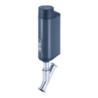
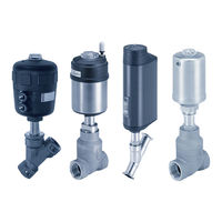
Electromotive control valve
Brand: Burkert
|
Category: Control Unit
|
Size: 7 MB
Table of Contents
Advertisement

Burkert 3360 Quick Start Manual (158 pages)
Electromotive control valve
Brand: Burkert
|
Category: Control Unit
|
Size: 5 MB
Table of Contents

Burkert 3360 Operating Instructions Manual (160 pages)
Electromotive control valve
Brand: Burkert
|
Category: Control Unit
|
Size: 7 MB
Table of Contents
Advertisement

Burkert 3360 Operating Instructions Manual (165 pages)
Electromotive control valve
Brand: Burkert
|
Category: Control Unit
|
Size: 9 MB
Table of Contents

Burkert 3360 Service Manual (57 pages)
Electromotive
Brand: Burkert
|
Category: Control Unit
|
Size: 2 MB
Table of Contents

Burkert 3360 Quick Start Manual (53 pages)
Electromotive control valve
Brand: Burkert
|
Category: Control Unit
|
Size: 1 MB
Table of Contents

Burkert 3360 Quick Start Manual (51 pages)
Electromotive control valve
Brand: Burkert
|
Category: Control Unit
|
Size: 1 MB
Table of Contents

Burkert 3360 Service Manual (34 pages)
Electromotive
Brand: Burkert
|
Category: Control Unit
|
Size: 6 MB
Table of Contents
Burkert 3360 Replacement Instructions Manual (17 pages)
Process valves
Brand: Burkert
|
Category: Control Unit
|
Size: 1 MB
Table of Contents

Burkert 3360 Manual (6 pages)
Electromotive control valve
Brand: Burkert
|
Category: Control Unit
|
Size: 0 MB
Table of Contents

Burkert 3360 Replacement Instructions Manual (6 pages)
Changing the SAFEPOS energy-pack
Brand: Burkert
|
Category: Control Unit
|
Size: 1 MB