Burkert 3361 Operating Instructions Manual
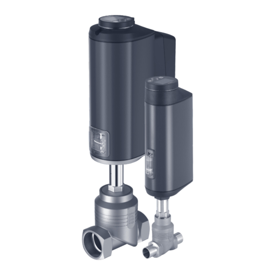
Electromotive control valve
Hide thumbs
Also See for 3361:
- Quick start manual (175 pages) ,
- Operating instructions manual (160 pages) ,
- Service manual (57 pages)

Related Manuals for Burkert 3361


Summary of Contents for Burkert 3361
- Page 1 Type 3360, 3361, AE3360, AE3361, AE33 Electromotive control valve Operating instructions...
- Page 2 We reserve the right to make technical changes without notice. Technische Änderungen vorbehalten. Sous réserve de modifications techniques. © Bürkert Werke GmbH & Co. KG, 2016–2024 Operating Instructions 2403/07_ENen_00810490 / Original DE...
-
Page 3: Table Of Contents
Types 3360 and 3361 Electromotive control valve nhalt OPERATING INSTRUCTIONS ................. 8 Symbols ............................8 1.2 Definition of terms ........................9 INTENDED USE ............................10 BASIC SAFETY INSTRUCTIONS ......................11 GENERAL NOTES..........................13 4.1 Contact address .........................13 4.2 Warranty .............................13 4.3 Information on the Internet ......................13 PRODUCT DESCRIPTION ........................14 5.1 General description ........................14 5.2... - Page 4 Types 3360 and 3361 8.2 Approvals ...........................35 8.3 Type label ...........................35 8.4 Operating conditions .........................36 8.5 General technical data .......................39 8.6 Electrical data ..........................40 8.7 Flow rate values and flow rate characteristics for angle seat control valve (Type 3360)..43 8.8 Flow rate values and flow rate characteristics for globe control valve (Type 3361) ....47 INSTALLING THE VALVE ........................50 9.1 Safety instructions ........................50 9.2 Installation of devices with threaded connection, flange connection or clamp connection ..50 9.3 Installation of devices with welded connections ..............52 9.4 Disassembly of the actuator from the valve body ..............54 9.5...
- Page 5 Types 3360 and 3361 11.11 Set dead band for process control ...................82 11.12 Setting up process control and executing P.LIN, P.TUNE ............83 11.13 Set AUTOMATIC operating state ....................85 OPERATION ............................86 12.1 Overview: availability of the operating elements ..............86 12.2 Display elements ..........................87 12.3 Operating elements ........................89 12.4 büS service interface .........................90 12.5 SIM card – acquire and save data (option) ..................91 DISPLAY OPERATION (OPTION) ......................92 13.1 User interface ..........................92 13.2 Description of buttons .......................92 13.3 Display views ..........................93 13.4 Description of symbols ......................97...
- Page 6 Types 3360 and 3361 17.1 Operating structure of the configuration area ................125 17.2 Context menu for operation on display ..................143 INDUSTRIAL ETHERNET ........................145 18.1 Fieldbus gateway description ....................145 18.2 Technical data Industrial Ethernet ...................147 18.3 Projecting via fieldbus ......................148 18.4 Web server ..........................150 CANopen ............................153 19.1 Projecting via fieldbus ......................153 19.2 CANopen network configuration .....................153 büS ..............................154 20.1 Cabling of büS networks ......................154 20.2 Configuration of büS networks ....................154 MAINTENANCE ..........................155...
- Page 7 Types 3360 and 3361 PACKAGING AND TRANSPORT ......................163 STORAGE ............................163 DISPOSAL ............................163 english...
-
Page 8: Operating Instructions
Types 3360 and 3361 Operating instructions OPERATING INSTRUCTIONS The operating instructions describe the entire life cycle of the device. Keep these instructions in an easily accessible location for every user. The instructions must be available to each new owner of the device. -
Page 9: Definition Of Terms
• Device: The term “Device” used in these instructions applies to the types described in these instructions: Type 3360, electromotive angle seat control valve Type 3361, electromotive globe control valve • AG2: Actuator size 2 with a nominal force of 1300 or 2500 N for seat size 3–50 AG3: Actuator size 3 with a nominal force of 7700 or 10000 N for seat size 40–100... -
Page 10: Intended Use
Types 3360 and 3361 Intended use INTENDED USE Improper use of the electromotive Type 3360 and 3361 control valve may be dangerous for people, nearby equipment and the environment. The electromotive control valve is designed to control the flow of liquid and gaseous media. ▶ Standard devices must not be used in the potentially explosive area. They do not possess the separate “Ex” type label denoting the approval for use in potentially explosive environments. -
Page 11: Basic Safety Instructions
Types 3360 and 3361 Basic safety instructions BASIC SAFETY INSTRUCTIONS These safety instructions do not take into account any unforeseen circumstances and events which occur during installation, operation and maintenance. The operator is responsible for observing the location-specific safety regulations, also with reference to personnel. - Page 12 Types 3360 and 3361 Basic safety instructions General hazardous situations. To prevent injury, ensure that: ▶ In potentially explosive environments the device must only be used in accordance with the specifica- tions on the separate type label. ▶ The additional information and safety instructions relating to potentially explosive atmospheres enclosed with the device or the separate operating instructions relating to potentially explosive atmospheres must be heeded when using the device.
-
Page 13: General Notes
A precondition for the warranty is that the device is used as intended and that the specified usage conditions are taken into account. Information on the Internet Operating instructions and data sheets for Types 3360 and 3361 can be found on the Internet at: country.burkert.com english... -
Page 14: Product Description
PRODUCT DESCRIPTION General description The electromotive control valve Type 3360 and 3361 is suitable for controlling the flow of liquid and gaseous media. This may be neutral gas, water, alcohol, oil, fuel, hydraulic fluid, salt solution, caustic soda, organic solvent or vapour. -
Page 15: Variants
Types 3360 and 3361 Product description 5.2.1 Special characteristics of the 2-way globe control valve (Type 3361): • Simple and quick replacement of the screwed-in valve seat. • Large expansion space above the valve seat that prevents body erosion caused by cavitation. - Page 16 1300 2500 1300, 1300, 1 1/2 1300 2500 2500 1300, 1300, 1300, 2500 2500 2500 Table 3: Globe control valve variants, Type 3361 AG2 Globe control valve Type 3361 AG3: Available actuator size in nominal force [N] DN connection Seat size valve (valve body) [DN] [NPS] 1 1/2 7700 7700 7700 10000 10000 10000 2 1/2...
- Page 17 Types 3360 and 3361 Product description 5.3.2 Options • Energy storage system (SAFEPOS energy-pack) for reaching safety position. The safety position that the valve is supposed to take in the event of a supply voltage failure is specified in the SAFEPOS menu.
-
Page 18: Structure And Function
Flow direction below seat, flow direction Fluidic connections: • The threaded socket connection, welded connection or clamp connection are available for all valve bodies. • The valve body with flange connection is also available for globe control valve Type 3361. english... -
Page 19: Representation - Structure Of The Electromotive Control Valve Ag2
Pressure component element indicator Do not unscrew! FE Functional earth Actuator base Relief bore Body connection (with wrench flat) Digits for indicating Globe valve body the flow direction Port connection Fig. 3: Assembly, electromotive globe control valve Type 3361 AG2 english... -
Page 20: Representation - Structure Of The Electromotive Control Valve Ag3
Types 3360 and 3361 Structure and function Representation – Structure of the electromotive control valve AG3 Pressure compensation element/access to the mechanical manual override Blind cover or display with SAFEPOS energy-pack status indicator and bayonet (optional) catch Only for devices with... -
Page 21: Safety Position
Types 3360 and 3361 Structure and function Valve position for devices with the SAFEPOS energy-pack energy storage: The valve assumes the safety position defined in the SAFEPOS menu. For a description of the SAFEPOS energy-pack energy storage system, see chapter “7.3 Energy storage SAFEPOS energy-pack (option)“ on page 31... -
Page 22: Display Of The Device Status
Notifications on device statuses “Out of specification”, “Maintenance required” and “Function check” are not displayed in the valve mode. The factory-set colours for displaying the valve positions “open” and “closed” can be switched. The described can be found in the software description for Types 3360, 3361 on our homepage country. burkert.com Displays in valve mode: If device status “Normal”: Continuously lit in the colour of the valve position. - Page 23 Types 3360 and 3361 Structure and function 6.5.3 NAMUR operation mode In NAMUR mode the LED light ring lights up in the colour specified for the device status as per NAMUR NE 107. If several device statuses exist simultaneously, the device status with the highest priority is displayed. The priority is based on the severity of the deviation from standard operation (red = failure = highest priority).
-
Page 24: Factory Settings
Types 3360 and 3361 Structure and function Notifications on device status “Function check” The notifications are presented when closed-loop control mode is interrupted by work on the device. Notifications on device status “Function check” MANUAL operating state active X.TUNE active P.TUNE active P.LIN active Process simulation active Signal generator active Table 8: Notifications on device status “Function check”... -
Page 25: Control Electronics
Types 3360 and 3361 Control electronics CONTROL ELECTRONICS • Variants Types 3360, 3361 with position control function Types 3360, 3361 with process control function (optional) • Position sensor Contact-free, high-resolution and wear-free. • Microprocessor-controlled electronics assembly For signal processing, closed-loop control and motor control. - Page 26 Types 3360 and 3361 Control electronics AG3 Variant Electromotive control Inputs Outputs valve Analogue feedback Input for set-point 4–20 mA position or process set- 0–10 V point value 4–20 mA 0–20 mA 0–10 V 0–5 V Remarks: Optional interfaces are...
-
Page 27: Functional Diagram Of The Electromotive Control Valve
Types 3360 and 3361 Control electronics Functional diagram of the electromotive control valve The black parts of the image describe the position control function. The additional elements for the process control function (optional) are depicted in blue. Types 3360 and 3361 Process set-point... -
Page 28: Functionality Of The Control Electronics
Types 3360 and 3361 Control electronics Functionality of the control electronics The additionally implemented PID controller can, except for the position control, also be used to conduct a process control (e.g. level, pressure, flow rate, temperature) for purposes of cascade control. - Page 29 Types 3360 and 3361 Control electronics 7.2.1 Schematic presentation of the position control Analogue: 4–20 mA, 0–20 mA, 0–10 V, 0–5 V Fieldbus gateway büS/CANopen X.LIMIT Manual X.CONTROL CMD* DIR.CMD SPLTRNG CHARACT CUTOFF X.TIME Fig. 9: Schematic presentation of the position control...
- Page 30 Types 3360 and 3361 Control electronics Measured Description variables Actual position Set-point Position controller function: Selection of the source for the input signal of the set-point position in the menu → → position Inputs/outputs CMD → CMD.source. Process controller function: The set-point position is specified by the process controller.
-
Page 31: Energy Storage Safepos Energy-Pack (Option)
Types 3360 and 3361 Control electronics Energy storage SAFEPOS energy-pack (option) The device can also be equipped with the energy storage system (SAFEPOS energy-pack). In the event of a supply voltage failure, the energy storage system supplies the actuator with the energy required to move the valve to the safety position. - Page 32 Types 3360 and 3361 Control electronics Devices with ATEX approval or IECEx approval are secured with a magnetic lock. The removal of the cover is described in the supplementary instructions for the electromotive control valves with ATEX approval and IECEx approval. 1. Blind cover 2. LED & storage module 3. Actuator cover The process for removing these parts is described in detail in chapter “10.3.2 Access to connection ter-...
- Page 33 Types 3360 and 3361 Control electronics Guide groove Guide groove Fig. 12: Inserting SAFEPOS energy-pack → Apply the safety screw (hexalobular-internal screw T10). → Connect supply voltage. 7.3.4 Replace SAFEPOS energy-pack (AG3) CAUTION! Risk of injury due to electrical voltage. ▶ Turn off the supply voltage before removing the SAFEPOS energy-pack.
- Page 34 Types 3360 and 3361 Control electronics Removing SAFEPOS energy-pack: CAUTION! Risk of injury due to electrical voltage. ▶ Ensure that the red LED to display the residual voltage has gone out before the components are touched. → Remove printed circuit board. → Remove adapter cable. Fig. 14: Remove printed circuit board and adapter cable →...
-
Page 35: Technical Data
Types 3360 and 3361 Technical data TECHNICAL DATA The following product-specific information is provided on the type label: • Voltage [V] (tolerance ± 10%) and type of current • Seal material • Fieldbus standard • Flow capacity • Actuator size • Maximum permitted operating pressure • Flow direction • Temperature specifications Standards and directives... -
Page 36: Operating Conditions
Types 3360 and 3361 Technical data 8.3.1 UL additional label (example) Type AE33-RA Power Supply SELV/PELV only! LISTED Process control equipment E238179 Fig. 17: UL additional label (example) Operating conditions Restrictions on technical data/operating conditions are possible for device variants with approvals or conformities. Observe the data sheet and nameplate of the respective device.. WARNING! Loss of function if operated below or above permitted temperature range. ▶ Never expose the device to direct sunlight in outdoor areas. - Page 37 Types 3360 and 3361 Technical data 8.4.1 Permitted temperature ranges Minimum temperatures Environment: -25 °C Medium: -10 °C (-40 °C on request) Maximum temperatures Environment: depends on the medium temperature, see subsequent temperature diagram. Medium: depends on the ambient temperature; see temperature diagram below, as well as usage limits of the valve (derating operating pressure).
- Page 38 Types 3360 and 3361 Technical data 220 230 Medium temperature [°C] Fig. 19: Temperature diagram AG3 Description Device without module Devices with SAFEPOS energy-pack* Devices with display module with/without SAFEPOS energy-pack* Devices with fieldbus gateway with/without display module with/without SAFEPOS energy-pack* * The service life of the SAFEPOS energy-pack is dependent on the medium temperature and ambient temperature (see chapter “Electrical data”).
-
Page 39: General Technical Data
Welded connection as per EN ISO 1127 (ISO 4200), DIN 11850 series 2 Clamp connection as per ISO 2852, DIN 32676, ASME BPE, BS 4825 Additionally for Type 3361 globe valve: Flange connection as per DIN 2634, ANSI B16.5 class 150, JIS 10K... -
Page 40: Electrical Data
Types 3360 and 3361 Technical data Electrical data WARNING! Electrical shock. Protection class III is only guaranteed when using an SELV or PELV power supply unit. Protection class 3 in accordance with DIN EN 61140 Electrical connections Devices with position controller function:... - Page 41 Types 3360 and 3361 Technical data The operating current can be reduced by the following measures, if necessary 1. For devices with the SAFEPOS energy-pack energy storage: Configuring the “Control if ready” reduces the max. operating current. → → →...
- Page 42 Types 3360 and 3361 Technical data ( electrically isolated from the supply voltage and analogue output) Analogue inputs: Input data for set-point value signal 0/4...20 mA: Input resistance <70 Ω Resolution 12 bit 0...5/10 V: Input resistance 22 kΩ Resolution 12-bit, resolution relates to 0–10 V Input data for actual value signal (optional) 4...20 mA:...
-
Page 43: Flow Rate Values And Flow Rate Characteristics For Angle Seat Control Valve (Type 3360)
Types 3360 and 3361 Technical data Flow rate values and flow rate characteristics for angle seat control valve (Type 3360) The flow rate values and resulting characteristic depend on the valve seat size. 8.7.1 Flow rate values and flow rate characteristic for seat size 15 Flow values Flow characteristic Flow coefficient Stroke [%] 0.16 0.17... - Page 44 Types 3360 and 3361 Technical data 8.7.3 Flow rate values and flow rate characteristic for seat size 25 Flow values Flow characteristic Flow coefficient Stroke [%] 0.34 0.36 0.62 11.5 13.0 14.2 15.4 Stroke [%] 16.0 Table 18: Angle seat control valve, flow rate values and flow rate characteristic for seat size 25 8.7.4...
- Page 45 Types 3360 and 3361 Technical data 8.7.5 Flow rate values and flow rate characteristic for seat size 40 Flow values Flow characteristic Flow coefficient Stroke [%] 0.48 0.66 14.0 20.0 24.5 28.0 32.0 34.5 Stroke [%] 36.0 Table 20: Angle seat control valve, flow rate values and flow rate characteristic for seat size 40 8.7.6...
- Page 46 Types 3360 and 3361 Technical data 8.7.7 Flow rate values and flow rate characteristic for seat size 65 Flow rate values Flow characteristic Flow coefficient Stroke [%] 20.0 35.0 48.0 Stroke [%] Table 22: Angle seat control valve, flow rate values and flow rate characteristic for seat size 65 english...
-
Page 47: Flow Rate Values And Flow Rate Characteristics For Globe Control Valve (Type 3361)
Types 3360 and 3361 Technical data Flow rate values and flow rate characteristics for globe control valve (Type 3361) 8.8.1 Flow rate characteristics The globe control valve exhibits various characteristics depending on the valve seat size. • Parabolic cone of equal per cent for valves with seat size 6–50 •... - Page 48 Types 3360 and 3361 Technical data 8.8.2 Flow rate values values DN connection values (valve body) Seat size valve [NPS] 1 1/4 17.8 1 1/2 13.6 24.5 2 1/2 25.5 39.5 Table 23: values, globe control valves Kv values DN connection Seat size Kv values [m (valve body) valve Stroke [%] [NPS] 0.003 0.007 0.015 0.025 0.037 0.052 0.065 0.078 0.090 0.10...
- Page 49 Types 3360 and 3361 Technical data DN connection Seat size Kv values [m (valve body) valve Stroke [%] [NPS] 1 1/2 0.40 0.50 0.75 10.7 13.6 0.48 0.60 0.85 11.0 15.0 20.0 0.60 0.70 13.8 18.2 24.0 0.48 0.60 0.90 11.6 16.0 21.0 0.60 0.70 1.00 14.0...
-
Page 50: Installing The Valve
Types 3360 and 3361 Installing the valve INSTALLING THE VALVE Safety instructions WARNING! Risk of injury due to improper installation. ▶ Installation may be carried out by trained technicians only with the appropriate tools. ▶ Secure the system against unintentional activation. ▶ After installation, ensure that the process is restarted in a controlled manner. Observe the sequence! 1. - Page 51 Types 3360 and 3361 Installing the valve 9.2.2 Mounting conditions arbitrary, ideally with actuator facing upwards. Installation position: Flow direction: indicated on the type label with an arrow and the digits 1 and 2. The 1 and 2 are also on the valve body for identification.
-
Page 52: Installation Of Devices With Welded Connections
Types 3360 and 3361 Installing the valve Installation of devices with welded connections NOTE! Damage to valve body, valve seat seal or diaphragm. ▶ To avoid damage, the valve should only be mounted in the opened valve position and in the MANUAL operating state. Devices in their factory default state already have their operating state set to MANUAL. - Page 53 Types 3360 and 3361 Installing the valve Filter: r equired for devices with approval as per EN 161. According to EN 161 “Automatic shut-off valves for gas burners and gas appliances”, a dirt trap, which prevents the penetration of a 1 mm test pin, must be installed upstream of the valve in the pipeline.
-
Page 54: Disassembly Of The Actuator From The Valve Body
Types 3360 and 3361 Installing the valve Disassembly of the actuator from the valve body DANGER! Risk of injury from high pressure. ▶ Before working on the system or device, switch off the pressure and vent or empty the lines. WARNING! Risk of injury due to improper installation work. ▶ The actuator may be removed only by trained technicians and with the appropriate tools. - Page 55 Types 3360 and 3361 Installing the valve Mechanical position indicator Valve position open Actuator Body connection Valve body Fig. 21: Actuator disassembly (with angle seat control valve as an example) → Clamp valve body into a holding device. → Place on the body connection with a suitable open-end wrench.
-
Page 56: Installing Actuator On Valve Body
Types 3360 and 3361 Installing the valve Installing actuator on valve body Prerequisites: MANUAL operating state, valve position at least 1/3 open, supply voltage switched off. → Before installing the actuator, check whether the seal for the valve body is present and undamaged. → Replace seal. Angle seat valve Globe valve Seal Seal Fig. - Page 57 Types 3360 and 3361 Installing the valve → Position the external thread of the valve body on the internal thread of the body connection. → Place on the body connection with a suitable open-end wrench. Do not use any tools for unscrewing, which could damage the body connection.
-
Page 58: Rotating The Actuator
Types 3360 and 3361 Installing the valve Rotating the actuator The position of the ports can be changed by turning the actuator through 360°. NOTE! Damage to the valve seat seal and valve seat contour when valve closed. If the valve is closed when the actuator is turned, the valve seat seal and the valve seat contour can be damaged. -
Page 59: Holding Device
Types 3360 and 3361 Installing the valve Holding device The holding device protects the valve actuator from damage resulting from forces and vibrations. The holding device is available as an accessory in 2 sizes. See chapter “24 Accessories, Wearing parts“ on page 161. -
Page 60: Electrical Installation
(max. 1 m). Functional earth must have a cross-section of at least 1.5 mm Use of set-point input 4–20 mA If several Type 3360 or 3361 devices are connected in series and the electrical power supply for a device in this connected series fails, the input of the failed device becomes highly resistive. - Page 61 Types 3360 and 3361 Electrical installation 10.1.2 Description of circular plug-in connectors AG2 and AG3 AG2 variant X3 – Circular plug M12, 5-pin A-coded Operating voltage AG2 and büS/ CANopen X1 – Circular plug M12, 8-pin Input and output signals X2 – M12 circular socket, 5-pin Input signals process actual value FE Functional earth Fig. 26:...
- Page 62 Types 3360 and 3361 Electrical installation Circular plug-in Analogue Fieldbus büS/ Analogue Fieldbus büS/ connector gateway CANopen gateway CANopen Optional for devices with process control function Table 27: Use of circular plug-in connector AG2/AG3 → Connect the device in accordance with the tables.
- Page 63 Types 3360 and 3361 Electrical installation 10.1.4 X2 – M12 circular socket, 5-pin, A-coded input signals process actual value (only with process control function) Signal Wire Assignment Device end External circuit type* colour 4–20 mA brown +24 V supply transmitter – internally Transmitter white...
- Page 64 Types 3360 and 3361 Electrical installation 10.1.5 X3 – Circular plug M12, 5-pin A-coded, operating voltage AG2 and büS/CANopen network Electrical installation with or without büS-network: In order to be able to use the büS network (CAN interface), a 5-pin circular plug and a shielded 5-wire cable must be used.
-
Page 65: Electrical Connection Fieldbus Gateway
Types 3360 and 3361 Electrical installation 10.1.7 X4 – Circular plug M12, L-coded, 5-pin, actuator supply AG3 Wire colour* Assignment brown 24 V ±10%, max. residual ripple 10% white Do not connect blue black Do not connect grey FE connected to housing * The specified wire colours relate to the 5-pin M12 connection cable, which is available as an accessory with ID No. -
Page 66: Electrical Installation With Cable Gland (Only Ag2)
▶ Following installation, ensure a controlled restart. Use of set-point input 4–20 mA If several Type 3360 or 3361 devices are connected in series and the electrical power supply for a device in this connected series fails, the input of the failed device becomes highly resistive. - Page 67 Types 3360 and 3361 Electrical installation → To unlock, turn the display module or the blind cover counterclockwise and remove. NOTE! For devices with display module, take note of the connection cable to the HMI interface. → For devices with display module, disconnect the connection cable from the HMI interface.
- Page 68 Types 3360 and 3361 Electrical installation 10.3.3 Connecting the cable → Push the cable through the cable gland. NOTE! Take note for connection to spring-loaded terminals. ▶ Minimum length of wire ferrules: 8 mm ▶ Maximum cross-section of the wire ferrule: 1.5 mm (without collar), 0.75 mm (with collar) →...
- Page 69 Types 3360 and 3361 Electrical installation 10.3.4 Terminal layout – input signal from control centre (e.g. PLC) Clip Assignment Set-point value + (0/4–20 mA or 0–5/10 V) for operating voltage electrically isolated Set-point value – 0...5 V (log. 0) Digital input + 10...30 V (log.
- Page 70 Types 3360 and 3361 Electrical installation 10.3.7 Terminal layout – process actual value input (only with process control function) Signal Clip Assignment Device end External circuit type* 4...20 mA +24 V supply transmitter – internally PV1: not used Transmitter supplied (identical to GND operating voltage)
- Page 71 Types 3360 and 3361 Electrical installation 10.3.8 Close device NOTE! The ingress of dirt or moisture may cause damage or malfunction. To preserve IP65 and IP67 protection, ensure the following before closing the device: ▶ The seal in the actuator housing/actuator cover must be inserted and undamaged. ▶ The seal surfaces must be clean and dry.
- Page 72 Types 3360 and 3361 Electrical installation 2. Mount LED and storage module: Fastening screws Upper edge of LED and storage module (end position lower than upper edge of actuator cover) Mechanical manual override Fig. 36: Mount LED and storage module: → Place the LED and storage module onto the actuator cover.
-
Page 73: Start-Up
Types 3360 and 3361 Start-up START-UP 11.1 Safety instructions WARNING! Risk of injury due to improper operation. Improper operation may result in injuries as well as damage to the device and the surrounding area. ▶ The operating personnel must know and understand the contents of the operating instructions. - Page 74 Types 3360 and 3361 Start-up 11.4.1 Base settings for position control Before delivery, the base settings for the position control have already been input by the manufacturer. See diagrams below. Type of base setting (observe sequence) Factory default setting Set safety position Close/open (dependent on device variant)
-
Page 75: Set Safety Position
Types 3360 and 3361 Start-up ** The P.TUNE function supports process control set-up by independently optimising process parameters. The process of fine-tuning process parameters is described in the Type 3360, 3361 software description. 11.5 Set safety position Setting option: Using the Bürkert Communicator software or the display of the device (optional). -
Page 76: Adjustment Of Position Controller - Execute X.tune
Types 3360 and 3361 Start-up 11.6 Adjustment of position controller – execute X.TUNE When executing the X.TUNE function, the position control is adjusted at the physical stroke of the actuator in use. Devices come with the X.TUNE function performed by the manufacturer. NOTE! Only perform X.TUNE if required! The X.TUNE function only has to be executed again if the actuator has been dismantled or the valve body has been replaced. - Page 77 Types 3360 and 3361 Start-up 11.6.2 Adjustment of position control on PC or device display Settings are created on the PC using the büS service interface and the Bürkert Communicator software. It requires the USB-büS-Interface set available as an accessory.
-
Page 78: Set Standard Signal For Set-Point Position
Types 3360 and 3361 Start-up 11.7 Set standard signal for set-point position Setting option: Using the Bürkert Communicator software or the display of the device (optional). Settings are created on the PC using the büS service interface and the Bürkert Communicator software. -
Page 79: Select Physical Unit For Process Control
Types 3360 and 3361 Start-up 11.8 Select physical unit for process control Setting option: Using the Bürkert Communicator software or the display of the device (optional). Settings are created on the PC using the büS service interface and the Bürkert Communicator software. -
Page 80: Configure Process Values
Types 3360 and 3361 Start-up 11.9 Configure process values Setting option: Using the Bürkert Communicator software or the display of the device (optional). Settings are created on the PC using the büS service interface and the Bürkert Communicator software. It requires the USB büS interface set available as an accessory. -
Page 81: Scaling The Process Control
Types 3360 and 3361 Start-up 11.10 Scaling the process control Scaling process control affects the following functions: • Dead band for process control • Sealing function (CUTOFF), if process control (P.CO) is selected in menu CUTOFF → CUTOFF.type. Setting option: Using the Bürkert Communicator software or the display of the device (optional). -
Page 82: Set Dead Band For Process Control
Types 3360 and 3361 Start-up 11.11 Set dead band for process control Setting option: Using the Bürkert Communicator software or the display of the device (optional). Settings are created on the PC using the büS service interface and the Bürkert Communicator software. -
Page 83: Setting Up Process Control And Executing P.lin
Types 3360 and 3361 Start-up 11.12 Setting up process control and executing P.LIN, P.TUNE Setting option: Using the Bürkert Communicator software or the display of the device (optional). Settings are created on the PC using the büS service interface and the Bürkert Communicator software. - Page 84 Types 3360 and 3361 Start-up 11.12.2 For devices without a display – activate the correction characteristic DIP switch 2, which is located under the blind cover, is used to activate the correction characteristic. → To unlock the blind cover, turn it counterclockwise and remove.
-
Page 85: Set Automatic Operating State
Types 3360 and 3361 Start-up 11.13 Set AUTOMATIC operating state Factory setting: Devices in their factory default state have their operating state preset to MANUAL. 11.13.1 Setting AUTOMATIC operating state for devices without a display module DIP switch 4, which is located under the blind cover, is used to set the operating state. -
Page 86: Operation
Types 3360 and 3361 Operation OPERATION WARNING! Risk of injury from improper operation! Improper operation may result in injuries as well as damage to the device and its surroundings. ▶ The operating personnel must know and understand the contents of the operating instructions. ▶ The safety instructions and the intended use must be observed. -
Page 87: Display Elements
Types 3360 and 3361 Operation 12.2 Display elements Description of the display elements: LED illuminated ring Mechanical position 4 different, adjustable indicator LED modes Valve open Valve closed Fig. 40: Display elements 12.2.1 LED illuminated ring The transparent LED light ring that transmits the light of the LEDs to the outside is fitted to the blind cover or display module. - Page 88 Types 3360 and 3361 Operation 12.2.2 Set LED operation mode Setting option: Using the Bürkert Communicator software or the display of the device (optional). Settings are created on the PC using the büS service interface and the Bürkert Communicator software. It requires the USB büS interface set available as an accessory.
-
Page 89: Operating Elements
Types 3360 and 3361 Operation 12.3 Operating elements Presentation of the operating elements: SIM card büS service interface DIP switch* CLOSE button* OPEN button* Mechanical manual override * Non-functional in devices with display module. The display must be used for operation! Fig. 41: Operating elements 12.3.1... -
Page 90: Büs Service Interface
Types 3360 and 3361 Operation 12.3.3 Mechanical manual override If there is no supply voltage, e.g. during installation or in the event of a power failure, the valve can be opened or closed using the mechanical manual override. For a description see chapter “15.4 Actuating the valve mechanically”... -
Page 91: Sim Card - Acquire And Save Data (Option)
Types 3360 and 3361 Operation 12.5 SIM card – acquire and save data (option) The optional SIM card can be used to store device-specific values and user settings and transfer them to another device. When a SIM card is inserted, the configuration client (for büS devices) is deactivated. -
Page 92: Display Operation (Option)
Types 3360 and 3361 Display operation (option) DISPLAY OPERATION (OPTION) The device is operated and configured using buttons on a touchscreen display. 13.1 User interface Information bar Digital View 1 of 1 position indicator 71 % Display Example layout: Process Control... -
Page 93: Display Views
Types 3360 and 3361 Display operation (option) Functions Confirm selection Press briefly: Save selection Menu button Next (in wizard) Hold down: Open context menu Fig. 45: Description of button function 13.3 Display views The following views can be accessed from the home screen: •... - Page 94 To open the context menu, hold down the menu key The comprehensive, detailed description for the display module can be found on our homepage https://country.burkert.com/ under: Type ME31 → Software ME31. english...
- Page 95 Types 3360 and 3361 Display operation (option) 13.3.2 Configuration view The configuration view is divided in various areas. Icon Configuration area Positioner Inputs/outputs Process controller Industrial communication Displays General settings Table 40: Configuration areas You can switch between the areas with the navigation buttons...
- Page 96 Types 3360 and 3361 Display operation (option) 13.3.3 Detailed views From the configuration view you can access the following detailed views: Detailed view How to access the detailed view from the configuration view Parameters Select Configuration area* and confirm selection. Select Configuration area* and confirm selection. Maintenance Switch to detailed view MAINTENANCE.
-
Page 97: Description Of Symbols
Types 3360 and 3361 Display operation (option) 13.4 Description of symbols Symbols for access rights Icon Description This setting is write-protected and can only be modified with the appropriate access rights/ user code. User Advanced user is logged on to the device. Installer is logged on to the device. - Page 98 Types 3360 and 3361 Display operation (option) Symbols for displaying operating states Priority Icon Description Device is no longer in closed-loop control mode due to a severe error. The valve is stuck in its position. Energy-pack active: The supply voltage has been interrupted. The device is supplied with power via the energy pack.
-
Page 99: Access Rights And Password Protection
Types 3360 and 3361 Display operation (option) 13.5 Access rights and password protection There are three user levels for assigning access rights. If password protection is enabled, the information bar of the display displays the enabled user level with the corresponding icon. - Page 100 Types 3360 and 3361 Display operation (option) After password protection is enabled, you can change the passwords for the user levels. → Select confirm. Change passwords → Select user level and confirm → Enter code: add with decimal point with ; change value of the decimal point with →...
-
Page 101: Screen Saver
Types 3360 and 3361 Display operation (option) 13.6 Screen saver The display user interface is protected by a screen saver. Removing the screen saver: → Press any button and follow the instructions on the display. Factory setting: The waiting time between operation and enabling of the screen saver is one minute. -
Page 102: Basic Functions
Types 3360 and 3361 Basic functions BASIC FUNCTIONS 14.1 Changing the operating state, AUTOMATIC, MANUAL Factory setting: Devices in their factory default state have their operating state preset to MANUAL. 14.1.1 Changing operating state in devices without a display module DIP switch 4, which is located under the blind cover, is used to change operating state. - Page 103 Types 3360 and 3361 Basic functions 14.1.2 Changing operating state in devices with a display module The operating state can be set in 2 ways: • using the menu key in the Process Control layout on the home screen or in a user-specific view. • in the menu AUTO I MANU, located in the configuration area General settings.
- Page 104 Types 3360 and 3361 Basic functions Setting in the menu AUTO | MANU Setting option: Using the Bürkert Communicator software or the display of the device (optional). Settings are created on the PC using the büS service interface and the Bürkert Communicator software. It requires the USB büS interface set available as an accessory.
-
Page 105: Enable - Disable Sealing Function
Types 3360 and 3361 Basic functions 14.2 Enable – disable sealing function Factory setting: The sealing function is disabled in devices upon delivery. This function causes the valve to seal or open completely within the set range. The parameters for the sealing or opening of the valve (CMD) is stated in per cent. The transfer from sealing or opening to closed-loop control mode occurs with a hysteresis of 1%. - Page 106 Types 3360 and 3361 Basic functions 14.2.2 Enable or disable sealing function in devices with a display module To enable or disable the sealing function, you must switch to the detailed view “Parameter for position controller”. How to switch from the home screen to the detailed view: → switch to CONFIGURATION →...
-
Page 107: Enabling - Disabling Correction Characteristic
For this reason, it is occasionally necessary to correct the operating characteristic in an appropriate manner. The Type 3360 and 3361 control valve thus has a transmission joint that realises various characteristics. These characteristics are used to correct the operating characteristic. - Page 108 Types 3360 and 3361 Basic functions 14.3.1 Enabling or disabling correction characteristic in devices without a display module The correction characteristic must be selected for enabling. For a description see chapter “14.3.3 Select correction characteristic or program to be user-specific”.
- Page 109 Types 3360 and 3361 Basic functions 14.3.3 Select correction characteristic or program to be user-specific Setting option: Using the Bürkert Communicator software or the display of the device (optional). Settings are created on the PC using the büS service interface and the Bürkert Communicator software.
-
Page 110: Change Effective Direction
Types 3360 and 3361 Basic functions 14.4 Change effective direction Factory setting: The effective direction “Rise” is set in devices on delivery. Meaning: • Rise: The position 0% (valve closed) is actuated with the standard signal 0 V, 0 mA or 4 mA. - Page 111 Types 3360 and 3361 Basic functions 14.4.2 Changing effective direction in devices with a display module To change the effective direction, you must switch to the “Parameter for position controller” detailed view. How to switch from the home screen to the detailed view: → switch to CONFIGURATION →...
-
Page 112: Disabling Process Control
Types 3360 and 3361 Basic functions 14.5 Disabling process control For devices with a process control function, the process control can be disabled in order to operate the device with the position controller function. The menus that are solely relevant to process control remain visible after disabling, but cannot be used. -
Page 113: Manual Override Of Valve
Types 3360 and 3361 Manual override of valve MANUAL OVERRIDE OF VALVE The valve can be manually actuated in various ways: • Electrically with the OPEN and CLOSE buttons which are located under the blind cover (only on devices without display module), see chapter “15.1” on page 113. - Page 114 Types 3360 and 3361 Manual override of valve Remove the blind cover: Devices with ATEX approval or IECEx approval are secured with a magnetic lock. The removal of the cover is described in the supplementary instructions for the electromotive control valves with ATEX approval and IECEx approval. → To unlock the blind cover, turn it counterclockwise and remove.
-
Page 115: Electrical Override Of Valve On Devices With A Display Module
Types 3360 and 3361 Manual override of valve 15.2 Electrical override of valve on devices with a display module The valve can be electrically actuated in various ways: • Using the navigation keys on the display (see chapter “15.2.1” on page 115). -
Page 116: Electrically Actuating The Valve Using The Bürkert Communicator Or Display
Types 3360 and 3361 Manual override of valve Switch to MANUAL operating state: → Press the menu button. In MANUAL operating state, the MANUAL icon is visible in the information bar. The two arrow icons labelled “open” and “close” are displayed. The device’s LED light ring flashes. -
Page 117: Actuating The Valve Mechanically
Types 3360 and 3361 Manual override of valve How to open or close the valve: → select AUTO | MANU. If the device is in AUTOMATIC operating state: → select Manual mode to set MANUAL operating state. Manual mode menu for manual actuation of the valve is now available. - Page 118 Types 3360 and 3361 Manual override of valve 5. Connect supply voltage. Mechanical manual override Open valve Turn Close valve Press and turn Fig. 59: Mechanical manual override AG2 Unscrew the pressure compen- sation element Turn Close Open Mechanical Press and turn...
- Page 119 Types 3360 and 3361 Manual override of valve Actuating valve mechanically: → To operate the valve mechanically, use an Allen key with width across flats of 3 mm (AG2)/5 mm (AG3). NOTE! Maximum torque 2 Nm (AG2)/10 Nm (AG3). Exceeding the torque when the valve end position is reached will damage the mechanical manual override or damage the device.
- Page 120 Types 3360 and 3361 Manual override of valve 15.4.2 Removing the fieldbus gateway from the actuator (AG2) Prerequisites: Supply voltage switched off, blind cover or display module removed. WARNING! The fieldbus gateway may be removed only when it is deenergised, otherwise the device may be damaged. Fastening screw Fig. 62: Remove fieldbus gateway →...
- Page 121 Types 3360 and 3361 Manual override of valve Mechanical manual override Opening for changing the valve position Turn Closing Press and turn Fig. 63: Mechanical manual override → Apply light pressure to lock the mechanical manual override mechanism into place while turning the Allen key (see “Fig.
- Page 122 Types 3360 and 3361 Manual override of valve NOTE! Maximum torque 10 Nm. Exceeding this torque value upon reaching the end position of the valve may damage the mechanical manual override mechanism. Turn Mechanical manual override for changing the valve position closing Opening Press and turn Fig.
- Page 123 Types 3360 and 3361 Manual override of valve Align and position fieldbus gateway. Close fieldbus gateway. Fieldbus gateway Closed position: Connection cable Actuator cover Icon for closed Mark Icon for opened Attach fieldbus gateway. Fastening screw Fig. 67: Mounting fieldbus gateway: →...
-
Page 124: Advanced Functions
Types 3360 and 3361 Manual override of valve ADVANCED FUNCTIONS The functions for special control tasks and their configuration are described in a separate software description. These can be found, with specification on our homepage: country.burkert.com english... -
Page 125: Operating Structure And Factory Setting
Types 3360 and 3361 Operating structure and factory setting OPERATING STRUCTURE AND FACTORY SETTING The factory default settings are depicted in blue in the operating structure to the right of the menu. Examples: Factory-enabled or selected menu options Factory-disabled or unselected menu options sec, ... - Page 126 Types 3360 and 3361 Operating structure and factory setting Positioner Auxiliary functions that can be enabled CHARACT ADD.FUNCTION CUTOFF DIR.CMD SPLTRNG X.LIMIT X.TIME Enabled auxiliary functions CHARACT TYPE Linear GP 1 : 2 5 GP 1 : 3 3 GP 1 : 5 0...
- Page 127 Types 3360 and 3361 Operating structure and factory setting Positioner Enabled auxiliary functions DIR.CMD Rise Fall SPLTRNG Minimum 100 % Maximum X.LIMIT Minimum 100 % Maximum 5.0 sec X.TIME Opening time 5.0 sec Closing time Fig. 70: Operating structure – 1-c, “Position controller” configuration area...
- Page 128 Types 3360 and 3361 Operating structure and factory setting Positioner DIAGNOSTICS SYSTEM.VALUES Operation time Travel accumulator Direction change Device temperature Highest temperature Lowest temperature HISTOGRAM.POS HISTOGRAM.SPAN HISTOGRAM.DTEMP ENERGY-PACK State of health NAMUR-State Error Out of Specification USER.DIAGNOSIS MSG.CONFIG Acknowledge POS.MONITOR PV.MONITOR...
- Page 129 Types 3360 and 3361 Operating structure and factory setting Positioner DIAGNOSTICS USER.DIAGNOSIS ADD.DIAGNOSE SERVICE.TIME TRAVEL.ACCU CYCLE.COUNTER POS.MONITOR PV.MONITOR HISTOGRAM.POS HISTOGRAM.SPAN SERVICE.TIME Operation time Interval Next message TRAVEL.ACCU Travel accumulator Interval Next message CYCLE.COUNTER Direction change Interval Next message POS.MONITOR Tolerance band Compensation time PV.MONITOR...
- Page 130 Types 3360 and 3361 Operating structure and factory setting Inputs/outputs I CMD SP.source Analogue CMD.source büS CANopen CMD.manual Manual SP.manual Fieldbus 0-5 V ANALOG.type 0-10 V 4–20 mA 0–20 mA Signal loss detection Inactive specification Out of Error SP.scale Minimum...
- Page 131 Types 3360 and 3361 Operating structure and factory setting Inputs/ outputs X.CO I P.CO.source Inactive ADDITIONAL IOs DIGITAL IN Digital büS Fieldbus EXT-ERROR.source Inactive Digital büS Fieldbus EXT-ERROR.para Safepos Stop DIGITAL.type Normally open Normally closed DIGITAL OUT 1 FUNCTION Position limit...
- Page 132 Types 3360 and 3361 Operating structure and factory setting Inputs/ outputs SIGNAL CMD* ADDITIONAL IOs ANALOG OUT büS ANALOG.typ 0-5 V 0-10 V 4-20 mA 0-20 mA SCALE Minimum 100 % Maximum Fig. 76: Operating structure – 2-c, “Inputs/outputs” configuration area 7) Only available in devices with process control function 24) Only available in devices with analogue output option.
- Page 133 The Industrial Communication menu is described in the separate software manual. Download at: www.burkert.com / Type 3360, 3361 / Downloads “Operating instructions” / Software manual Type 3360. Fig. 78: Operating structure – 3, Industrial communication 24) Only available in devices with analogue output option.
- Page 134 Types 3360 and 3361 Operating structure and factory setting Process controller Start-up assistant for process control START-UP P.CO.inactive P.CONTROL active P.CONTROL inactive PID.PARAMETER DBND 1.0000 Value Unit 999.0 s 0.0 s 0.0% UNIT No unit Per cent Temperature Flow rate...
- Page 135 Types 3360 and 3361 Operating structure and factory setting Process controller MAINTENANCE CALIBRATION P.TUNE P.LIN Fig. 80: Operating structure – 3-b, process controller maintenance english...
- Page 136 Types 3360 and 3361 Operating structure and factory setting Display 30 % Brightness 100 % Contrast Screen saver Wait period 1 minute 2 minutes 5 minutes 15 minutes 30 minutes 60 minutes Brightness Fig. 81: Operating structure – 4-a, “Display” configuration area...
- Page 137 Types 3360 and 3361 Operating structure and factory setting General NAMUR operation mode settings Valve mode Operation mode Status LED Valve mode + warnings LED off Solid colour Demo mode Yellow Valve open Green Valve closed büS Displayed name Location...
- Page 138 Types 3360 and 3361 Operating structure and factory setting General settings Quickstart Display Diagnostics Active Inactive Language English German French Password protection Passwords Advanced user Change passwords Installer Physics. Units Current • • • Frequency • • • Length •...
- Page 139 Types 3360 and 3361 Operating structure and factory setting General settings Physics. Units Speed • • • ft/min °C Temperature °F Time • • • µs Voltage µV Fig. 85: Operating structure – 5-c, configuration area “General settings” 40) O nly available on display.
- Page 140 Types 3360 and 3361 Operating structure and factory setting General settings MAINTENANCE Device information Displayed name Identification number Serial number Software identification number Software version büS version Hardware version Product type Manufacturing date eds version Device driver Reset devices Restart...
- Page 141 Types 3360 and 3361 Operating structure and factory setting General settings MAINTENANCE Simulation PROCESS SIMULATION On / Off 1.PT1 PROCESS.form 2.PT1 Linear NON-LINEARITY GP 1:25 GP 1:33 GP 1:50 GP 25:1 GP 33:1 GP 50:1 Dead time 1.PT1 t 2. PT1 t...
- Page 142 Types 3360 and 3361 Operating structure and factory setting General settings DIAGNOSTICS Device status Operating duration Device temperature Supply voltage (AG2) Actuator supply voltage (AG3) Min./max. values Max. temperature Min. temperature Max. supply voltage Min. supply voltage Removable storage status...
-
Page 143: Context Menu For Operation On Display
In the Bürkert Communicator software, the partially identical menus are integrated differently into the oper- ating structure. A detailed description of the Bürkert Communicator software can be found in the respective oper- ating instructions. Download at: www.burkert.com / Communicator Home screen CONFIGURATION... - Page 144 Types 3360 and 3361 Operating structure and factory setting Home screen CONFIGURATION View 1 Views Positioner Context menu Inputs/ Present notifications are Message overview outputs displayed. Help Process Set shortcut controller Where am I? Advanced user Change user level Display Installer Bürkert...
-
Page 145: Industrial Ethernet
Types 3360 and 3361 Industrial Ethernet INDUSTRIAL ETHERNET To allow connection to an Ethernet network, the electromotive control valve with integrated fieldbus gateway is optionally available. Supported fieldbus protocols: Ethernet/IP, PROFINET, Modbus TCP. 18.1 Fieldbus gateway description Display module Fieldbus gateway Fieldbus connector M12 (2-port Ethernet switch) Fig. - Page 146 Types 3360 and 3361 Industrial Ethernet LED status Fault description/cause Measure Link/Act Active Rapid flashing: connection with overriding protocol layer EtherNet/ IP has been established. Data are being transmitted. (green) Slow flashing: there is no connection to the protocol layer. This is normally the case for approx.
-
Page 147: Technical Data Industrial Ethernet
Types 3360 and 3361 Industrial Ethernet 18.2 Technical data Industrial Ethernet 18.2.1 PROFINET IO specifications Topology recognition LLDP, SNMP V1, MIB2, Physical Device Minimum cycle time 10 ms not supported MRP media redundancy MRP client is supported Other supported functions DCP, VLAN Priority Tagging, Shared Device Transmission speed 100 MBit/s... -
Page 148: Projecting Via Fieldbus
The start-up files required for the respective project planning software and their description are available on the Internet. Download at: www.burkert.com / Type 3360, 3361 / Downloads “Software” / Initiation Files Please refer to the documentation of your project design software for instructions regarding the installation of the start-up files. - Page 149 You have set the Ethernet parameters to connect the device to the PLC network. The complete Industrial Communication menu is described in the separate software manual. Download at: www.burkert.com / Type 3360, 3361 / Downloads “Operating instructions” / Software manual Type 3360...
-
Page 150: Web Server
Types 3360 and 3361 Industrial Ethernet 18.4 Web server The configuration of the Ethernet participant, required to connect to the network, can be run with a web server. 18.4.1 Connecting to the web server → Only for PROFINET: Assign IP addresses and DNS-compatible name with a suitable start-up tool for PROFINET attachments. - Page 151 Types 3360 and 3361 Industrial Ethernet With EtherNet/IP, DHCP or BOOTP can also be set (NOT by default). In this process, the IP address is acquired from a DHCP server. → Open an internet browser. → Enter default IP 192.168.0.100.
- Page 152 Types 3360 and 3361 Industrial Ethernet Configuration: → Enter the device name and IP address for the Ethernet participant. The device name assigned here is used later during project planning (e.g. under STEP 7). → Confirm with Commit changes. → Conduct a power reset of the Ethernet participant to incorporate the changed parameters.
-
Page 153: Canopen
The eds file and the associated description are available on the Internet. Download at: www.burkert.com / Type 3360, 3361 / Downloads “Software” / Initiation Files Please refer to the documentation of your project design software for instructions regarding the installation of the start-up files. -
Page 154: 20 Büs
20.2 Configuration of büS networks Additional information about the configuration of büS networks can be found on the Internet. Download at: www.burkert.com / Type 8922 / Downloads / User Manuals / Software instructions Typ8922, MExx | Software of f(x) configuration english... -
Page 155: Maintenance
Types 3360 and 3361 Maintenance MAINTENANCE The maintenance work is described in the separate service instructions. These instructions can be found on our homepage at: https://country.burkert.com/ → Type 3360, 3361. 21.1 Safety instructions DANGER! Risk of injury due to high pressure in the system or device. ▶ Switch off the pressure before working on the system or device. Vent or empty the lines. -
Page 156: Visual Inspection
Types 3360 and 3361 Maintenance 21.4 Visual inspection According to the usage conditions, perform regular visual inspections: → Check medium ports for tightness. → Check relief bore on the pipe for leaks. Relief bore Fig. 96: Relief bore 21.5 Maintenance notifications Maintenance notifications are displayed in the following LED operation modes: •... -
Page 157: Troubleshooting And Messages
Types 3360 and 3361 Troubleshooting and messages TROUBLESHOOTING AND MESSAGES 22.1 Error notifications Device error notifications are displayed as follows: • Valve mode The LED light ring alternatingly flashes red and the colour indicating the valve position. • Valve mode + warnings (factory pre-set). - Page 158 Types 3360 and 3361 Troubleshooting and messages Notification Description Device behaviour Measure Motor current too high. Increased friction in Error notification. Motor Carry out the X.TUNE the actuator train or switches off. Actuator function. Contact Bürkert incorrect detection of the remains in place.
-
Page 159: Notifications On Device Status "Out Of Specification
Types 3360 and 3361 Troubleshooting and messages Notification Description Device behaviour Measure No energy storage Energy storage Error notification. Check whether the available. SAFEPOS energy-pack Actuator is moving to the SAFEPOS energy-pack not detected. safety position. is correctly installed. Table 49: Error notifications 22.2... -
Page 160: Notifications On Device Status "Function Check
Types 3360 and 3361 Troubleshooting and messages 22.3 Notifications on device status “Function check” Notifications on device status “Function check” are displayed in the following LED operation modes: • Valve mode + warnings (factory pre-set). The LED light ring alternatingly flashes orange and the colour indicating the valve position. -
Page 161: Accessories, Wearing Parts
Types 3360 and 3361 Accessories, Wearing parts ACCESSORIES, WEARING PARTS CAUTION! Risk of injury and/or damage due to incorrect parts. Incorrect accessories and unsuitable wearing parts may cause injuries and damage the device and the area around it. ▶ Use only original accessories and original wearing parts from Bürkert. -
Page 162: Communication Software
Types 3360 and 3361 Accessories, Wearing parts 24.1 Communication software The PC software Bürkert Communicator is designed for communication with Bürkert devices. A detailed description of the installation and operation of the software can be found in the associated operating instructions. - Page 163 Types 3360 and 3361 Packaging and Transport PACKAGING AND TRANSPORT NOTE! Transport damage! Inadequately protected devices may be damaged during transport. • Protect the device against moisture and dirt in shock-resistant packaging during transportation. • Avoid storage above or below the permitted storage temperature.
- Page 164 Types 3360 and 3361 english...
- Page 165 www.burkert.com...
Need help?
Do you have a question about the 3361 and is the answer not in the manual?
Questions and answers