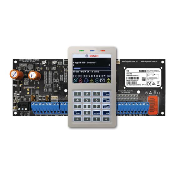
Bosch Solution 6000-IP CC615GWF Manuals
Manuals and User Guides for Bosch Solution 6000-IP CC615GWF. We have 2 Bosch Solution 6000-IP CC615GWF manuals available for free PDF download: Installation Manual, Quick Start Manual

Bosch Solution 6000-IP CC615GWF Installation Manual (164 pages)
Brand: Bosch
|
Category: Security System
|
Size: 8 MB
Table of Contents
-
-
Overview
13 -
Features
13 -
Enclosures
15 -
Keypad Tones
20 -
Zone Wiring
23 -
Lan Overview
25 -
Lan Wiring
25 -
List Options
29 -
Service Mode
30 -
Alpha Text
30 -
Zone Array
31 -
Output Array
31 -
User Pins
40-
Erase User40
-
Add PIN42
-
Delete PIN42
-
View PIN42
-
-
User Tokens
42-
Add Token42
-
Delete Token43
-
Token Status43
-
Edit Token43
-
-
Rf Keyfobs
44-
Add Keyfob44
-
Test Keyfob44
-
-
-
User Name45
-
User Options46
-
Master User46
-
Arm Only46
-
Can Bypass46
-
-
-
-
User46
-
Timezones46
-
PIN Length48
-
Access Route49
-
-
-
-
Area Status51
-
Move to Area52
-
Chime On/Off52
-
Chime Mode53
-
-
-
Area Name53
-
-
-
24Hr Alarm57
-
Auto Arming57
-
-
-
Areas Timers
58-
Exit Time59
-
Entry Time 159
-
Entry Time 259
-
-
Area Testing
61-
Area Watch61
-
Test Options62
-
-
-
Zone Status64
-
Zone Array64
-
Bypass Zones64
-
-
-
Zone Name66
-
-
-
Zone Type66
-
Not Used66
-
-
Pulse Count69
-
-
-
Users70
-
Outputs70
-
Reader70
-
Report Route71
-
-
Report Alarm71
-
Zone Options72
-
Silent Alarm72
-
Sensor Watch73
-
Test on Exit73
-
-
-
Gross Attack74
-
Minor Attack74
-
Zone Options75
-
-
EOL Value75
-
Input Type76
-
-
-
Output Array80
-
Door Status81
-
Door Array81
-
Door Control81
-
Macro Array81
-
-
-
Output Name84
-
Event Type84
-
-
-
-
Pulsing Mode91
-
Macro Group91
-
-
Door Control
92-
Door Name92
-
Door Options92
-
-
Rf Outputs
93 -
-
Strobe Test100
-
Fire Siren Test100
-
-
Comms > Commands101
-
RAS Security PIN102
-
Log Threshold102
-
User RAS PIN102
-
-
TX Format Dest 1103
-
TX Format Dest 2103
-
Test Route103
-
System Route103
-
Emergency Route104
-
Swinger Dialler104
-
-
Myalarm
105-
IP Address105
-
IP Port105
-
Myalarm Options105
-
SIA IP Prefix109
-
Account Number109
-
Account Prefix109
-
Receiver Prefix109
-
-
-
Use SIA Format110
-
SIA with Text110
-
32 Bit Checksum110
-
IP RAS Allowed111
-
UDP User RAS112
-
-
-
Comms Testing
113-
Send Test Report113
-
Test Report Time113
-
Test Route114
-
LAN Scan116
-
LAN Watch116
-
Keypad Volume116
-
Keypad Contrast116
-
Keypad Backlight117
-
-
-
Name117
-
Area Options117
-
All User Areas118
-
Zero Exit Time118
-
Home Area Only119
-
Home Area119
-
General Options119
-
Reader Badging120
-
-
Extinguish121
-
Greetings121
-
Chime Tone121
-
-
Emergency Keys121
-
Door Assignment122
-
Lockout Time123
-
Wi-Fi Settings123
-
SSID Scan123
-
-
-
Timezones
141-
Name141
-
Time141
-
Day142
-
Timezone Options142
-
Invert Logic143
-
-
-
System Holidays
143-
Holiday Name143
-
-
System Options
144-
General Options144
-
Display LAN Fail144
-
Report LAN Fail144
-
Extend LAN Fail144
-
Power up as down145
-
-
-
Report Installer146
-
Allow Defaulting146
-
-
Language147
-
Site Name147
-
-
System Testing
148 -
Section 13
153 -
Specifications
153 -
Section 14
159 -
Index
159
-
Advertisement
Bosch Solution 6000-IP CC615GWF Quick Start Manual (52 pages)
Brand: Bosch
|
Category: Security System
|
Size: 5 MB
Table of Contents
-
-
Features4
-
Overview4
-
LAN Wiring10
-
LAN Overview10
-
PCB Layout12
-
Keypad Tones16
-
Command Menu18
-
Alpha Text18
-
Service Mode19
-
List Options19
-
Zone Array20
-
Door Array20
-
Output Array21
-
Inputs
23-
Commands33
-
Door Array33
-
Door Status33
-
Outputs33
-
Pulsing Mode35
-
Door Name I36
-
Door Options36
-
Scene37
-
Conettix NNC39
-
IP Format39
-
Poll Rate39
-
Receiver IP39
-
Retry Count39
Advertisement