Sign In
Upload
Manuals
Brands
AUMA Manuals
Controller
SARVEx 07.2
AUMA SARVEx 07.2 Manuals
Manuals and User Guides for AUMA SARVEx 07.2. We have
7
AUMA SARVEx 07.2 manuals available for free PDF download: Manual, Operation Instructions Manual, Assembly Instructions
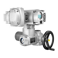
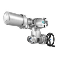
AUMA SARVEx 07.2 Manual (116 pages)
Multi-turn actuators
Brand:
AUMA
| Category:
Industrial Equipment
| Size: 3 MB
Table of Contents
Table of Contents
2
1 Safety Instructions
6
Prerequisites for the Safe Handling of the Product
6
Range of Application
6
Warnings and Notes
7
References and Symbols
7
2 Identification
9
Name Plate
9
Short Description
13
3 Transport, Storage and Packaging
14
Transport
14
Storage
15
Packaging
16
4 Assembly
17
Mounting Position
17
Handwheel Fitting
17
Multi-Turn Actuator: Mount to Valve/Gearbox
17
Output Drive Type a
17
4.3.1.1. Stem Nut: Finish Machining
18
4.3.1.2. Multi-Turn Actuator (with Output Drive Type A): Mount to Valve
19
Output Drive Types B
20
4.3.2.1. Multi-Turn Actuator with Output Drive Types B: Mount to Valve/Gearbox
21
Accessories for Assembly
22
Stem Protection Tube for Rising Valve Stem
22
Mounting Positions of Local Controls
23
Mounting Positions: Modify
24
5 Electrical Connection
25
Basic Information
25
KP/KPH Electrical Connection
28
Terminal Compartment: Open
29
Cable Connection
30
Fieldbus Cables: Connect
32
Terminal Compartment: Close
33
KES Electrical Connection
34
Terminal Compartment: Open
35
Cable Connection
36
Fieldbus Cables: Connect
37
Terminal Compartment: Close
38
KT/KM Electrical Connection
39
Terminal Compartment: Open
40
Cable Connection
41
Fieldbus Cables: Connect
43
Terminal Compartment: Close
44
External Earth Connection
45
Accessories for Electrical Connection
45
Actuator Controls on Wall Bracket
45
Parking Frame
46
Operation
47
Manual Operation
47
Engage Manual Operation
47
Manual Operation: Disengage
47
Motor Operation
48
Local Actuator Operation
48
Actuator Operation from Remote
49
Menu Navigation Via Push Buttons (for Settings and Indications)
49
Menu Layout and Navigation
50
User Level, Password
51
Password Entry
51
Password Change
52
Language in the Display
52
Language Change
53
Indications
54
Indications During Commissioning
54
Indications in the Display
54
Feedback Indications from Actuator and Valve
55
Status Indications According to AUMA Classification
58
Status Indications According to NAMUR Recommendation
58
Indication Lights of Local Controls
60
Optional Indications
61
Mechanical Position Indication Via Indicator Mark
61
Mechanical Position Indication (Self-Adjusting)
61
Signals (Output Signals)
62
Signals Via Fieldbus
62
Status Signals Via Output Contacts (Digital Outputs)
62
Assignment of Outputs
62
Coding the Outputs
62
Analogue Signals (Analogue Outputs)
62
Commissioning (Basic Settings)
64
Positions (of Valve Ports): Define/Check
64
Multiport Valve Function: Activate
64
Actuator Type: Set/Check
64
Gear Reduction Ratio: Set/Check
65
Number of Ports (Positions)
65
Home Port (Zero Position): Set
65
Positions (of Valve Ports): Define/Check
66
Operate to Position Via Push Buttons of the Local Controls
66
Operate to Position from Remote
68
Dead Band
68
Backlash Compensation
68
Signalling Behaviour of Positions: Set/Check
69
Hysteresis for Signalling Intermediate Positions: Set
69
Torque Switching: Set
70
Output Speed (Internal): Set
72
Test Run
73
Direction of Rotation at Mechanical Position Indicator: Check
73
Direction of Rotation at Hollow Shaft/Stem: Check
74
Commissioning (Settings/Options in the Actuator)
76
Switch Compartment: Open/Close
76
Mechanical Position Indicator (Self-Adjusting)
77
Mechanical Position Indicator: Set
77
Gear Stage of the Reduction Gearing: Test/Set
78
Mechanical Position Indication Via Indicator Mark (Not Self-Adjusting)
79
Mechanical Position Indicator: Set
79
Gear Stage of the Reduction Gearing: Test/Set
80
Corrective Action
83
Faults During Commissioning
83
Fault Indications and Warning Indications
83
Signal "Motor Protection Tripped" (Via TMS Device)
87
Fuses
87
Fuses Within the Actuator Controls
87
Motor Protection (Thermal Monitoring)
87
Servicing and Maintenance
88
Preventive Measures for Servicing and Safe Operation
88
Disconnection from the Mains
89
Disconnection from the Mains with KP/KPH and KES Electrical Connection
89
Disconnection from the Mains with KT/KM Electrical Connection
90
Maintenance
91
Disposal and Recycling
91
Technical Data
93
Technical Data Multi-Turn Actuators
93
Technical Data Actuator Controls
95
Spare Parts
102
Multi-Turn Actuators Savex
102
Savex 16.2/Sarvex 07.2
102
Sarvex 16.2 KT/KM
102
Acvexc 01.2 KP/KPH Actuator Controls
104
Acvexc 01.2 KES Actuator Controls
106
Acvexc 01.2 KT/KM Actuator Controls
108
Certificates
110
Declaration of Incorporation and EU Declaration of Conformity
110
Advertisement
AUMA SARVEx 07.2 Operation Instructions Manual (116 pages)
Multi-turn actuators
Brand:
AUMA
| Category:
Controller
| Size: 3 MB
Table of Contents
Table of Contents
2
1 Safety Instructions
5
Prerequisites for the Safe Handling of the Product
5
Range of Application
6
Warnings and Notes
7
References and Symbols
7
2 Short Description
8
3 Name Plate
10
4 Transport, Storage and Packaging
14
Transport
14
Storage
15
5 Assembly
17
Mounting Position
17
Handwheel Fitting
17
Mount Actuator to Valve
17
Overview of Output Drive Types
18
Output Drive Type a
18
5.3.2.1. Multi-Turn Actuator with Output Drive Type A: Mount
19
5.3.2.2. Stem Nut for Output Drive Type A: Finish Machining
21
Output Drive Types B/C/D and E
22
5.3.3.1. Multi-Turn Actuator with Output Drive Type B: Mount
23
Accessories for Assembly
24
Stem Protection Tube for Rising Valve Stem
24
Mounting Positions of Local Controls
25
Mounting Positions: Modify
25
6 Electrical Connection
26
Basic Information
26
Overview of AUMA Electrical Connections
29
KT/KM Electrical Connection
30
Terminal Compartment: Open
31
Cable Connection
32
Fieldbus Cables: Connect
34
6.3.3.1. Fieldbus Connection for Line Topology
34
Terminal Compartment: Close
36
KP/KPH Electrical Connection
37
Terminal Compartment: Open
38
Cable Connection
39
Fieldbus Cables: Connect
40
Terminal Compartment: Close
41
KES Electrical Connection
42
Terminal Compartment: Open
43
Cable Connection
44
Fieldbus Cables: Connect
45
Terminal Compartment: Close
46
External Earth Connection
46
Accessories for Electrical Connection
47
Actuator Controls on Wall Bracket
47
Parking Frame
48
Operation
49
Manual Operation
49
Manual Valve Operation
49
Motor Operation
50
Operating the Actuator from Local Controls
50
Actuator Operation from Remote
51
Menu Navigation Via Push Buttons (for Settings and Indications)
51
Menu Layout and Navigation
52
User Level, Password
53
Password Entry
54
Password Change
54
Timeout for Incorrect Password Entry
55
Language in the Display
55
Language Change
55
Indications
57
Indications During Commissioning
57
Indications in the Display
57
Feedback Signals from Actuator and Valve
58
Status Indications According to AUMA Classification
60
Status Indications According to NAMUR Recommendation
61
Indication Lights of Local Controls
63
Optional Indications
64
Mechanical Position Indication Via Indicator Mark (Not Self-Adjusting)
64
Mechanical Position Indication (Self-Adjusting)
64
Signals (Output Signals)
65
Signals Via Fieldbus
65
Status Signals Via Output Contacts (Digital Outputs)
65
Assignment of Outputs
65
Coding the Outputs
65
Analogue Signals (Analogue Outputs)
66
Commissioning (Basic Settings)
67
Type of Seating: Set
67
Torque Switching: Set
68
Limit Switching: Set
70
Output Speed (Internal): Set
72
Fieldbus Address (Slave Address): Set
73
Test Run
74
Direction of Rotation at Mechanical Position Indicator: Check
74
Direction of Rotation at Hollow Shaft/Stem: Check
76
Limit Switching: Check
76
Commissioning (Settings/Options in the Actuator)
78
Switch Compartment: Open/Close
78
Mechanical Position Indicator (Self-Adjusting)
79
Mechanical Position Indicator: Set
79
Gear Stage of the Reduction Gearing: Test/Set
80
Mechanical Position Indication Via Indicator Mark (Not Self-Adjusting)
81
Mechanical Position Indicator: Set
81
Gear Stage of the Reduction Gearing: Test/Set
82
Corrective Action
85
Faults During Commissioning
85
Fault Indications and Warning Indications
85
Signal for Temperature Warning of PTC Tripping Device
89
Fuses
89
Fuses Within the Actuator Controls
89
Motor Protection (Thermal Monitoring)
89
Servicing and Maintenance
91
Preventive Measures for Servicing and Safe Operation
91
Disconnection from the Mains
92
Disconnection from the Mains with KT/KM Electrical Connection
92
Disconnection from the Mains with KP/KPH and KES Electrical Connection
93
Maintenance
94
Disposal and Recycling
95
Technical Data
96
Technical Data Multi-Turn Actuators
96
Technical Data Actuator Controls
98
Tightening Torques for Screws
103
Spare Parts
104
Multi-Turn Actuators Savex
104
Savex 16.2/Sarvex 07.2
104
Sarvex 16.2 KT/KM
104
Acvexc 01.2 KT/KM Actuator Controls
106
Acvexc 01.2 KP/KPH Actuator Controls
108
Acvexc 01.2 KES Actuator Controls
110
Index
112
AUMA SARVEx 07.2 Operation Instructions Manual (112 pages)
Multi-turn actuators
Brand:
AUMA
| Category:
Controller
| Size: 3 MB
Table of Contents
Table of Contents
2
1 Safety Instructions
5
Basic Information on Safety
5
Range of Application
6
Warnings and Notes
6
References and Symbols
7
2 Identification
8
Name Plate
8
Short Description
11
3 Transport, Storage and Packaging
13
Transport
13
Storage
14
Packaging
15
4 Assembly
16
Mounting Position
16
Handwheel Fitting
16
Multi-Turn Actuator: Mount to Valve/Gearbox
16
Output Drive Type a
16
4.3.1.1. Stem Nut: Finish Machining
17
4.3.1.2. Multi-Turn Actuator (with Output Drive Type A): Mount to Valve
18
Output Drive Types B
19
4.3.2.1. Multi-Turn Actuator with Output Drive Types B: Mount to Valve/Gearbox
20
Accessories for Assembly
21
Stem Protection Tube for Rising Valve Stem
21
Mounting Positions of Local Controls
22
Mounting Positions: Modify
23
5 Electrical Connection
24
Basic Information
24
KP/KPH Electrical Connection
27
Terminal Compartment: Open
28
Cable Connection
29
Fieldbus Cables: Connect
30
Terminal Compartment: Close
31
KES Electrical Connection
32
Terminal Compartment: Open
33
Cable Connection
34
Fieldbus Cables: Connect
35
Terminal Compartment: Close
36
KT/KM Electrical Connection
37
Terminal Compartment: Open
38
Cable Connection
39
Fieldbus Cables: Connect
41
Terminal Compartment: Close
42
External Earth Connection
43
Accessories for Electrical Connection
44
Actuator Controls on Wall Bracket
44
Parking Frame
44
Operation
46
Manual Operation
46
Engage Manual Operation
46
Manual Operation: Disengage
46
Motor Operation
47
Local Actuator Operation
47
Actuator Operation from Remote
48
Menu Navigation Via Push Buttons (for Settings and Indications)
48
Menu Layout and Navigation
49
User Level, Password
50
Password Entry
50
Password Change
51
Language in the Display
51
Language Change
52
Indications
53
Indications During Commissioning
53
Indications in the Display
53
Feedback Indications from Actuator and Valve
54
Status Indications According to AUMA Classification
56
Status Indications According to NAMUR Recommendation
57
Indication Lights of Local Controls
59
Optional Indications
60
Mechanical Position Indication Via Indicator Mark
60
Mechanical Position Indication (Self-Adjusting)
60
Signals (Output Signals)
61
Status Signals Via Output Contacts (Digital Outputs)
61
Assignment of Outputs
61
Coding the Outputs
61
Analogue Signals (Analogue Outputs)
61
Commissioning (Basic Settings)
62
Type of Seating: Set
62
Torque Switching: Set
63
Limit Switching: Set
64
Output Speed (Internal): Set
66
Fieldbus Address (Slave Address), Baud Rate, Parity and Monitoring Time: Set
68
Test Run
68
Direction of Rotation at Mechanical Position Indicator: Check
68
Direction of Rotation at Hollow Shaft/Stem: Check
69
Limit Switching: Check
70
Commissioning (Settings/Options in the Actuator)
71
Switch Compartment: Open/Close
71
Mechanical Position Indicator (Self-Adjusting)
72
Mechanical Position Indicator: Set
72
Gear Stage of the Reduction Gearing: Test/Set
73
Mechanical Position Indication Via Indicator Mark (Not Self-Adjusting)
74
Mechanical Position Indicator: Set
74
Gear Stage of the Reduction Gearing: Test/Set
75
Corrective Action
77
Faults During Operation/Commissioning
77
Fault Indications and Warning Indications
77
Signal "Motor Protection Tripped" (Via TMS Device)
81
Fuses
81
Fuses Within the Actuator Controls
81
Motor Protection (Thermal Monitoring)
81
Servicing and Maintenance
83
Preventive Measures for Servicing and Safe Operation
83
Disconnection from the Mains
84
Disconnection from the Mains with KP/KPH and KES Electrical Connection
84
Disconnection from the Mains with KT/KM Electrical Connection
85
Maintenance
86
Disposal and Recycling
86
Technical Data
88
Technical Data Multi-Turn Actuators
88
Technical Data Actuator Controls
90
Spare Parts
96
Multi-Turn Actuators Savex
96
Savex 16.2/Sarvex 07.2
96
Acvexc 01.2 KP/KPH Actuator Controls
98
Acvexc 01.2 KES Actuator Controls
100
Acvexc 01.2 KT/KM Actuator Controls
102
Certificates
104
Declaration of Incorporation and EU Declaration of Conformity
104
Index
107
Addresses
110
Advertisement
AUMA SARVEx 07.2 Operation Instructions Manual (100 pages)
Multi-turn actuators
Brand:
AUMA
| Category:
Controller
| Size: 2 MB
Table of Contents
Table of Contents
2
1 Safety Instructions
5
Prerequisites for the Safe Handling of the Product
5
Range of Application
6
Warnings and Notes
7
References and Symbols
7
2 Short Description
8
3 Name Plate
10
4 Transport, Lagerung und Verpackung
14
Transport
14
Lagerung
15
Verpackung
16
5 Assembly
17
Mounting Position
17
Handwheel Fitting
17
Mount Actuator to Valve
17
Overview of Output Drive Types
18
Output Drive Type a
18
5.3.2.1. Multi-Turn Actuator with Output Drive Type A: Mount
19
5.3.2.2. Stem Nut for Output Drive Type A: Finish Machining
21
Output Drive Types B/C/D and E
22
5.3.3.1. Multi-Turn Actuator with Output Drive Type B: Mount
23
Accessories for Assembly
24
Stem Protection Tube for Rising Valve Stem
24
Mounting Positions of Local Controls
25
Mounting Positions: Modify
25
6 Electrical Connection
26
Basic Information
26
Overview of AUMA Electrical Connections
28
KT/KM Electrical Connection
29
Terminal Compartment: Open
30
Cable Connection
31
Terminal Compartment: Close
34
KP/KPH Electrical Connection
35
Terminal Compartment: Open
36
Cable Connection
37
Terminal Compartment: Close
38
KES Electrical Connection
39
Terminal Compartment: Open
40
Cable Connection
41
Terminal Compartment: Close
42
External Earth Connection
42
Accessories for Electrical Connection
43
Actuator Controls on Wall Bracket
43
Parking Frame
44
Operation
45
Manual Operation
45
Manual Valve Operation
45
Motor Operation
46
Operating the Actuator from Local Controls
46
Actuator Operation from Remote
47
Menu Navigation Via Push Buttons (for Settings and Indications)
47
Menu Layout and Navigation
48
User Level, Password
49
Password Entry
50
Password Change
50
Timeout for Incorrect Password Entry
51
Language in the Display
51
Language Change
51
Indications
53
Indications During Commissioning
53
Indications on Display
53
Feedback Indications from Actuator and Valve
54
Status Indications According to AUMA Classification
55
Status Indications According to NAMUR Recommendation
56
Indication Lights of Local Controls
58
Signals (Output Signals)
59
Status Signals Via Output Contacts (Digital Outputs)
59
Assignment of Outputs
59
Coding the Outputs
59
Analogue Signals (Analogue Outputs)
59
Commissioning (Basic Settings)
60
Multiport Valve
60
Actuator Type: Set/Check
60
Gear Reduction Ratio: Set/Check
61
Number of Ports (Positions)
61
Home Port (Zero Position): Set
61
Positions (of Valve Ports): Define/Check
62
Operate to Position Via Push Buttons of the Local Controls
63
Operate to Position from Remote
64
Dead Band
65
Correction of Inertia
65
10.1.10. Backlash Compensation
65
10.1.11. Signalling Behaviour of Positions: Set/Check
65
10.1.12. Hysteresis for Signalling Intermediate Positions: Set
66
Torque Switching: Set
66
Output Speed (Internal): Set
68
Test Run
69
Direction of Rotation at Hollow Shaft/Stem: Check
70
Corrective Action
71
Faults During Commissioning
71
Fault Indications and Warning Indications
71
Signal for Temperature Warning of PTC Tripping Device
75
Fuses
75
Fuses Within the Actuator Controls
75
Motor Protection (Thermal Monitoring)
75
Servicing and Maintenance
77
Preventive Measures for Servicing and Safe Operation
77
Disconnection from the Mains
78
Disconnection from the Mains with KT/KM Electrical Connection
78
Disconnection from the Mains with KP/KPH and KES Electrical Connection
79
Maintenance
80
Disposal and Recycling
81
Technical Data
82
Technical Data Multi-Turn Actuators
82
Technical Data Actuator Controls
84
Tightening Torques for Screws
88
Spare Parts
89
Multi-Turn Actuators Savex
89
Savex 16.2/Sarvex
89
Sarvex 16.2 KT/KM
89
Acvexc 01.2 KT/KM Actuator Controls
91
Acvexc 01.2 KP/KPH Actuator Controls
93
Acvexc 01.2 KES Actuator Controls
95
Index
97
AUMA SARVEx 07.2 Operation Instructions Manual (100 pages)
Multi-turn actuators
Brand:
AUMA
| Category:
Controller
| Size: 2 MB
Table of Contents
Table of Contents
2
1 Safety Instructions
5
Prerequisites for the Safe Handling of the Product
5
Range of Application
5
Warnings and Notes
6
References and Symbols
6
2 Identification
8
Name Plate
8
Short Description
12
3 Transport, Storage and Packaging
13
Transport
13
Storage
14
Packaging
15
4 Assembly
16
Mounting Position
16
Valve Attachments
16
Design of Output Drive Type a
16
Design of Output Drive Types B and E
17
Handwheel Fitting
17
Actuator: Mount to Valve
18
Stem Nut for Output Drive Type A: Finish Machining
18
Multi-Turn Actuator with Output Drive Type A: Mount
20
Multi-Turn Actuator with Output Drive Type B: Mount
21
Accessories for Assembly
22
Stem Protection Tube for Rising Valve Stem
22
Mounting Positions of Local Controls
23
Mounting Positions: Modify
24
5 Electrical Connection
25
Basic Information
25
KES Electrical Connection
28
Terminal Compartment: Open
29
Cable Connection
30
Industrial Ethernet Cable: Connect
30
Terminal Compartment: Close
31
External Earth Connection
32
Accessories for Electrical Connection
32
Actuator Controls on Wall Bracket
32
Parking Frame
32
Operation
34
Manual Operation
34
Manual Valve Operation
34
Motor Operation
35
Operating the Actuator from Local Controls
35
Actuator Operation from Remote
36
Menu Navigation Via Push Buttons (for Settings and Indications)
36
Menu Layout and Navigation
37
User Level, Password
38
Password Entry
39
Password Change
39
Language in the Display
40
Language Change
40
Indications
42
Indications During Commissioning
42
Indications in the Display
42
Feedback Signals from Actuator and Valve
43
Status Indications According to AUMA Classification
45
Status Indications According to NAMUR Recommendation
46
Indication Lights of Local Controls
48
Optional Indications
49
Mechanical Position Indication Via Indicator Mark (Not Self-Adjusting)
49
Mechanical Position Indication (Self-Adjusting)
49
Signals (Output Signals)
50
Status Signals Via Output Contacts (Digital Outputs)
50
Coding the Outputs
50
Analogue Signals (Analogue Outputs)
50
Commissioning (Basic Settings)
51
Type of Seating: Set
51
Torque Switching: Set
52
Limit Switching: Set
54
Output Speed (Internal): Set
56
Connection between Ethernet/Ip Module and Computer: Check
57
Ethernet/Ip Module Configuration
58
Test Run
59
Direction of Rotation at Mechanical Position Indicator: Check
59
Direction of Rotation at Hollow Shaft/Stem: Check
61
Limit Switching: Check
61
Commissioning (Settings/Options in the Actuator)
63
Switch Compartment: Open/Close
63
Mechanical Position Indicator (Self-Adjusting)
64
Mechanical Position Indicator: Set
64
Gear Stage of the Reduction Gearing: Test/Set
65
Mechanical Position Indication Via Indicator Mark (Not Self-Adjusting)
66
Mechanical Position Indicator: Set
66
Gear Stage of the Reduction Gearing: Test/Set
67
Corrective Action
70
Faults During Commissioning
70
Fault Indications and Warning Indications
70
Signal for Temperature Warning of PTC Tripping Device
74
Fuses
74
Fuses Within the Actuator Controls
74
Fuse Replacement
74
Replace Fuses
74
Test/Replace Fuses
75
Motor Protection (Thermal Monitoring)
75
Servicing and Maintenance
77
Preventive Measures for Servicing and Safe Operation
77
Disconnection from the Mains
78
Disconnection from the Mains with KP/KPH and KES Electrical Connection
78
Maintenance
79
Disposal and Recycling
79
Technical Data
81
Technical Data Multi-Turn Actuators
81
Technical Data Actuator Controls
83
Spare Parts
88
Multi-Turn Actuators SA(V)Ex
88
Sa(V)Ex 16.2 / SAR(V)Ex 07.2
88
Sar(V)Ex 16.2 KES
88
Acvexc 01.2 Actuator Controls with KES Electrical Connection
90
Certificates
92
Declaration of Incorporation and EU Declaration of Conformity
92
Index
95
Addresses
98
AUMA SARVEx 07.2 Manual (24 pages)
Multi-turn actuators with actuator controls SFC version
Brand:
AUMA
| Category:
Controller
| Size: 1 MB
Table of Contents
Table of Contents
3
Safety-Related Figures
15
Determination of the Safety-Related Figures
15
SIL Declaration of Conformity (Example)
16
Index
21
Addresses
22
AUMA SARVEx 07.2 Assembly Instructions (3 pages)
Square head for pit application
Brand:
AUMA
| Category:
Controller
| Size: 0 MB
Advertisement
Related Products
AUMA SARExC 07.1
AUMA SGExC 07.1-F07
AUMA SGExC 07.1-F10
AUMA SARVEx 07.6
AUMA SAVE 07.2/ADY 23 Series
AUMA SAVE 07.6/ADY 24 Series
AUMA SAEx 07.2-UW
AUMA SAEx 07.6-UW
AUMA ACVExC 01.2 Series
AUMA SGExC 05.1-F05
AUMA Categories
Controller
Industrial Equipment
Control Unit
Control Systems
Outboard Motor
More AUMA Manuals
Login
Sign In
OR
Sign in with Facebook
Sign in with Google
Upload manual
Upload from disk
Upload from URL