AUMA SAVEx 07.2 Manual
Multi-turn actuators
Hide thumbs
Also See for SAVEx 07.2:
- Operation instructions manual (116 pages) ,
- Manual (24 pages) ,
- Assembly instructions (3 pages)
Table of Contents
Advertisement
Quick Links
Multi-turn actuators
SAVEx 07.2
SAVEx16.2
SARVEx 07.2
SARVEx16.2
Control unit: electronic (MWG)
with actuator controls
ACVExC 01.2 Non-Intrusive
Multiport valve version
Control
Parallel
Profibus DP
Profinet
Modbus RTU
Modbus TCP/IP
Foundation Fieldbus
HART
Operation instructions
Montage, Bedienung, Inbetriebnahme
Advertisement
Table of Contents

Related Manuals for AUMA SAVEx 07.2


Summary of Contents for AUMA SAVEx 07.2
- Page 1 Multi-turn actuators SAVEx 07.2 SAVEx16.2 SARVEx 07.2 SARVEx16.2 Control unit: electronic (MWG) with actuator controls ACVExC 01.2 Non-Intrusive Multiport valve version Control Parallel Profibus DP Profinet Modbus RTU Modbus TCP/IP Foundation Fieldbus HART Operation instructions Montage, Bedienung, Inbetriebnahme...
-
Page 2: Table Of Contents
Manual (Operation and setting ) of actuator controls ACVExC 01.2 Foundation Fieldbus Manual (Fieldbus device integration) of actuator controls ACVExC 01.2 Foundation Fieldbus Reference documents can be downloaded from the Internet (www.auma.com) or ordered directly from AUMA (refer to <Addresses>). - Page 3 7.1. Indications during commissioning 7.2. Indications in the display 7.2.1. Feedback indications from actuator and valve 7.2.2. Status indications according to AUMA classification 7.2.3. Status indications according to NAMUR recommendation 7.3. Indication lights of local controls 7.4. Optional indications 7.4.1.
- Page 4 Disposal and recycling Technical data......................... 13.1. Technical data Multi-turn actuators 13.2. Technical data Actuator controls Spare parts..........................14.1. Multi-turn actuators SAVEx 07.2 SAVEx 16.2/SARVEx 07.2 SARVEx 16.2 KT/KM 14.2. ACVExC 01.2 KP/KPH actuator controls 14.3. ACVExC 01.2 KES actuator controls 14.4.
- Page 5 SAVEx 07.2 SAVEx16.2 / SARVEx 07.2 SARVEx16.2 Control unit: electronic (MWG) ACVExC 01.2 Non-Intrusive Foundation Fieldbus Table of contents Index............................Addresses..........................
-
Page 6: Safety Instructions
To ensure safe device operation, the maintenance instructions included in this manual Maintenance must be observed. Any device modification requires prior written consent of the manufacturer. 1.2. Range of application AUMA multi-turn actuators are designed for the operation of industrial valves, e.g. globe valves, gate valves, butterfly valves, and ball valves. -
Page 7: Warnings And Notes
1 and 2. If temperatures >40 °C are to be expected at the valve mounting flange or the valve stem (e.g. due to hot media), please consult AUMA. Temperatures > 40 °C are not considered with regards to the non-electrical explosion protection. - Page 8 SAVEx 07.2 SAVEx16.2 / SARVEx 07.2 SARVEx16.2 Control unit: electronic (MWG) Safety instructions ACVExC 01.2 Non-Intrusive Foundation Fieldbus Symbol for CLOSED (valve closed) Symbol for OPEN (valve open) Via the menu to parameter Describes the menu path to the parameter. When using the push buttons of local controls, the required parameter can be quickly found on the display.
-
Page 9: Identification
SAVEx 07.2 SAVEx16.2 / SARVEx 07.2 SARVEx16.2 Control unit: electronic (MWG) ACVExC 01.2 Non-Intrusive Foundation Fieldbus Identification Identification 2.1. Name plate Figure 1: Arrangement of name plates Actuator name plate Actuator controls name plate Motor name plate Additional plate, e.g. KKS plate (Power Plant Classification System) - Page 10 SAVEx 07.2 SAVEx16.2 / SARVEx 07.2 SARVEx16.2 Control unit: electronic (MWG) Identification ACVExC 01.2 Non-Intrusive Foundation Fieldbus Actuator controls name plate Figure 3: Name plate for actuator controls (example) (= manufacturer logo) Type designation Order number Serial number Actuator terminal plan...
- Page 11 SAVEx 07.2 SAVEx16.2 / SARVEx 07.2 SARVEx16.2 Control unit: electronic (MWG) ACVExC 01.2 Non-Intrusive Foundation Fieldbus Identification Approval plate in explosion-proof version Ex symbol, CE mark, number of test authority Ex certificate (number) Classification: Not used Non-electrical explosion protection Threads for line bushings at electrical connection...
- Page 12 Control via Foundation Fieldbus interface and control voltage for OPEN-CLOSE control via digital inputs (OPEN, STOP, CLOSE) When registered as authorised user, you may use our AUMA Assistant App to scan Data Matrix code the Data Matrix code and directly access the order-related product documents without having to enter order number or serial number.
-
Page 13: Short Description
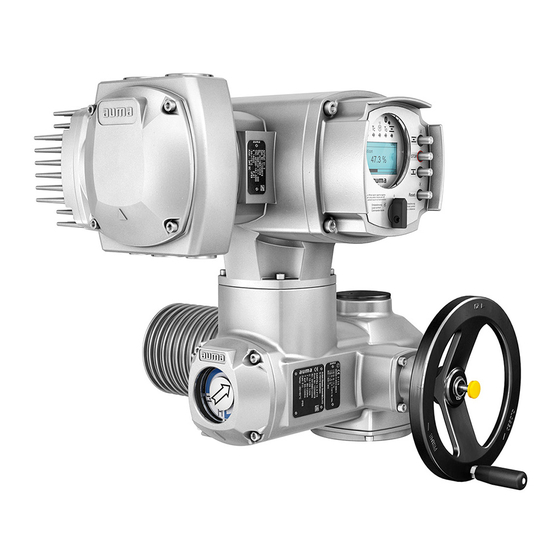
A multi-turn actuator is an actuator which transmits torque to a valve for at least one full revolution. It is capable of withstanding thrust. AUMA multi-turn actuators are driven by an electric motor and are capable of withstanding thrust in combination with output drive type A. For manual operation, a handwheel is provided. -
Page 14: Transport, Storage And Packaging
SAVEx 07.2 SAVEx16.2 / SARVEx 07.2 SARVEx16.2 Control unit: electronic (MWG) Transport, storage and packaging ACVExC 01.2 Non-Intrusive Foundation Fieldbus Transport, storage and packaging 3.1. Transport For transport to place of installation, use sturdy packaging. Hovering load! Death or serious injury. -
Page 15: Storage
ADY... SARVEx 16.2 Refer to motor name plate Indicated weight includes AUMA NORM multi-turn actuator with 3-phase AC motor, electrical con- nection in standard version, output drive type B1 and handwheel. For other output drive types, heed additional weights. Table 5: Weights for output drive type A 07.2... -
Page 16: Packaging
SAVEx 07.2 SAVEx16.2 / SARVEx 07.2 SARVEx16.2 Control unit: electronic (MWG) Transport, storage and packaging ACVExC 01.2 Non-Intrusive Foundation Fieldbus Prior to storage: Protect uncoated surfaces, in particular the output drive parts and mounting surface, with long-term corrosion protection agent. -
Page 17: Assembly
SAVEx 07.2 SAVEx16.2 / SARVEx 07.2 SARVEx16.2 Control unit: electronic (MWG) ACVExC 01.2 Non-Intrusive Foundation Fieldbus Assembly Assembly 4.1. Mounting position The product described in this document can be operated in any mounting position. Restriction: When using oil instead of grease within the actuator gear housing, the hollow shaft mounting position must be perpendicular, with the flange pointing downward. -
Page 18: 4.3.1.1. Stem Nut: Finish Machining
SAVEx 07.2 SAVEx16.2 / SARVEx 07.2 SARVEx16.2 Control unit: electronic (MWG) Assembly ACVExC 01.2 Non-Intrusive Foundation Fieldbus Output mounting flange [1] with axial bearing stem nut [2] form one unit. Torque is Design transmitted to valve stem [3] via stem nut [2]. -
Page 19: 4.3.1.2. Multi-Turn Actuator (With Output Drive Type A): Mount To Valve
SAVEx 07.2 SAVEx16.2 / SARVEx 07.2 SARVEx16.2 Control unit: electronic (MWG) ACVExC 01.2 Non-Intrusive Foundation Fieldbus Assembly Remove axial bearing washers [2.1] and axial needle roller and cage assemblies [2.2] from stem nut [1]. Drill and bore stem nut [1] and cut thread. -
Page 20: Output Drive Types B
SAVEx 07.2 SAVEx16.2 / SARVEx 07.2 SARVEx16.2 Control unit: electronic (MWG) Assembly ACVExC 01.2 Non-Intrusive Foundation Fieldbus 10. Fasten screws [3] crosswise with a torque according to table. Table 7: Tightening torques for screws Threads Tightening torque [Nm] Strength class A2-80/A4 80 11. -
Page 21: 4.3.2.1. Multi-Turn Actuator With Output Drive Types B: Mount To Valve/Gearbox
SAVEx 07.2 SAVEx16.2 / SARVEx 07.2 SARVEx16.2 Control unit: electronic (MWG) ACVExC 01.2 Non-Intrusive Foundation Fieldbus Assembly Figure 12: Output drive type B Flange multi-turn actuator (e.g. F07) Hollow shaft Output drive sleeve (illustration examples) [3] B/B1/B2 and [3]* B3/B4/E, respectively with bore and keyway Gearbox/valve shaft with parallel key Spigot at valve flanges should be loose fit. -
Page 22: Accessories For Assembly
SAVEx 07.2 SAVEx16.2 / SARVEx 07.2 SARVEx16.2 Control unit: electronic (MWG) Assembly ACVExC 01.2 Non-Intrusive Foundation Fieldbus Fasten multi-turn actuator with screws according to table. Information: We recommend applying liquid thread sealing material to the screws to avoid contact corrosion. -
Page 23: Mounting Positions Of Local Controls
SAVEx 07.2 SAVEx16.2 / SARVEx 07.2 SARVEx16.2 Control unit: electronic (MWG) ACVExC 01.2 Non-Intrusive Foundation Fieldbus Assembly Screw stem protection tube [2] into thread and tighten it firmly. Information: For stem protection tubes made of two or more segments, all parts have to be thoroughly screwed together. -
Page 24: Mounting Positions: Modify
SAVEx 07.2 SAVEx16.2 / SARVEx 07.2 SARVEx16.2 Control unit: electronic (MWG) Assembly ACVExC 01.2 Non-Intrusive Foundation Fieldbus 4.5.1. Mounting positions: modify Flameproof enclosure, danger of explosion! Risk of death or serious injury. Before opening, ensure that there is no explosive gas and no voltage. -
Page 25: Electrical Connection
It can plan also be requested from AUMA (state order number, refer to name plate) or downloaded directly from the Internet (http://www.auma.com). Actuator controls (actuators) are suitable for use in TN and TT networks with directly Permissible networks earthed star point for mains voltage up to maximum 480 V AC. - Page 26 SAVEx 07.2 SAVEx16.2 / SARVEx 07.2 SARVEx16.2 Control unit: electronic (MWG) Electrical connection ACVExC 01.2 Non-Intrusive Foundation Fieldbus Table 9: Protection on site Multi-turn 3-phase AC motor 380 V 480 V/50 Hz 60 Hz Fuse actuator Consumed rated Blow characteristics:...
- Page 27 SAVEx 07.2 SAVEx16.2 / SARVEx 07.2 SARVEx16.2 Control unit: electronic (MWG) ACVExC 01.2 Non-Intrusive Foundation Fieldbus Electrical connection All input signals (control inputs) must be supplied with the same potential. Potential of customer connections All output signals (status signals) must be supplied with the same potential.
-
Page 28: Kp/Kph Electrical Connection
SAVEx 07.2 SAVEx16.2 / SARVEx 07.2 SARVEx16.2 Control unit: electronic (MWG) Electrical connection ACVExC 01.2 Non-Intrusive Foundation Fieldbus Fieldbus cable Type A Type B Type C Type D (Reference) Wave attenuation 3 dB/km 5 dB/km 8 dB/km 8 dB/km at 39 kHz... -
Page 29: Terminal Compartment: Open
SAVEx 07.2 SAVEx16.2 / SARVEx 07.2 SARVEx16.2 Control unit: electronic (MWG) ACVExC 01.2 Non-Intrusive Foundation Fieldbus Electrical connection The terminal compartment (with screw-type terminals) is designed in protection type Ex e (increased safety). Plug-in connection is made via the frame. Removing the cover is sufficient for connecting the cables. -
Page 30: Cable Connection
SAVEx 07.2 SAVEx16.2 / SARVEx 07.2 SARVEx16.2 Control unit: electronic (MWG) Electrical connection ACVExC 01.2 Non-Intrusive Foundation Fieldbus Insert cable glands suitable for connecting cables. Information: When selecting cable glands observe type of protection (with Ex e approval) and enclosure protection IP (refer to name plate). - Page 31 SAVEx 07.2 SAVEx16.2 / SARVEx 07.2 SARVEx16.2 Control unit: electronic (MWG) ACVExC 01.2 Non-Intrusive Foundation Fieldbus Electrical connection In case of a fault: Hazardous voltage while protective earth conductor is NOT connected! Risk of electric shock. Connect all protective earth conductors.
-
Page 32: Fieldbus Cables: Connect
SARVEx16.2 Control unit: electronic (MWG) Electrical connection ACVExC 01.2 Non-Intrusive Foundation Fieldbus 5.2.3. Fieldbus cables: connect Figure 23: Terminal assignment for line topology (1-channel or 2-channel for AUMA redundancy I) □ Channel 1: Further fieldbus devices will follow (standard) ▣... -
Page 33: Terminal Compartment: Close
SAVEx 07.2 SAVEx16.2 / SARVEx 07.2 SARVEx16.2 Control unit: electronic (MWG) ACVExC 01.2 Non-Intrusive Foundation Fieldbus Electrical connection 5.2.4. Terminal compartment: close Figure 24: Close terminal compartment Cover (figure shows KP version) Screws for cover O-ring Blanking plugs Cable gland Flameproof frame Clean sealing faces of cover [1] and frame [6]. -
Page 34: Kes Electrical Connection
SAVEx 07.2 SAVEx16.2 / SARVEx 07.2 SARVEx16.2 Control unit: electronic (MWG) Electrical connection ACVExC 01.2 Non-Intrusive Foundation Fieldbus 5.3. KES electrical connection Figure 25: KES electrical connection Terminal blocks Connection frame Short description KES plug-in electrical connection with terminal blocks for power and control contacts. -
Page 35: Terminal Compartment: Open
SAVEx 07.2 SAVEx16.2 / SARVEx 07.2 SARVEx16.2 Control unit: electronic (MWG) ACVExC 01.2 Non-Intrusive Foundation Fieldbus Electrical connection 5.3.1. Terminal compartment: open Figure 26: Open terminal compartment Cover (illustration shows type of protection Ex e) Screws for cover O-ring Blanking plugs... -
Page 36: Cable Connection
SAVEx 07.2 SAVEx16.2 / SARVEx 07.2 SARVEx16.2 Control unit: electronic (MWG) Electrical connection ACVExC 01.2 Non-Intrusive Foundation Fieldbus 5.3.2. Cable connection Table 15: Terminal cross sections and terminal tightening torques Designation Terminal cross sections Tightening torques Power contacts (U, V, W) max. -
Page 37: Fieldbus Cables: Connect
SARVEx16.2 Control unit: electronic (MWG) ACVExC 01.2 Non-Intrusive Foundation Fieldbus Electrical connection 5.3.3. Fieldbus cables: connect Figure 29: Terminal assignment for line topology (1-channel or 2-channel for AUMA redundancy I) □ Channel 1: Further fieldbus devices will follow (standard) ▣... -
Page 38: Terminal Compartment: Close
SAVEx 07.2 SAVEx16.2 / SARVEx 07.2 SARVEx16.2 Control unit: electronic (MWG) Electrical connection ACVExC 01.2 Non-Intrusive Foundation Fieldbus 5.3.4. Terminal compartment: close Figure 30: Close terminal compartment Cover (illustration shows type of protection Ex e) Screws for cover O-ring Blanking plugs... -
Page 39: Kt/Km Electrical Connection
SAVEx 07.2 SAVEx16.2 / SARVEx 07.2 SARVEx16.2 Control unit: electronic (MWG) ACVExC 01.2 Non-Intrusive Foundation Fieldbus Electrical connection 5.4. KT/KM electrical connection Figure 31: KT/KM electrical connection Terminal carrier with screw-type/spring clamp terminals Connection frame Figure shows KT version KT plug-in electrical connection with screw-type terminals for power connection and Short description spring clamp terminals for control contacts. -
Page 40: Terminal Compartment: Open
SAVEx 07.2 SAVEx16.2 / SARVEx 07.2 SARVEx16.2 Control unit: electronic (MWG) Electrical connection ACVExC 01.2 Non-Intrusive Foundation Fieldbus 5.4.1. Terminal compartment: open Figure 32: Open terminal compartment Cover (illustration shows KT version in type of protection Ex e) Screws for cover... -
Page 41: Cable Connection
SAVEx 07.2 SAVEx16.2 / SARVEx 07.2 SARVEx16.2 Control unit: electronic (MWG) ACVExC 01.2 Non-Intrusive Foundation Fieldbus Electrical connection 5.4.2. Cable connection Table 17: Terminal cross sections and tightening torques Designation Terminal cross sections Connection type Power contacts Flexible or solid:... - Page 42 SAVEx 07.2 SAVEx16.2 / SARVEx 07.2 SARVEx16.2 Control unit: electronic (MWG) Electrical connection ACVExC 01.2 Non-Intrusive Foundation Fieldbus In case of a fault: Hazardous voltage while protective earth conductor is NOT connected! Risk of electric shock. Connect all protective earth conductors.
-
Page 43: Fieldbus Cables: Connect
SARVEx16.2 Control unit: electronic (MWG) ACVExC 01.2 Non-Intrusive Foundation Fieldbus Electrical connection 5.4.3. Fieldbus cables: connect Figure 36: Terminal assignment for line topology (1-channel or 2-channel for AUMA redundancy I) □ Channel 1: Further fieldbus devices will follow (standard) ▣... -
Page 44: Terminal Compartment: Close
SAVEx 07.2 SAVEx16.2 / SARVEx 07.2 SARVEx16.2 Control unit: electronic (MWG) Electrical connection ACVExC 01.2 Non-Intrusive Foundation Fieldbus 5.4.4. Terminal compartment: close Figure 37: Close terminal compartment Cover (illustration shows KT version in type of protection Ex e) Screws for cover... -
Page 45: External Earth Connection
SAVEx 07.2 SAVEx16.2 / SARVEx 07.2 SARVEx16.2 Control unit: electronic (MWG) ACVExC 01.2 Non-Intrusive Foundation Fieldbus Electrical connection 5.5. External earth connection Figure 38: Earth connection for multi-turn actuator External earth connection (U-bracket) for connection to equipotential compensation. Application Table 18:... -
Page 46: Parking Frame
Permissible length of connecting cables: max. 16 m. Observe prior to connec- Longer cables require an external filter (available on request) tion We recommend using an AUMA “LSW” cable set. 5.6.2. Parking frame Figure 40: Parking frame, example with Ex plug/socket connector and cover Parking frame for safe storage of a disconnected plug or cover. -
Page 47: Operation
SAVEx 07.2 SAVEx16.2 / SARVEx 07.2 SARVEx16.2 Control unit: electronic (MWG) ACVExC 01.2 Non-Intrusive Foundation Fieldbus Operation Operation 6.1. Manual operation For purposes of setting and commissioning, in case of motor or power failure, the actuator may be operated manually. Manual operation is engaged by an internal change-over mechanism. -
Page 48: Motor Operation
SAVEx 07.2 SAVEx16.2 / SARVEx 07.2 SARVEx16.2 Control unit: electronic (MWG) Operation ACVExC 01.2 Non-Intrusive Foundation Fieldbus 6.2. Motor operation Perform all commissioning settings and the test run prior to motor operation. Valve damage due to incorrect basic setting! Prior to electrical operation of the actuator, the basic settings i.e. type of seating, torque and limit switching have to be completed. -
Page 49: Actuator Operation From Remote
SAVEx 07.2 SAVEx16.2 / SARVEx 07.2 SARVEx16.2 Control unit: electronic (MWG) ACVExC 01.2 Non-Intrusive Foundation Fieldbus Operation 6.2.2. Actuator operation from remote Risk of immediate actuator operation when switching on! Risk of personal injuries or damage to the valve If the actuator starts unexpectedly: Immediately turn selector switch to position 0 (OFF). -
Page 50: Menu Layout And Navigation
SAVEx 07.2 SAVEx16.2 / SARVEx 07.2 SARVEx16.2 Control unit: electronic (MWG) Operation ACVExC 01.2 Non-Intrusive Foundation Fieldbus Table 19: Important push button functions for menu navigation Push buttons Navigation sup- Functions port on display Up ▲ Change screen/selection Change values Enter figures from 0 to 9 Down ▼... -
Page 51: User Level, Password
SAVEx 07.2 SAVEx16.2 / SARVEx 07.2 SARVEx16.2 Control unit: electronic (MWG) ACVExC 01.2 Non-Intrusive Foundation Fieldbus Operation the push buttons on the local controls have not been operated within 10 minutes or by briefly pressing C When entering the ID within the main menu, screens can be displayed directly (without Direct display via ID clicking through). -
Page 52: Password Change
SAVEx 07.2 SAVEx16.2 / SARVEx 07.2 SARVEx16.2 Control unit: electronic (MWG) Operation ACVExC 01.2 Non-Intrusive Foundation Fieldbus Select higher user level via Up ▲ and confirm with Display indicates: Password 0*** Use push buttons Up ▲ Down ▼ to select figures 0 to 9. -
Page 53: Language Change
SAVEx 07.2 SAVEx16.2 / SARVEx 07.2 SARVEx16.2 Control unit: electronic (MWG) ACVExC 01.2 Non-Intrusive Foundation Fieldbus Operation 6.5.1. Language change Display... M0009 Language M0049 Set selector switch to position 0 (OFF). Select main menu Press push button C Setup and hold it down for approx. 3 seconds. -
Page 54: Indications
SAVEx 07.2 SAVEx16.2 / SARVEx 07.2 SARVEx16.2 Control unit: electronic (MWG) Indications ACVExC 01.2 Non-Intrusive Foundation Fieldbus Indications 7.1. Indications during commissioning When switching on the power supply, all LEDs on the local controls illuminate for LED test approx. 1 second. This optical feedback indicates that the voltage supply is connected to the controls and all LEDs are operable. -
Page 55: Feedback Indications From Actuator And Valve
SAVEx 07.2 SAVEx16.2 / SARVEx 07.2 SARVEx16.2 Control unit: electronic (MWG) ACVExC 01.2 Non-Intrusive Foundation Fieldbus Indications Figure 54: Information in the status bar (top) Operation mode Error symbol (only for faults and warnings) ID number: S = Status page... - Page 56 SAVEx 07.2 SAVEx16.2 / SARVEx 07.2 SARVEx16.2 Control unit: electronic (MWG) Indications ACVExC 01.2 Non-Intrusive Foundation Fieldbus Figure 58: Torque allows to select the unit displayed (percent %, Newton metre Nm Select unit The push button or "foot-pound" ft-lb Figure 59: Units of torque 100 % indication equals the max.
- Page 57 SAVEx 07.2 SAVEx16.2 / SARVEx 07.2 SARVEx16.2 Control unit: electronic (MWG) ACVExC 01.2 Non-Intrusive Foundation Fieldbus Indications Figure 61: Indication for setpoint control (positioner) Position setpoint Actual position value The pivot points and their operation behaviour (operation profile) are shown on the Pivot point axis pivot point axis by means of symbols.
-
Page 58: Status Indications According To Auma Classification
SARVEx16.2 Control unit: electronic (MWG) Indications ACVExC 01.2 Non-Intrusive Foundation Fieldbus 7.2.2. Status indications according to AUMA classification These indications are available if the parameter Diagnostic classific. M0539 is set to AUMA. Warnings (S0005) If a warning has occurred, the display shows S0005: the number of warnings occurred a blinking question mark after approx. - Page 59 SAVEx 07.2 SAVEx16.2 / SARVEx 07.2 SARVEx16.2 Control unit: electronic (MWG) ACVExC 01.2 Non-Intrusive Foundation Fieldbus Indications the number of indications occurred a blinking triangle with question mark after approx. 3 seconds Figure 67: Out of specification For further information, please also refer to <Corrective action>.
-
Page 60: Indication Lights Of Local Controls
SAVEx 07.2 SAVEx16.2 / SARVEx 07.2 SARVEx16.2 Control unit: electronic (MWG) Indications ACVExC 01.2 Non-Intrusive Foundation Fieldbus Figure 70: Failure For further information, please also refer to <Corrective action>. 7.3. Indication lights of local controls Figure 71: Arrangement and signification of indication lights... -
Page 61: Optional Indications
SAVEx 07.2 SAVEx16.2 / SARVEx 07.2 SARVEx16.2 Control unit: electronic (MWG) ACVExC 01.2 Non-Intrusive Foundation Fieldbus Indications 7.4. Optional indications 7.4.1. Mechanical position indication via indicator mark Figure 72: Mechanical position indicator End position OPEN reached End position CLOSED reached... -
Page 62: Signals (Output Signals)
Feedback signals via fieldbus can be configured. The configuration is only defined via the transducer blocks of the discrete input function blocks. The DD (Device Description) can be downloaded at www.auma.com. Information For information on the feedback signals via fieldbus and the configuration of the parameters via fieldbus interface, refer to Manual (Device integration fieldbus) Foundation Fieldbus. - Page 63 SAVEx 07.2 SAVEx16.2 / SARVEx 07.2 SARVEx16.2 Control unit: electronic (MWG) ACVExC 01.2 Non-Intrusive Foundation Fieldbus Signals (output signals) Signal: E2 = 0/4 20 mA (galvanically isolated) Valve position Designation in the wiring diagram: AOUT1 (position) Torque feedback Signal: E6 = 0/4...
-
Page 64: Commissioning (Basic Settings)
SAVEx 07.2 SAVEx16.2 / SARVEx 07.2 SARVEx16.2 Control unit: electronic (MWG) Commissioning (basic settings) ACVExC 01.2 Non-Intrusive Foundation Fieldbus Commissioning (basic settings) Set selector switch to position 0 (OFF). Information: The selector switch is not a mains switch. When positioned to 0 (OFF), the actuator cannot be operated. -
Page 65: Gear Reduction Ratio: Set/Check
Multiport valve M1140 Actuator type M1142 Default value: Actuator type set in the factory Setting ranges: Selection list of all AUMA actuators 9.1.3. Gear reduction ratio: set/check The reduction ratio of the gear stage of the actuator mounted to the valve gearbox must be set here. -
Page 66: Positions (Of Valve Ports): Define/Check
SAVEx 07.2 SAVEx16.2 / SARVEx 07.2 SARVEx16.2 Control unit: electronic (MWG) Commissioning (basic settings) ACVExC 01.2 Non-Intrusive Foundation Fieldbus In a next step, confirm this position (with Yes) as home port via parameter MPV home port M1162. As an alternative, the home port position can also be confirmed via a signal at a digital input. - Page 67 SAVEx 07.2 SAVEx16.2 / SARVEx 07.2 SARVEx16.2 Control unit: electronic (MWG) ACVExC 01.2 Non-Intrusive Foundation Fieldbus Commissioning (basic settings) Figure 74: Status indication of multiport valve (selector switch in position OFF) Operation in clockwise or counterclockwise direction: When changing the selector switch to position Local control (LOCAL), the display...
-
Page 68: Operate To Position From Remote
SAVEx 07.2 SAVEx16.2 / SARVEx 07.2 SARVEx16.2 Control unit: electronic (MWG) Commissioning (basic settings) ACVExC 01.2 Non-Intrusive Foundation Fieldbus 9.1.8. Operate to position from Remote For direct operation to position from remote, make sure that selector switch position Remote control (REMOTE) is selected. -
Page 69: Signalling Behaviour Of Positions: Set/Check
SAVEx 07.2 SAVEx16.2 / SARVEx 07.2 SARVEx16.2 Control unit: electronic (MWG) ACVExC 01.2 Non-Intrusive Foundation Fieldbus Commissioning (basic settings) Multiport valve M1140 Backlash comp. M1146 Default value: 0.00° Setting range: 0.00 – 36.0° (degrees) 9.1.11. Signalling behaviour of positions: set/check... -
Page 70: Torque Switching: Set
Figure 79: Switching behaviour for signalling behaviours B, C, D and hysteresis 3.0°. Switch-on point ( ● ) Switch-off point (○) Pulse duration = 2 times XT + hysteresis Required user level: AUMA (6). Customer settings M0041 Multiport valve M1140 Hysteresis M1148 Default values: 0.5°... - Page 71 SAVEx 07.2 SAVEx16.2 / SARVEx 07.2 SARVEx16.2 Control unit: electronic (MWG) ACVExC 01.2 Non-Intrusive Foundation Fieldbus Commissioning (basic settings) Select parameter either: Select parameter click via the menu to parameter, or via direct display: press and enter ID M0088. Display indicates: Trip torque CLOSE CLOSE or OPEN Up ▲...
-
Page 72: Output Speed (Internal): Set
SAVEx 07.2 SAVEx16.2 / SARVEx 07.2 SARVEx16.2 Control unit: electronic (MWG) Commissioning (basic settings) ACVExC 01.2 Non-Intrusive Foundation Fieldbus or, in case the torque applied is lower than the preset tripping torque: in selector switch position Local control (LOCAL) via push button RESET. -
Page 73: Test Run
SAVEx 07.2 SAVEx16.2 / SARVEx 07.2 SARVEx16.2 Control unit: electronic (MWG) ACVExC 01.2 Non-Intrusive Foundation Fieldbus Commissioning (basic settings) Press Edit. Display indicates: Specialist (4) → continue with step 7 in bottom row Up ▲ Down ▼ Esc → continue with step 11 Log on user Up ▲... -
Page 74: Direction Of Rotation At Hollow Shaft/Stem: Check
SAVEx 07.2 SAVEx16.2 / SARVEx 07.2 SARVEx16.2 Control unit: electronic (MWG) Commissioning (basic settings) ACVExC 01.2 Non-Intrusive Foundation Fieldbus Switch on actuator in direction CLOSE and observe the direction of rotation on the mechanical position indication: For self-adjusting mechanical position indication:... - Page 75 SAVEx 07.2 SAVEx16.2 / SARVEx 07.2 SARVEx16.2 Control unit: electronic (MWG) ACVExC 01.2 Non-Intrusive Foundation Fieldbus Commissioning (basic settings) Switch on actuator in direction CLOSE and observe direction of rotation at hollow shaft [3] or stem [5]: The direction of rotation is correct if the actuator moves in direction CLOSE and the hollow shaft in clockwise direction, or the stem moves downward.
-
Page 76: Commissioning (Settings/Options In The Actuator)
SAVEx 07.2 SAVEx16.2 / SARVEx 07.2 SARVEx16.2 Control unit: electronic (MWG) Commissioning (settings/options in the actuator) ACVExC 01.2 Non-Intrusive Foundation Fieldbus Commissioning (settings/options in the actuator) For actuators without mechanical position indicator (cover without indicator glass), no settings are required within the actuator when commissioning. -
Page 77: Mechanical Position Indicator (Self-Adjusting)
SAVEx 07.2 SAVEx16.2 / SARVEx 07.2 SARVEx16.2 Control unit: electronic (MWG) ACVExC 01.2 Non-Intrusive Foundation Fieldbus Commissioning (settings/options in the actuator) Flameproof enclosure, danger of explosion! Risk of death or serious injury. Before opening, ensure that there is no explosive gas and no voltage. -
Page 78: Gear Stage Of The Reduction Gearing: Test/Set
SAVEx 07.2 SAVEx16.2 / SARVEx 07.2 SARVEx16.2 Control unit: electronic (MWG) Commissioning (settings/options in the actuator) ACVExC 01.2 Non-Intrusive Foundation Fieldbus Push both lower discs with the symbols (OPEN) and (CLOSED) towards each other. The disc with the arrow is thereby... -
Page 79: Mechanical Position Indication Via Indicator Mark (Not Self-Adjusting)
SAVEx 07.2 SAVEx16.2 / SARVEx 07.2 SARVEx16.2 Control unit: electronic (MWG) ACVExC 01.2 Non-Intrusive Foundation Fieldbus Commissioning (settings/options in the actuator) Refer to table and check if turns/stroke correspond to the setting of the reduction gearing (stages 1 9). Table 23:... -
Page 80: Gear Stage Of The Reduction Gearing: Test/Set
SAVEx 07.2 SAVEx16.2 / SARVEx 07.2 SARVEx16.2 Control unit: electronic (MWG) Commissioning (settings/options in the actuator) ACVExC 01.2 Non-Intrusive Foundation Fieldbus Turn lower indicator disc until symbol (CLOSED) is in alignment with the mark on the cover. Move actuator to end position OPEN. - Page 81 SAVEx 07.2 SAVEx16.2 / SARVEx 07.2 SARVEx16.2 Control unit: electronic (MWG) ACVExC 01.2 Non-Intrusive Foundation Fieldbus Commissioning (settings/options in the actuator) Refer to table and check if turns/stroke of the actuator correspond to the setting of the reduction gearing (stages 1 9).
- Page 82 SAVEx 07.2 SAVEx16.2 / SARVEx 07.2 SARVEx16.2 Control unit: electronic (MWG) Commissioning (settings/options in the actuator) ACVExC 01.2 Non-Intrusive Foundation Fieldbus Figure 91: Control unit with reduction gearing Screw Crown wheel...
-
Page 83: Corrective Action
SAVEx 07.2 SAVEx16.2 / SARVEx 07.2 SARVEx16.2 Control unit: electronic (MWG) ACVExC 01.2 Non-Intrusive Foundation Fieldbus Corrective action Corrective action 11.1. Faults during commissioning Table 26: Faults during operation/commissioning Fault Description/cause Remedy Mechanical position indicator cannot Reduction gearing is not suitable for turns/stroke Set gear stage of the reduction gearing. - Page 84 SAVEx 07.2 SAVEx16.2 / SARVEx 07.2 SARVEx16.2 Control unit: electronic (MWG) Corrective action ACVExC 01.2 Non-Intrusive Foundation Fieldbus Faults and warnings via status indications in the display Indication on display Description/cause Remedy S0009 Collective signal 08: For indicated value > 0: Press push button Indication according to NAMUR recommendation tails.
- Page 85 SAVEx 07.2 SAVEx16.2 / SARVEx 07.2 SARVEx16.2 Control unit: electronic (MWG) ACVExC 01.2 Non-Intrusive Foundation Fieldbus Corrective action Warnings and Out of specification Indication on display Description/cause Remedy Wrn no reaction No actuator reaction to operation commands within Check movement at actuator.
- Page 86 Selector switch is not in position REMOTE. Set selector switch to position REMOTE. Service active Operation via service interface (Bluetooth) and Exit service software. AUMA CDT service software. Disabled Actuator is in operation mode Disabled. Check setting and status of function <Local controls enable>.
-
Page 87: Signal "Motor Protection Tripped" (Via Tms Device)
SAVEx 07.2 SAVEx16.2 / SARVEx 07.2 SARVEx16.2 Control unit: electronic (MWG) ACVExC 01.2 Non-Intrusive Foundation Fieldbus Corrective action 11.2.1. Signal "Motor protection tripped” (via TMS device) The “Motor protection tripped” signal (wiring diagram designation: TMS-M ) must be monitored: “Motor protection tripped” = contact NC open (contact NO = closed) -
Page 88: Servicing And Maintenance
Therefore, we recommend contacting our service. Only perform servicing and maintenance tasks when the device is switched off. AUMA AUMA offers extensive service such as servicing and maintenance as well as Service & Support customer product training. For the relevant contact addresses, please refer to <Addresses>... -
Page 89: Disconnection From The Mains
Loosen the screws [2]. Remove electrical connection. Cover [1] and plug-in type frame [4] or connection frame [5] remain together. Seal open plug/socket connection, e.g. using AUMA protection cover and parking frame. Clean sealing faces of plug/socket connector and housing. -
Page 90: Disconnection From The Mains With Kt/Km Electrical Connection
SAVEx 07.2 SAVEx16.2 / SARVEx 07.2 SARVEx16.2 Control unit: electronic (MWG) Servicing and maintenance ACVExC 01.2 Non-Intrusive Foundation Fieldbus Apply a thin film of non-acidic grease (e.g. petroleum jelly) to the O-ring and insert it correctly. Replace electrical connection and fasten screws evenly crosswise. -
Page 91: Maintenance
Electrical connection cables must be placed properly and in perfect condition. Thoroughly touch up any possible damage to painting to prevent corrosion. Original paint in small quantities can be supplied by AUMA . Cable entries, cable glands, plugs etc. have to be checked for correct tightness and sealing. - Page 92 SAVEx 07.2 SAVEx16.2 / SARVEx 07.2 SARVEx16.2 Control unit: electronic (MWG) Servicing and maintenance ACVExC 01.2 Non-Intrusive Foundation Fieldbus greases and oils The following generally applies: Greases and oils are hazardous to water and must not be released into the environment.
-
Page 93: Technical Data
Indication whether manual operation is active/not active via single switch (1 change-over contact) tion) Electrical connection Standard: AUMA Ex plug/socket connector with screw-type terminals (KP) Option: Ex plug/socket connector with terminal blocks (KES), increased safety Ex e Ex plug/socket connector with terminal blocks (KES), flameproof enclosure Ex d... - Page 94 Two-component iron-mica combination Colour Standard: AUMA silver-grey (similar to RAL 7037) Option: Available colours on request Lifetime AUMA multi-turn actuators meet or exceed the lifetime requirements of EN 15714-2. Detailed information can be provided on request. Noise level < 72 dB (A)
-
Page 95: Technical Data Actuator Controls
SAVEx 07.2 SAVEx16.2 / SARVEx 07.2 SARVEx16.2 Control unit: electronic (MWG) ACVExC 01.2 Non-Intrusive Foundation Fieldbus Technical data 13.2. Technical data Actuator controls Features and functions Explosion protection Refer to name plate Certificates and standards Certificates are attached to the device. All standards applied and their respective issues are indicated on these certificates. - Page 96 Bluetooth class II chip, version 2.1: With a range up to 10 m in industrial environments, supports the SPP Bluetooth profile (Serial Port Profile). Communication interface Required accessories: AUMA CDT (Commissioning and Diagnostic Tool for Windows-based PC) AUMA Assistant App (Commissioning and Diagnostic Tool for Android devices)
- Page 97 SAVEx 07.2 SAVEx16.2 / SARVEx 07.2 SARVEx16.2 Control unit: electronic (MWG) ACVExC 01.2 Non-Intrusive Foundation Fieldbus Technical data Features and functions Application functions Standard: Selectable type of seating, limit or torque seating for end position OPEN and end po- sition CLOSED...
- Page 98 Electrical connection Standard: AUMA Ex plug/socket connector with screw-type terminals (KP) Options: AUMA Ex plug/socket connector with terminal blocks (KES) AUMA Ex plug/socket connector (KT); screw-type motor terminals; push-in type control terminals Threads for cable entries Standard: Metric threads Options:...
- Page 99 SAVEx 07.2 SAVEx16.2 / SARVEx 07.2 SARVEx16.2 Control unit: electronic (MWG) ACVExC 01.2 Non-Intrusive Foundation Fieldbus Technical data Function blocks of Foundation Fieldbus interface Function blocks of the output signals 8 Discrete Output (DO) function blocks for discrete output signals, e.g.:...
- Page 100 IP68 EN 60529 Terminal compartment additionally sealed against interior (double sealed) According to AUMA definition, enclosure protection IP68 meets the following requirements: Depth of water: maximum 8 m head of water Duration of continuous immersion in water: Max. 96 hours Up to 10 operations during continuous immersion Modulating duty is not possible during continuous immersion.
- Page 101 SAVEx16.2 / SARVEx 07.2 SARVEx16.2 Control unit: electronic (MWG) ACVExC 01.2 Non-Intrusive Foundation Fieldbus Technical data Further information Weight Approx. 7 kg (with AUMA plug/socket connector) Directives ATEX Directive: (2014/34/EU) Electromagnetic Compatibility (EMC): (2014/30/EU) Low Voltage Directive: (2014/35/EU) Machinery Directive: (2006/42/EC)
-
Page 102: Spare Parts
SAVEx 07.2 SAVEx16.2 / SARVEx 07.2 SARVEx16.2 Control unit: electronic (MWG) Spare parts ACVExC 01.2 Non-Intrusive Foundation Fieldbus Spare parts 14.1. Multi-turn actuators SAVEx 07.2 SAVEx 16.2/SARVEx 07.2 SARVEx 16.2 KT/KM... - Page 103 Spare parts Please state device type and our order number (see name plate) when ordering spare parts. Only original AUMA spare parts should be used. Failure to use original spare parts voids the warranty and exempts AUMA from any liability. Representation of spare parts may slightly vary from actual delivery.
-
Page 104: Acvexc 01.2 Kp/Kph Actuator Controls
SAVEx 07.2 SAVEx16.2 / SARVEx 07.2 SARVEx16.2 Control unit: electronic (MWG) Spare parts ACVExC 01.2 Non-Intrusive Foundation Fieldbus 14.2. ACVExC 01.2 KP/KPH actuator controls... - Page 105 Spare parts Please state device type and our order number (see name plate) when ordering spare parts. Only original AUMA spare parts should be used. Failure to use original spare parts voids the warranty and exempts AUMA from any liability. Representation of spare parts may slightly vary from actual delivery.
-
Page 106: Acvexc 01.2 Kes Actuator Controls
SAVEx 07.2 SAVEx16.2 / SARVEx 07.2 SARVEx16.2 Control unit: electronic (MWG) Spare parts ACVExC 01.2 Non-Intrusive Foundation Fieldbus 14.3. ACVExC 01.2 KES actuator controls... - Page 107 Spare parts Please state device type and our order number (see name plate) when ordering spare parts. Only original AUMA spare parts should be used. Failure to use original spare parts voids the warranty and exempts AUMA from any liability. Representation of spare parts may slightly vary from actual delivery.
-
Page 108: Acvexc 01.2 Kt/Km Actuator Controls
SAVEx 07.2 SAVEx16.2 / SARVEx 07.2 SARVEx16.2 Control unit: electronic (MWG) Spare parts ACVExC 01.2 Non-Intrusive Foundation Fieldbus 14.4. ACVExC 01.2 KT/KM actuator controls... - Page 109 Spare parts Please state device type and our order number (see name plate) when ordering spare parts. Only original AUMA spare parts should be used. Failure to use original spare parts voids the warranty and exempts AUMA from any liability. Representation of spare parts may slightly vary from actual delivery.
-
Page 110: Certificates
Certificates are valid as from the indicated date of issue. Subject to changes without Information notice. The latest versions are attached to the device upon delivery and also available for download at http://www.auma.com. 15.1. Declaration of Incorporation and EU Declaration of Conformity... - Page 111 SAVEx 07.2 SAVEx16.2 / SARVEx 07.2 SARVEx16.2 Control unit: electronic (MWG) ACVExC 01.2 Non-Intrusive Foundation Fieldbus Index Index Earth connection Electrical connection 25, 93 Accessories (electrical con- Enclosure protection 9, 10, 94, 100 nection) Error - indication on display Accessories for assembly...
- Page 112 SAVEx 07.2 SAVEx16.2 / SARVEx 07.2 SARVEx16.2 Control unit: electronic (MWG) Index ACVExC 01.2 Non-Intrusive Foundation Fieldbus Language in the display Packaging LEDs (indication lights) Parking frame Lifetime Password Line topology 32, 37, 43 Password change Local actuator operation Password entry...
- Page 113 SAVEx 07.2 SAVEx16.2 / SARVEx 07.2 SARVEx16.2 Control unit: electronic (MWG) ACVExC 01.2 Non-Intrusive Foundation Fieldbus Index Safety instructions Wall bracket Safety instructions/warnings Warnings - indication on dis- Safety measures play Safety standards Wiring diagram 12, 25 Self-locking Self-retaining Year of production...
- Page 114 Europe AUMA Finland Oy AUMA-LUSA Representative Office, Lda. FI 02230 Espoo PT 2730-033 Barcarena Tel +358 9 5840 22 Tel +351 211 307 100 AUMA Riester GmbH & Co. KG auma@auma.fi geral@aumalusa.pt www.auma.fi Location Muellheim SAUTECH DE 79373 Muellheim AUMA France S.A.R.L.
- Page 115 AUMA worldwide America AUMA Actuators (China) Co., Ltd. FLOWTORK TECHNOLOGIES CN 215499 Taicang CORPORATION AUMA Argentina Rep.Office Tel +86 512 3302 6900 PH 1550 Mandaluyong City AR Buenos Aires mailbox@auma-china.com Tel +63 2 532 4058 Tel +54 11 4737 9026 www.auma-china.com...
- Page 116 AUMA Riester GmbH & Co. KG P.O. Box 1362 DE 79373 Muellheim Tel +49 7631 809 - 0 Fax +49 7631 809 - 1250 info@auma.com www.auma.com Y008.901/003/en/1.19 For detailed information on AUMA products, refer to the Internet: www.auma.com...
Need help?
Do you have a question about the SAVEx 07.2 and is the answer not in the manual?
Questions and answers