Sign In
Upload
Manuals
Brands
Aristocrat Manuals
Video Game
USA MAV500/MKVI
Aristocrat USA MAV500/MKVI Manuals
Manuals and User Guides for Aristocrat USA MAV500/MKVI. We have
1
Aristocrat USA MAV500/MKVI manual available for free PDF download: Service Manual
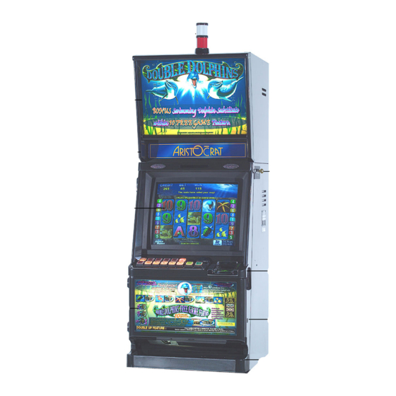
Aristocrat USA MAV500/MKVI Service Manual (364 pages)
Aristocrat Technologies Video Gaming Machine Service manual
Brand:
Aristocrat
| Category:
Video Game
| Size: 10.27 MB
Table of Contents
_____Chapter 1_____
6
Physical Description
6
Table of Contents
6
Specifications
6
Physical Description
8
Table 1-1 Video Gaming Machine Modules
9
Table 1-2 Machine Keys
13
Basic Operation
14
Play Mode
14
Operator Mode
15
Figure 1-3 Basic Game Operation in Play Mode
16
Specifications
17
Table 1-3 Physical Characteristics
17
Table 1-4 Power Requirements
17
Table 1-5 Environment
17
Table 1-6 Compliances
18
________Chapter 2________
20
Pre-Installation Requirements
21
Inspection on Delivery
25
Installation Procedure
25
Mounting
25
Pre-Start Connections, Checks and Power up
26
Commissioning the Machine
28
________Chapter 3________
30
Machine Modes
31
Modes of Operation
31
Play Mode
31
Player Operation
33
Video Display
35
Sounds and Tunes
35
Light Tower
36
Pushbuttons
37
Machine Self-Monitoring
38
Electronic Meters
40
Operator Mode
41
Machine Identification
41
Accounting Information
43
Diagnostic Information Menu
43
Test/Diagnostics Menu
43
Operator Setup/Selections
43
Miscellaneous Menu
43
Current Lockup Menu Items
105
________Chapter 4________
108
General Description
110
Technical Description
113
Cabinet
113
Key Switches
113
Cash Box and Chute
114
Logic Cage
115
PMM Panel
116
Sound System
117
Door
117
Cabinet Security
117
Cabinet (Main) Door
118
Door Latch
118
Door Fluorescent Lighting and Artwork
119
MID Trim Panel
121
Playbuttons
121
Monitor Mask
124
Coin Tray
124
Top Box
125
Top Box Door
127
Artwork
127
Fluorescent Lighting
127
Light Tower
128
General Maintenance
130
________Chapter 5________
132
Physical Description
134
Basic Operation
136
Functional Specification
137
Input Capability
137
Output Requirements
138
Mains GPO
138
Monitor Output
138
Generic Output 24 V DC
138
Fluoro Output 24 V DC
138
Output 12 V DC
138
Overcurrent Protection
139
Overvoltage Protection
139
Inrush Current
139
Control Signals
139
Low-Power Mode Signal
139
Power Fail Signal
139
Physical Connections
140
External Mains Switch Outputs
140
Off-Line Converter Output
140
Fluorescent Lamp Outputs
142
Removal and Replacement Procedures
142
Fuses
142
Power Supply Assembly
142
General Maintenance
143
________Chapter 6________
144
Overview
146
Coin Comparator
147
Basic Operation
147
Functional Description
148
Replacing the Sample Coin
151
Removal and Replacement
152
Comparator Connector Pinouts
152
Fault Finding
153
Condor Plus Coin Validator CP133S
154
Basic Operation
154
Removal and Replacement
156
Cleaning Procedure
157
CP133S Coin Validator Connector Pinouts
161
Fault Finding
162
Diverter Solenoid and Photo-Optic Sensor
163
Physical Description
163
Basic Operation
163
General Maintenance
164
________Chapter 7________
166
Physical Description
168
Basic Operation
171
Functional Description
172
Fault Finding
174
Removal and Replacement Procedures
175
Disassembly and Assembly Procedures
176
General Maintenance
177
Test Procedure
177
_______Chapter 8_______
179
Vfm4 Non-Isolated Serial Interface
190
Clearance of Embedded Bill Acceptor Stacker
195
Removing Bill Acceptor Stacker
195
Periodic Maintenance
196
Troubleshooting
197
Removal and Replacement Procedures
205
Removing WBA Cash Box
205
Removing WBA Transport
205
Bill Acceptor Jams
205
Care and Maintenance
206
Cleaning
206
Calibration
207
Troubleshooting the WBA
208
Power Supply
212
Cable Connector
213
On-Screen-Display Controls (Osd)
214
Procedure Guidelines
214
Pushbutton Control Panel
214
Adjustment Processes
215
Adjustments for Main Functional Group
215
Additional Maintenance
216
Colour Adjustment
216
Language Function
216
Recall Function (Factory Settings)
216
Touchscreen Option
218
Touchscreen Operation
218
Machine Interface
219
Touchscreen Specifications
221
Notes on Handling
221
________Chapter 10________
224
Introduction
226
Physical Description
226
Diagrams and Component Locations
227
Functional Description
228
Technical Description
230
Microprocessor
232
Video
235
Audio
235
Communication Port
236
Reset
236
External I/O Expansion
236
Memory
237
Battery Backup Circuit
238
Real Time Clock
239
Security
239
Machine Peripherals
240
SPI Bus Driver and Multiplexer Circuitry
242
Serial Channels
243
Communication Configuration Board
243
Interface with the Power Control System
244
Mikohn Link Progressive Interface
245
In-Circuit Emulator (Not Fitted)
245
FPGA JTAG Interface (Not Fitted)
245
Mechanical Switches
245
Backplane Board
246
Removal and Replacement Procedures
246
Description of Connectors
247
Fan Connector - J1
248
Communications Configuration Board - J3
248
PCI Mezzanine Connectors - J5 and J6
250
Smart Card - J7
251
Memory Expansion Board - J9 and J12
252
Security and I/O Expansion Connector - P21
259
______Chapter 11______
263
Physical Description
265
Circuit Diagrams and Component Locations
265
Functional Description
267
Address Decoding
267
Mikohn Interface
271
Pushbuttons
272
Communication
272
BACC Denomination Lamps
272
DIP Switch Banks
273
Interrupt Request
273
Hard Meters and Lamps
273
Expansion I/O
274
Door Security
274
Power
274
Removal and Replacement Procedures
275
________Chapter 12________
282
Physical Description
284
Diagrams and Component Locations
284
System Overview
286
Bill Acceptor
286
Electrical Connections
287
Main Board/Backplane Din, Jp20/P
288
Main Board/Backplane Din, Jp22/P
290
Main Board/Backplane Din, Jp21/P
292
Extended I/O Driver Board
295
I/O Driver Board 64-Way DIN41612 Connector, J1
295
I/O Driver Board 64-Way DIN41612 Connector, J2
296
I/O Driver Board 96-Way DIN41612 Connector, J3
298
Backplane Peripheral Connectors
300
Debug, P1
300
Light Tower / Meters / BACC Security, P2
300
Logic Door, P3
300
Monitor, P4
301
Speakers, P5
301
Low Resolution Video, P6
302
Hopper / Printer, P7
302
Com6 and Com7 Spare Serial Outputs, P8
303
Battery Backed Security Switches, P9
303
Bill Acceptor (Bacc) Lights, P
304
Pushbuttons & Pushbutton Lamps, P
304
Spare I/O, P12
305
Keyswitches & Bacc, P
305
Door Distribution, P14
306
Spare Power, P15
306
________Chapter 13________
310
Physical Description
312
Circuit Diagrams and Component Locations
312
Functional Description
314
Removal and Replacement Procedures
320
13.4 Connector Pin Assignments
323
General Maintenance
323
______Chapter 14______
325
14.1 Physical Description
328
Circuit Diagrams and Component Locations
328
Functional Description
329
Connector Pin Assignments
330
Connection from Backplane Board
330
Connection to Light Tower Lamps
331
General Maintenance
331
Removal and Replacement Procedures
331
______Chapter 15______
333
Block Diagram of Amplifier Module
335
Functional Description
335
Amplifier Power Required
336
Audio SPL Requirement of EGM
336
Interface Requirements
336
Power Interface
336
Spare Power Interface
337
Optional AC Power Interface
337
Stereo Audio Input Interface
338
Audio Level Adjustment Input Interface
338
Audio High Frequency Left and Right Output Interfaces
339
Audio Low Frequency Left and Right and Bridge Mono Output Interface
340
Other Specifications
342
Physical
342
Mounting Arrangements
343
Removal and Replacement
343
Technical Description
353
Functional Description
356
Removal and Replacement Procedures
359
Paper Roll Replacement
359
Ribbon Cassette Replacement
362
Connector Pin Assignments
363
General Maintenance
363
Advertisement
Advertisement
Related Products
Aristocrat Categories
Video Game
More Aristocrat Manuals
Login
Sign In
OR
Sign in with Facebook
Sign in with Google
Upload manual
Upload from disk
Upload from URL